Table of Contents
Advertisement
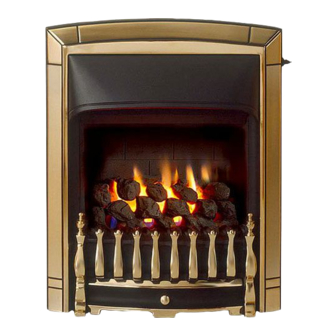
INSTALLER AND OWNER GUIDE
Model 953
INSET LIVE FUEL EFFECT GAS FIRE
INCORPORATING THE
VALOR FIRES
Fitted with one of the following fascia.
Alpha, Decadent, Dream,
Elegant, Eternal, Masquerade,
Excelsior
(GC No. 32-032-72)
We trust that this guide gives
sufficient details to enable this
appliance to be installed, operated
and maintained satisfactorily.
However, if further information is
required, our
Valor Technical Helpline will be
pleased to help.
Telephone 0844 879 35 88 (National
call rates apply in the United
Kingdom).
In the Republic of Ireland
Telephone 01 842 8222.
INSTALLER: Please leave this guide with owner
©
GDC Group Ltd. 2013
CONTROL
Obsession
or
5122724/08
Advertisement
Chapters
Table of Contents

Related Manuals for Valor 953


Summary of Contents for Valor 953
- Page 1 However, if further information is required, our Valor Technical Helpline will be pleased to help. Telephone 0844 879 35 88 (National call rates apply in the United Kingdom).
- Page 2 Warning: Any person who does any unauthorised act in relation to a copyright work may be liable to criminal prosecution and civil claims for damages. Valor Fires, GDC Group Ltd, Millbrook House, Grange Drive, Hedge End, Southampton, S030 2DF. www.valor.co.uk...
- Page 3 BS EN ISO 9001 quality system accepted by the British Standards Institute. The Highest Standards Valor Fires is a member of SBGI and HHIC (Heating and Hot water Industry Council) that work to ensure high standards of safety, quality and performance. Careful Installation...
-
Page 4: Installer Guide
INSTALLER GUIDE INSTALLER GUIDE FOR OWNER GUIDE SEE PAGES 42 TO 55 Page 4 © GDC Group Ltd. 2013... -
Page 5: Table Of Contents
INSTALLER GUIDE CONTENTS Section Heading Page INSTALLER GUIDE 4 - 41 OWNER GUIDE 42 - 55 1. SAFETY AND UNPACKING 2. APPLIANCE DATA AND EFFICIENCY 3. GENERAL INSTALLATION REQUIREMENTS 3.1 Regulations, Standards and Law. 3.2 Ventilation requirements. 3.3 The Atmosphere sensing device (ASD). 3.4 Fireguard requirements. -
Page 6: Installer Guide
INSTALLER GUIDE CONTENTS (Continued) Section Heading Page 10. BURNER INSTALLATION 10.1 Burner and supply pipe installation. 10.2 Preliminary burner checks. 10.2.1 Lighting the burner. 10.2.2 Operating the burner. 10.3 Inlet pressure check. 10.4 Fitting the burner tray trim. 11. FITTING THE FASCIA 12. -
Page 7: Safety And Unpacking
INSTALLER GUIDE 1. SAFETY AND UNPACKING Installer Before continuing any further with the installation of this appliance please read the following guide to manual handling. The approximate lifting weight (kg) of this appliance is as below: Model Heat Engine Firefront Combined Weight Alpha 2.10... -
Page 8: Appliance Data And Efficiency
Model Efficiency % (Gross) 953 when converted to LPG. The gross calorific value of the fuel has been used for this efficiency calculation. The test data from which it has been calculated has been certified by Advantica Certification services (0087). -
Page 9: General Installation Requirements
INSTALLER GUIDE Conversion factor from net to gross efficiency Natural Gas 0.901 0.921 3. GENERAL INSTALLATION REQUIREMENTS 3.1 Regulations, Standards and Law. The installation must be in accordance with these instructions. For the user’s protection, in the United Kingdom it is the law that all gas appliances are installed by competent persons in accordance with the current edition of the Gas Safety (Installation and Use) Regulations. -
Page 10: Ventilation Requirements
INSTALLER GUIDE 3.2 Ventilation requirements. Normal adventitious ventilation is usually sufficient to satisfy the ventilation requirements of this appliance. In GB reference should be made to BS 5871 Part 2 and in IE reference should be made to the current edition of IS 813 “Domestic Gas Installations”... -
Page 11: Fireplace Preparation
INSTALLER GUIDE 3.7 Fireplace preparation. 3.7.1 If the fireplace opening is an underfloor draught type, it must be sealed to stop any draughts. 3.7.2 The fireplace floor should be reasonably flat to ensure that the convection box can be installed without it rocking and so that a good seal can be made at the bottom front of the box. -
Page 12: Fireplace Clearances
INSTALLER GUIDE 3.9 Fireplace clearances. 3.9.1 The minimum height from the base of the fireplace opening to the underside of any shelf made from wood or other combustible materials is detailed below. • For a shelf up to 150mm deep: Minimum height = 750mm. •... - Page 13 INSTALLER GUIDE Dimension Alpha Elegant Dream/Masq./Excel. Eternal Decadent Obsession 492mm 492mm 518mm 514mm 529mm 530mm 598mm 598mm 636mm 611mm 630mm 621mm 84mm 84mm 94mm 76mm 120mm 96mm Figure 3. Appliance dimensions (Fascia may differ from that shown and is subject to manufacturing tolerances).
-
Page 14: Installation Options
INSTALLER GUIDE 3.10 Installation options. In the United Kingdom, as supplied, the appliance can be installed in the following situations: - 3.10.1 Conventional fireplace and hearth. To a fireplace complete with hearth as shown in figure 4. Chair brick removal may not be required providing at least 50mm clearance is... -
Page 15: Metal Flue Box And Hearth
INSTALLER GUIDE 3.10.2 Metal flue box and hearth. The appliance can be installed to a fireplace incorporating a metal flue box complying with the constructional requirements of the current edition of BS 715 and with a flue conforming to BS EN 1856 part 1. The dimensions of the flue box must conform to those shown in figure 5. -
Page 16: Precast Concrete Or Clay Flue Block System And Hearth
INSTALLER GUIDE 3.10.3 Precast concrete or clay flue block system and hearth. The appliance can be installed to a precast concrete or clay flue block system conforming to BS1289 or BS EN 1858 with dimensions as in figure 6. BS 1289 part 1 recommends there should be an air space or insulation between the flue blocks and the plaster because heat transfer may cause cracking on directly plastered flues. -
Page 17: Flues
INSTALLER GUIDE 3.11 Flues. 1. Suitable flues and minimum flue sizes are as follows: It should be noted that, as with many appliances, sharp bends or horizontal runs in metal flues at the top of the system can be a cause of problems in these types of installation. -
Page 18: Pack Contents
INSTALLER GUIDE 4. PACK CONTENTS The items required for this appliance are packed in sections. Section 1 - Fire unit contains: 1 Convection box and burner assembly 1 Loose parts pack including: - 1 Grommet for rear of convection box 1 Strip of floor sealing tape 1 Flue restrictor 4 Fibre plugs... - Page 19 INSTALLER GUIDE Figure 7. Pack contents Dream, Masquerade and Excelsior Figure 7. Pack contents continued (Firefront shown here may vary as per model) Page 19 © GDC Group Ltd. 2013...
- Page 20 INSTALLER GUIDE Figure 7. Pack contents continued Page 20 © GDC Group Ltd. 2013...
-
Page 21: Fireplace Check
INSTALLER GUIDE 5. FIREPLACE CHECK 5.1 Soundness for appliance attachment. Two primary methods of retaining the appliance are provided: - By fixing to the fireplace front surround. Using concealed fire retaining cables fixed to the rear of the fireplace opening together with secondary fixing to the fireplace floor. -
Page 22: Ignition Check
INSTALLER GUIDE 6. IGNITION CHECK Before attempting to install, it is worth checking that the electronic ignition system performs satisfactorily. Fit the battery to the ignition block located below the burner tray at the left side (See figure 8). The +ve and -ve terminal positions are marked on the battery holder body. -
Page 23: Preparing Appliance For Installation
INSTALLER GUIDE 8. PREPARING APPLIANCE FOR INSTALLATION 8.1 Appliance preparation. 1. Remove any transit tape and packing and inspect for any evidence of mishandling which might affect the performance. Each unit is flame tested before it leaves the factory and as a result there may be slight discolouration around the burner ports. -
Page 24: The Flue Restrictor
INSTALLER GUIDE 8.3 The flue restrictor. This appliance is supplied with a flue restrictor for use where the flue draught is excessive. Generally we recommend the restrictor is NOT fitted where a precast flue, metal flue box or a flue liner is used, however, certain flues may work sufficiently to warrant its use. -
Page 25: Method 2 - Cable Retention
INSTALLER GUIDE 9.2 Method 2 - Cable retention. 1. Make sure that the relevant areas at the fireplace back are sound enough to take the eyebolts. If these areas have deteriorated due to prolonged use they should be made sound with suitable cement. -
Page 26: Floor Sealing
INSTALLER GUIDE 6. Thread the cables through the eyebolts in the rear wall. Return the cables through the holes near the bottom corners of the convection box back panel (See figure 16). 7. Place the convection box fully back into the fireplace opening so that it is sealed against the fireplace front surround. -
Page 27: Burner Installation
INSTALLER GUIDE 10. BURNER INSTALLATION 10.1 Burner and supply pipe installation. 1. Refit the burner unit to the convection box with two screws. 2. Connect the supply line to the appliance. 3. Pressure check the installation pipework for gas soundness. In the United Kingdom check in accordance with the current edition of BS6891. -
Page 28: Inlet Pressure Check
INSTALLER GUIDE 10.3 Inlet pressure check. The appliance is pre-set to give the correct heat input at the inlet pressure shown in section 2 of this manual. No adjustment is necessary. 1. Check the inlet pressure by fitting a pressure gauge at the test point. -
Page 29: Fitting The Ceramic Fuel Effect
INSTALLER GUIDE 2. Swing the bottom control linking bar towards the centre of the fire to clear the right side of the fascia. Slide the fascia sideways, if necessary, to align the bottom fixing holes with those in the convection box (This will not be possible on the Dream). -
Page 30: Firefront Casting Installation
INSTALLER GUIDE 13. FIREFRONT CASTING INSTALLATION 13.1 Fitting the Alpha, Eternal, Elegant and Obsession firefront casting. 1. Fit the fire front casting to the fascia. Locate the two screw heads at the rear top corners of the casting through the keyhole slots at the inner sides of the fascia. If the screw heads do not project enough or project too far, the screws can be adjusted. -
Page 31: Full Operating Checks
INSTALLER GUIDE 14. FULL OPERATING CHECKS Open the isolating valve on the inlet ‘T’ connector. 14.1 Recheck the control settings. The control position markings on the fascia are shown in figure 28. Please note: When first turned on from cold, the flames will appear predominantly blue. -
Page 32: Spillage And Flame Supervision Checks
INSTALLER GUIDE 15. SPILLAGE AND FLAME SUPERVISION CHECKS 15.1 Check for spillage. A spillage check must be made before leaving the installed appliance with the customer. Make this with all the ceramic fuel effect pieces, fascia and firefront in position. 1. - Page 33 INSTALLER GUIDE out. Listen for a snap sound at the gas tap. Note the time when the sound is heard. This sound is caused by an electromagnetic valve shutting off the gas supply through the tap. The valve is located in the body of the tap. The valve should operate within 60 seconds of the pilot going out.
-
Page 34: Final Review
INSTALLER GUIDE 16. FINAL REVIEW 1. COMPLETE THE INFORMATION IN THE WARRANTY AND SERVICE SECTION OF THE OWNER GUIDE (See last pages of the OWNER guide). 2. Visually inspect the appliance. Clean off any marks incurred during installation. 3. Advise the customer how to operate the fire. 4. -
Page 35: Servicing & Parts Replacement
INSTALLER GUIDE 17. SERVICING & PARTS REPLACEMENT Always turn off the gas supply and allow to cool completely before commencing any servicing (The appliance inlet “T” connector incorporates an isolating valve). It is recommended that, at least once a year, the appliance is disconnected and the fireplace opening checked and cleared of any debris. -
Page 36: Checking The Aeration Setting Of The Burner
INSTALLER GUIDE 17.1 Checking the aeration setting of the burner. 1. The aeration shutter is factory set and should not require adjustment. If the shutter is not as shown in figure 30 and requires adjustment, loosen the two aeration shutter screws, slide the aeration shutter to the position shown in figure 30 and tighten the fixing screws. -
Page 37: To Remove The Fascia
INSTALLER GUIDE 17.4 To remove the fascia. 1. Remove the firefront casting and the front cover casting. 2. Detach the control-linking bar from the control pivot bracket by removing the knurled screw, which joins the control linking bar to the control pivot unit (See figure 33). -
Page 38: To Remove The Burner Unit
INSTALLER GUIDE 17.6 To remove the burner unit. 1. Remove the fascia (See section 17.4). 2. Remove the loose ceramic fuel effect. 3. Support the inlet ‘T’ connector to avoid straining the pipework and disconnect the appliance from the inlet ‘T’ connector. 4. -
Page 39: To Remove The Pilot Unit
INSTALLER GUIDE 17.9 To remove the pilot unit. 1. Remove the burner unit (See section 17.6). 2. Detach the pilot pipe from the pilot unit. 3. Detach the thermocouple from the interrupter block by unscrewing the thermocouple nut. 4. Detach the electrode lead from the underside of the electrode tab. -
Page 40: To Remove The Gas Flow Rate Controller
INSTALLER GUIDE (i.e. the tap should be fully open) after the pivot bracket has actuated the ignition microswitch but before it has pushed the microswitch leaf against the microswitch body. When refitting the thermocouple and interrupter block, make sure that the microswitch wires are properly secured to give a good electrical contact. -
Page 41: To Remove The Main Burner Injector
INSTALLER GUIDE 17.13 To remove the main burner injector. (See figure 44). 1. Remove the burner (See section 17.12, paragraphs 1-4). 2. Remove the burner clamping screw (See figure 44) 3. Unscrew the injector from the burner 4. Refit in the reverse order. 17.14 To remove the appliance from the fireplace. -
Page 42: Owner Guide
OWNER GUIDE OWNER GUIDE FOR WARRANTY AND SERVICE INFORMATION SEE PAGES 51 TO 55 Page 42 © GDC Group Ltd. 2013... - Page 43 OWNER GUIDE LIST OF CONTENTS Section Page SAFETY APPLIANCE DIMENSIONS GAS CONSUMPTION OPERATING YOUR FIRE The Oxysafe flame sensing and flue blockage safety system. Lighting the pilot. Lighting with a taper. CLEANING YOUR FIRE Metal Parts. Ceramic fuel effect and rear wall. Burner.
-
Page 44: Safety
OWNER GUIDE SAFETY IF YOU SMELL GAS - DON’T SMOKE. - EXTINGUISH ALL NAKED FLAMES. - DON’T TURN ELECTRICAL SWITCHES ON OR OFF. - TURN OFF THE GAS SUPPLY AT THE METER OR TANK AS APPROPRIATE. - OPEN DOORS AND WINDOWS TO GET RID OF THE GAS. - IMMEDIATELY CALL THE GAS EMERGENCY SERVICE FROM A NEIGHBOURS PHONE - SEE YOUR LOCAL TELEPHONE DIRECTORY. -
Page 45: Appliance Dimensions
OWNER GUIDE Do get advice about the suitability of any wall covering near your fire. Soft wall coverings (e.g. embossed vinyl, etc.) which have a raised pattern are easily affected by heat. They may, therefore, scorch or become discoloured when close to a heating appliance. -
Page 46: Gas Consumption
Has a minimum natural gas input of 2.7kW (Gross) Has a minimum natural gas output of 1.4kW Model 953 when converted using kit number 0595221 Has a maximum propane gas input of 6.1kW (Gross) Has a maximum propane gas output of 3.5kW Has a minimum propane gas input of 4.3kW (Gross) -
Page 47: Lighting The Pilot
OWNER GUIDE Lighting the pilot. The control markings are shown in figure 3. Slide the control button to the bottom (ignition) position marked . In this position, the electronic ignition system should cause a series of sparks that should light the pilot. Within four seconds of the pilot igniting, the main burner should light at its minimum setting. -
Page 48: Lighting With A Taper
OWNER GUIDE Lighting with a taper. (See figure 4). In the unlikely event of failure of the ignition spark, the pilot can be lit by a taper or long spill. Insert the taper or spill through the lower left hand opening in the front of the ceramic fuel effect. -
Page 49: Cleaning Your Fire
OWNER GUIDE CLEANING YOUR FIRE To maintain the high performance and quality finish of your Valor Fires appliance, please follow these guidelines: Before attempting to clean the fire, please remember to turn off the fire and wait for the appliance to cool. The fire will retain heat for some time before cleaning can begin. -
Page 50: Ceramic Fuel Effect Refitting
OWNER GUIDE CERAMIC FUEL EFFECT REFITTING The installer and owner guide for the ceramic fuel effect is separate from this guide. The installer may have attached it to this guide or placed it inside. It is important that the installer and owner guide for the ceramic fuel effect is followed correctly. If replacing the ceramic fuel effect, where a new guide is supplied, follow the installer and owner guide supplied with the replacement fuel effect. -
Page 51: Warranty And Service
OWNER GUIDE WARRANTY AND SERVICE Standard Warranty Terms & Conditions The warranty is for 12 months subject to contract. In the United Kingdom servicing can be carried out either by a GDC service engineer or a GAS SAFE REGISTER engineer. Outside of the United Kingdom servicing can be carried out either by a CORGI or GAS SAFE REGISTER engineer. - Page 52 OWNER GUIDE When calling the helpline, it would be helpful if you could have the following information to hand:- Fire serial number and fascia code (Located on the information label - See figure 6 on page 55). * Date of installation.* Your installer name and address details.* Fire make and model number.
- Page 53 OWNER GUIDE Page 53 © GDC Group Ltd. 2013...
- Page 54 OWNER GUIDE Installer Details (Block Capitals) Installer Name Gas Safe Register or Corgi Registration Number. Company Name. Company Address Company Telephone number Company Fax number Page 54 © GDC Group Ltd. 2013...
- Page 55 Fascia code - Can be found on information label (Block Capitals) A LABEL CONTAINING THE FASCIA CODE MAY HAVE BEEN PLACED INSIDE THIS BOX. Brand (Please tick) Valor Other......Date of Installation Figure 6. Page 55 © GDC Group Ltd. 2013...
- Page 56 Page 56 © GDC Group Ltd. 2013...
Need help?
Do you have a question about the 953 and is the answer not in the manual?
Questions and answers