
Related Manuals for Hunter DSP9200 Series

Summary of Contents for Hunter DSP9200 Series
- Page 1 OPERATION INSTRUCTIONS Form 5473-T, 01-10 Supersedes Form 5473-T, 09-08 DSP9200 Series Wheel Balancer © Copyright 2006 -2010 Hunter Engineering Company...
- Page 2 OWNER INFORMATION Model Number ____________________________________________________________________ Serial Number ____________________________________________________________________ Date Installed _____________________________________________________________________ Software Version Number ___________________________________________________________ Service and Parts Representative _____________________________________________________ Phone Number ____________________________________________________________________ Sales Representative _______________________________________________________________ Phone Number ____________________________________________________________________ Operation Trained Declined † † Safety and Maintenance † † Equipment Components †...
-
Page 3: Table Of Contents
Measuring the Wheel at the Inner Rim Lip (Clip-On Weight) ......29 Measuring Wheel Width with Rim Width Calipers ..........30 Measuring the Inside Wheel Surface with the Pointer Disk Edge (Adhesive Tape- On Weights) ......................30 Contents x i DSP9200 Series Balancer Operation Instructions... - Page 4 Quick Cal Check ....................58 Balancer Calibration..................... 59 ® Inner Dataset Arm (Calibration Tool, 221-672-1, Required) ......60 ® Outer Dataset Arm (Calibration Tool, 221-672-1, Required) ......62 6. GLOSSARY ....................63 ii x Contents DSP9200 Series Balancer Operation Instructions...
-
Page 5: Getting Started
DANGER: Immediate hazards, which will result in severe personal injury or death. These symbols identify situations that could be detrimental to your safety and/or cause equipment damage. 1. Getting Started x 1 DSP9200 Series Balancer Operation Instructions... -
Page 6: Important Safety Instructions
Keep all instructions permanently with the unit. Keep all decals, labels, and notices clean and visible. To prevent accidents and/or damage to the balancer, use only Hunter DSP9200 recommended accessories. Use equipment only as described in this manual. Never stand on the balancer. -
Page 7: Electrical
This device is rated as Class A for radiated emissions. In the event of radio interference, the display read out may flicker - this is normal. 1. Getting Started x 3 DSP9200 Series Balancer Operation Instructions... -
Page 8: Decal Information And Placement
DSP9200. Decal 128-605-2-00 cautions the user that spindle rotation may occur with foot pedal depression and to keep clear of clamping components during Quick-Thread™ shaft rotation. 4 x 1. Getting Started DSP9200 Series Balancer Operation Instructions... -
Page 9: Left Side View
Autostart is enabled. Decal 128-229-2 and decal 128-905-2 work in conjunction to caution the user to not remove the screw because of the risk of electrical shock. 1. Getting Started x 5 DSP9200 Series Balancer Operation Instructions... -
Page 10: Back View
Decal 128-229-2 and decal 128-905-2 work in conjunction to caution the user to not remove the screw because of the risk of electrical shock. 6 x 1. Getting Started DSP9200 Series Balancer Operation Instructions... -
Page 11: Specific Precautions/Power Source
Equipment Installation and Service Installation should be performed by a factory-authorized representative. This equipment contains no user serviceable parts. All repairs must be referred to a qualified Hunter Service Representative. 1. Getting Started x 7 DSP9200 Series Balancer Operation Instructions... -
Page 12: Equipment Specifications
These symbols may appear on the equipment. Alternating current. Earth ground terminal. Protective conductor terminal. ON (supply) condition. OFF (supply) condition. Risk of electrical shock. Stand-by switch. Not intended for connection to public telecommunications network. 8 x 1. Getting Started DSP9200 Series Balancer Operation Instructions... -
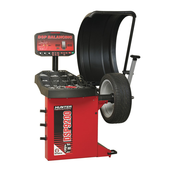
Page 13: Dsp9200 Components
1.3 DSP9200 Components 1. Getting Started x 9 DSP9200 Series Balancer Operation Instructions... -
Page 14: Standard Accessories
8. 223-68-1 Pressure Ring 9. 65-72-2 Calibration Weight NOTE: Hunter wheel balancers do not include a standardized set of mounting adaptors. For optional accessories, refer to Wheel Balancer Brochure, Form 3203T. 10 x 1. Getting Started DSP9200 Series Balancer Operation Instructions... -
Page 15: Operating The Control Panel
Press the “Enter” button to enter information and to begin a procedure that has been selected, or to “Store/Recall” wheels. Refer to “Storing and Recalling Wheels,” page 55. 1. Getting Started x 11 DSP9200 Series Balancer Operation Instructions... -
Page 16: Using Wheel Dimension Control Knobs
Changes to wheel dimensions are made by rotating the knobs. The control knobs are digital encoder design and variable speed. Rotating slowly will change increments in single digits. Rotating quickly will advance and move increments at an increased rate. 12 x 1. Getting Started DSP9200 Series Balancer Operation Instructions... -
Page 17: Balancing Overview
This is not a recommended practice and usually insures the assembly is not properly dynamically balanced. The assembly may then experience side-to-side imbalance while in motion, causing a shimmy condition and objectionable vibration. 2. Balancing Overview x 13 DSP9200 Series Balancer Operation Instructions... -
Page 18: Dynamic Imbalance
TOP VIEW IMBALANCE WOBBLE (LATERAL TWIST OR TORQUE) IMBALANCE FORCE (UP & DOWN) ZERO STATIC IMBALANCE (UP & DOWN) + ZERO COUPLE IMBALANCE (WOBBLE) _____________________________________ = ZERO DYNAMIC BALANCE 14 x 2. Balancing Overview DSP9200 Series Balancer Operation Instructions... -
Page 19: Static And Dynamic Imbalance Sensitivity
DIAMETER For static balancing, it is recommended that the adhesive weight be placed as close to the center of the wheel as possible to reduce residual dynamic imbalance. 2. Balancing Overview x 15 DSP9200 Series Balancer Operation Instructions... -
Page 20: Identifying The Dynamic Balance Weight Planes
RIM LIP / RIM LIP RIM LIP / INNER RIM SURFACE INNER RIM SURFACE INNER TIRE SURFACE In “STANDARD BALANCE” mode, using only clip-on weights, left and right planes are input as follows: 16 x 2. Balancing Overview DSP9200 Series Balancer Operation Instructions... - Page 21 In “ADHESIVE WEIGHTS BALANCE” mode, left and right planes are input as follows: In “PATCH BALANCE” mode, using patch weights, left and right planes are input as follows: LEFT DISTANCE DIAMETER RIGHT DISTANCE 2. Balancing Overview x 17 DSP9200 Series Balancer Operation Instructions...
-
Page 22: On-Vehicle Wheel Mounting Methods
To verify if the wheel is lug centric: Remove the lug nuts (or bolts) and try to move the wheel up/down and side/side on the hub. A lug centric wheel will display noticeable movement. 18 x 2. Balancing Overview DSP9200 Series Balancer Operation Instructions... -
Page 23: Balancing A Wheel
Slowly roll the wheel towards you while tightening the wing nut. This improves accurate wheel centering, since the wheel is allowed to roll up the taper of the cone as opposed to forcing it to slide up the cone. 3. Balancing a Wheel x 19 DSP9200 Series Balancer Operation Instructions... -
Page 24: Front/Back Cone Mounting
STANDARD STEEL WHEEL RIM STANDARD WHEEL WHEEL MOUNTING CONE SPINDLE SHAFT WING NUT CAPTIVATED SPRING PLASTIC INSIDE CLAMPING SURFACE 20 x 3. Balancing a Wheel DSP9200 Series Balancer Operation Instructions... -
Page 25: Using Plastic Wheel Mounting Washer
WING NUT CAPTIVATED PLASTIC SPRING The scratch guard may be installed on the clamping cup to protect aluminum rims from being marred, but should not be used on steel wheels. 3. Balancing a Wheel x 21 DSP9200 Series Balancer Operation Instructions... - Page 26 (2) use of optional wheel lift to position heavy wheel onto shaft and cone. This helps the wheel to overcome gravity against the hub or spacer. 22 x 3. Balancing a Wheel DSP9200 Series Balancer Operation Instructions...
-
Page 27: Cone/Flange Plate Mounting
This statement is true for many wheels including hub centric wheels. That is why a flange plate and back cone may be more accurate and repeatable, regardless of whether the wheel is lug centric or hub centric. 3. Balancing a Wheel x 23 DSP9200 Series Balancer Operation Instructions... -
Page 28: Using The Pressure Ring And Spacers
These light truck spacers are designed to build a larger pocket when using extra large truck cones. It also provides a location for the centering pins found on some dual wheel configurations. 24 x 3. Balancing a Wheel DSP9200 Series Balancer Operation Instructions... -
Page 29: Centeringcheck
The display momentarily flashes “FAIL” then shows “---” instead of weights. Check wheel to adaptor fitment and centering. Retry. 3. Balancing a Wheel x 25 DSP9200 Series Balancer Operation Instructions... -
Page 30: Measuring The Wheel With Inner And Outer Auto Dataset Arms
A more accurate wheel balance will result if the reading is not manually (knob) adjusted to the nominal wheel diameter. 26 x 3. Balancing a Wheel DSP9200 Series Balancer Operation Instructions... -
Page 31: Mixed Weights And Two Adhesive Weights (Inputting Distance And Diameter For Both Planes)
The dimension digits will now blink a prompt for optional “Split Spoke ” mode. Refer to “Split Spoke® Feature,” page 53, or return the arm to the home position. 3. Balancing a Wheel x 27 DSP9200 Series Balancer Operation Instructions... -
Page 32: Manually Setting Wheel Dimensions
The distance knob (1) is used to input the distance from the balancer to a weight plane. The width knob (2) is used to input the distance from the left weight plane to the right weight plane. 28 x 3. Balancing a Wheel DSP9200 Series Balancer Operation Instructions... -
Page 33: Measuring The Wheel At The Inner Rim Lip (Clip-On Weight)
(B) below. In either case, the balancer will compensate for this and provide accurate weight locations. TIRE WHEEL RIM LIP DATASET £ ARM POINTER DISK 3. Balancing a Wheel x 29 DSP9200 Series Balancer Operation Instructions... -
Page 34: Measuring Wheel Width With Rim Width Calipers
The balancer prevents the operator from locating the two wheel weights too close together to provide a correct dynamic balance. 30 x 3. Balancing a Wheel DSP9200 Series Balancer Operation Instructions... -
Page 35: Measuring The Inside Wheel Diameters (For Adhesive Weights)
Measure the rim inside diameters at the same location where the wheel weight is to be placed and set the wheel diameter knob to the measurement: 3. Balancing a Wheel x 31 DSP9200 Series Balancer Operation Instructions... -
Page 36: Locating The Wheel Weights At The Top Dead Center ("Tdc") And Bottom Dead Center ("Bdc")
180 degrees from TDC (Bottom Dead Center - BDC). BLINKING BLINKING (BDC) (TDC) ON LEFT PLANE WEIGHT AT TDC (APPLIED) RIGHT PLANE WEIGHT (APPLIED) 32 x 3. Balancing a Wheel DSP9200 Series Balancer Operation Instructions... -
Page 37: Standard Balancing Procedure (Clip-On Weights)
Measure and enter the distance to the wheel inner rim lip and rim diameter as shown below: “P195/75R-15” Measurement can be input automatically, if the DSP9200 is equipped with the ® optional auto inner and/or outer Dataset arms. 3. Balancing a Wheel x 33 DSP9200 Series Balancer Operation Instructions... - Page 38 ” button to split weight. Find TDC for right plane and attach weight. RIGHT PLANE TDC ® If necessary, use the “Right Plane Split Weight ” button to split weight. 34 x 3. Balancing a Wheel DSP9200 Series Balancer Operation Instructions...
-
Page 39: Static / Standard Balancing Procedure (Clip-On Weight)
“Static/Dynamic” button to select STATIC Press the “Standard/ALU” button until both clip-on weights are blinking. Measure and enter the rim diameter of static plane weight location as shown below: 3. Balancing a Wheel x 35 DSP9200 Series Balancer Operation Instructions... -
Page 40: Adhesive Weight Procedures (Combination Of Clip-On & Adhesive Weights, Or Two Adhesive)
Adhesive inner (backside of wheel, BDC) * Select front side weight placement mode by entering either clip-on/adhesive or ® adhesive/adhesive mode, then move the optional outer Dataset arm away from the home position. 36 x 3. Balancing a Wheel DSP9200 Series Balancer Operation Instructions... - Page 41 Measure and enter the dimensions of the left plane weight location as shown below: CLIP-ON/ADHESIVE ADHESIVE/ADHESIVE Press the “Next” button to change display to show right plane weight dimensions. Measure and enter the dimensions of right plane weight location as shown below: 3. Balancing a Wheel x 37 DSP9200 Series Balancer Operation Instructions...
- Page 42 BDC, then ® trigger the Dataset arm to begin Servo Aided Weight Placement. Refer to “Servo Aided Weight Placement,” page 47. 38 x 3. Balancing a Wheel DSP9200 Series Balancer Operation Instructions...
- Page 43 RIGHT PLANE BDC (BLINKING) ® If necessary, use the “Right Plane Split Weight ” to split weight. Verify balance condition by spinning again. Display should show “zero.” Balancing procedure is complete. 3. Balancing a Wheel x 39 DSP9200 Series Balancer Operation Instructions...
- Page 44 WHEN RIGHT WEIGHT IS TO BE PLACED AS ILLUSTRATED, INPUT RIGHT PLANE DIMENSIONS AS FOLLOWS: 40 x 3. Balancing a Wheel DSP9200 Series Balancer Operation Instructions...
-
Page 45: Static / Alu Balancing Procedure (Adhesive Weight)
Close safety hood and spin wheel. After wheel stops, raise safety hood. The 360 degree weight angle display can be used to place the adhesive weight at Bottom Dead Center (BDC) for easier and more accurate placement than the 3. Balancing a Wheel x 41 DSP9200 Series Balancer Operation Instructions... - Page 46 180 degrees on the wheel. Remount the tire/wheel assembly on the balancer with valve stem at TDC and press “Enter.” Close safety hood and spin wheel. After wheel stops, raise the safety hood. 42 x 3. Balancing a Wheel DSP9200 Series Balancer Operation Instructions...
-
Page 47: Opt-1 Optimizing Tire & Wheel Imbalances
Deflate tire, loosen the tire beads from the wheel, and rotate tire on the wheel to lineup the two marks. OPT-2 balancing procedure is complete. Balance the tire/wheel assembly. Refer to the desired balance procedure. 3. Balancing a Wheel x 43 DSP9200 Series Balancer Operation Instructions... -
Page 48: Patch Balance Procedures
“Static/Dynamic” button to select STATIC mode. Press the “Standard/ALU” button twice to select adhesive weight mode. Measure inside tire diameter using a tape measure or tool, 221-527-1, just below tread depth as shown below: 44 x 3. Balancing a Wheel DSP9200 Series Balancer Operation Instructions... -
Page 49: Dynamic Patch Balance (Two Weighted Balance Patches)
LEFT PLANE RIGHT PLANE NOTE: Weighted balance patches should be installed only in tread area. Do not install weighted balance patches near sidewall or shoulder of tire. Mount wheel. 3. Balancing a Wheel x 45 DSP9200 Series Balancer Operation Instructions... - Page 50 The blinking weights indicate that a second spin and additional weight(s) may be required to get zero imbalance. Refer to “Correcting Large Imbalances,” page 52. 46 x 3. Balancing a Wheel DSP9200 Series Balancer Operation Instructions...
-
Page 51: Balancing Features And Options
Maintaining that distance, rotate the Dataset arm toward the inner rim surface, and then apply the adhesive weights to the rim by pressing the adhesive weight release tab. 4. Balancing Features and Options x 47 DSP9200 Series Balancer Operation Instructions... -
Page 52: Inside Of Wheel (Single Row Of Adhesive Weights)
3 ounces. Make each strip of weights as close as possible to one-half the required amount of weight. WEIGHTS ON RIGHT EDGE OF WEIGHT PLANE AS MEASURED BY DATASET® 48 x 4. Balancing Features and Options DSP9200 Series Balancer Operation Instructions... -
Page 53: Quick-Thread™ Feature
Servo-Push allows pushing the wheel (approximately 1/8 of a revolution) to cause the intelligent DC motor drive to automatically rotate the wheel to the next weight placement position. Pressing the “START” key may still be used for this function. 4. Balancing Features and Options x 49 DSP9200 Series Balancer Operation Instructions... -
Page 54: Spindle-Lok Feature
“ratcheting” sound is occurring (at minimum value) for this to occur. When the balancer is first turned “ON,” the diameter digits will default to zero (the loose hub detect feature is overridden). 50 x 4. Balancing Features and Options DSP9200 Series Balancer Operation Instructions... -
Page 55: Blinding And Rounding
4. Balancing Features and Options x 51 DSP9200 Series Balancer Operation Instructions... -
Page 56: Split Weight Operation
(as illustrated below) using the TDC display indicators. Splitting 1 Large Weight into 3 Smaller Weights REQUIRED (3) WEIGHTS SINGLE WEIGHT EQUIVALENT TO 6.75 OZ 6.75 oz 2.25 oz 2.75 oz 2.75 oz 52 x 4. Balancing Features and Options DSP9200 Series Balancer Operation Instructions... -
Page 57: Split Spoke Feature
® Return the optional inner Dataset arm to the home position. Close safety hood. Press the green “Start” button if “Hood Autostart” is disabled. Continue the balancing procedure. 4. Balancing Features and Options x 53 DSP9200 Series Balancer Operation Instructions... -
Page 58: Placing Hidden Weight Forward Of Obstructions
“Start” button with the safety hood in the raised position and the DSP9200 will servo to the location for the second spoke. Attach the appropriate weight as displayed on the console. Verify balance condition by spinning again. 54 x 4. Balancing Features and Options DSP9200 Series Balancer Operation Instructions... -
Page 59: Automatic Weight Recalculation And Dimension Preservation
“Next” button until stored wheel 1, 2, 3, or 4 is selected. Press the “Enter” button briefly (less than two seconds) to recall stored wheel dimensions and SETUP information. 4. Balancing Features and Options x 55 DSP9200 Series Balancer Operation Instructions... - Page 60 56 x 4. Balancing Features and Options DSP9200 Series Balancer Operation Instructions...
-
Page 61: Maintenance And Calibration
“920” Indicates a DSP9200 (No Auto Dataset arms) ® “92d” Indicates a DSP9200 (Inner Auto Dataset arm only) ® “2dd” Indicates a DSP9200 (Inner and Outer Auto Dataset arms) 5. Maintenance and Calibration x 57 DSP9200 Series Balancer Operation Instructions... -
Page 62: Calibration Procedures
Check angle accuracy by verifying that the cal weight stops at TDC (12 o’clock position). If cal weight is in a position other than TDC, perform calibration procedure. Press the “Next” button to show weights. The Quick Cal™ Check is complete. 58 x 5. Maintenance and Calibration DSP9200 Series Balancer Operation Instructions... -
Page 63: Balancer Calibration
Install cal weight on left side of hub faceplate in either hole, align cal weight at TDC, and press the “Enter” button. Spin. Move cal weight to right side of hub faceplate in same hole. Spin, display reads “CAL RDY.” 5. Maintenance and Calibration x 59 DSP9200 Series Balancer Operation Instructions... -
Page 64: Inner Dataset ® Arm (Calibration Tool, 221-672-1, Required)
“2.” Tap the foot pedal once or press “Enter.” ® Move the inner Dataset arm to upward position “3.” Tap the foot pedal once or press “Enter.” 60 x 5. Maintenance and Calibration DSP9200 Series Balancer Operation Instructions... - Page 65 “Enter.” ® If optional outer Dataset arm is not installed, calibration is complete. If optional outer ® ® Dataset arm is installed, refer to “Outer Dataset Arm,” page 62. 5. Maintenance and Calibration x 61 DSP9200 Series Balancer Operation Instructions...
-
Page 66: Outer Dataset ® Arm (Calibration Tool, 221-672-1, Required)
“RDY” is displayed near the inner arm graphic ® to indicate that the inner Dataset calibration passed. “RDY --]” is displayed on the ® weight digits to indicate that the outer Dataset calibration passed. 62 x 5. Maintenance and Calibration DSP9200 Series Balancer Operation Instructions... -
Page 67: Glossary
A device used much like a doctor’s stethoscope and is for noise diagnosis problems only. Forced Vibration Vibrates when energy is applied. Free Vibration Continues to vibrate after the outside energy stops. 6. Glossary x 63 DSP9200 Series Balancer Operation Instructions... - Page 68 Radial Runout A condition where the tire and wheel assembly is slightly out of round forcing the spindle to move up and down as the vehicle rolls along a smooth surface. 64 x 6. Glossary DSP9200 Series Balancer Operation Instructions...
- Page 69 Wheel Offset The measured distance between the mounting face of the wheel and the centerline of the rim. Wheel Width Dimension measured on the inside of the rim between the bead seats. 6. Glossary x 65 DSP9200 Series Balancer Operation Instructions...
- Page 70 Busses and RVs are discussed. Hunter University’s eLearning courses are designed for all student levels and can be used as an integral supplement to instructor-led training courses. In-depth information, detailed graphics, video and modular segments assist the participant in expanding their knowledge base at a self-determined level.
Need help?
Do you have a question about the DSP9200 Series and is the answer not in the manual?
Questions and answers