NordicTrack Grand Tour User Manual
Hide thumbs
Also See for Grand Tour:
- User manual (35 pages) ,
- User manual (40 pages) ,
- User manual (40 pages)
Table of Contents
Advertisement
Model No. NTEVEX89916.0
Serial No.
USER'S MANUAL
Write the serial number in the space
above for reference.
Serial Number
Decal
CUSTOMER SERVICE
UNITED KINGDOM
Call: 0330 123 1045
From Ireland: 053 92 36102
Website: www.iconsupport.eu
E-mail: csuk@iconeurope.com
Write:
ICON Health & Fitness, Ltd.
Unit 1D, The Gateway
Fryers Way, Silkwood Park
OSSETT
WF5 9TJ
UNITED KINGDOM
AUSTRALIA
Call: 1800 993 770
E-mail: australiacc@iconfitness.com
Write:
ICON Health & Fitness
PO Box 635
WINSTON HILLS NSW 2153
AUSTRALIA
CAUTION
Read all precautions and
instructions in this manual before
using this equipment. Keep this
manual for future reference.
www.iconeurope.com
Advertisement
Table of Contents

Related Manuals for NordicTrack Grand Tour


Summary of Contents for NordicTrack Grand Tour
- Page 1 Model No. NTEVEX89916.0 Serial No. USER’S MANUAL Write the serial number in the space above for reference. Serial Number Decal CUSTOMER SERVICE UNITED KINGDOM Call: 0330 123 1045 From Ireland: 053 92 36102 Website: www.iconsupport.eu E-mail: csuk@iconeurope.com Write: ICON Health & Fitness, Ltd. Unit 1D, The Gateway Fryers Way, Silkwood Park OSSETT...
-
Page 2: Table Of Contents
376541 NORDICTRACK is a registered trademark of ICON Health & Fitness, Inc. IFIT is a registered trademark of ICON Health & Fitness, Inc. Google Maps is a trademarks of Google Inc. The BLUETOOTH word mark and logos are ®... -
Page 3: Important Precautions
IMPORTANT PRECAUTIONS WARNING: To reduce the risk of burns, fire, electric shock, or injury to persons, read all important precautions and instructions in this manual and all warnings on your exercise bike before using your exercise bike. ICON assumes no responsibility for personal injury or property damage sustained by or through the use of this product. - Page 4 15. The exercise bike should not be used 17. Always keep your back straight while using by persons weighing more than 330 lbs. the exercise bike; do not arch your back. (150 kg). 18. Over exercising may result in serious injury 16.
-
Page 5: Before You Begin
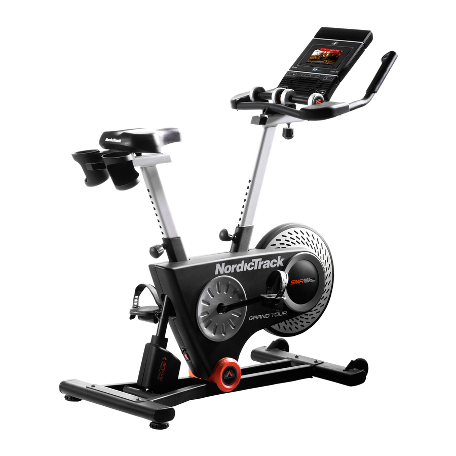
GRAND TOUR exercise bike is designed to let you Before reading further, please familiarize yourself with enjoy the outdoor cycling experience indoors. -
Page 6: Part Identification Chart
PART IDENTIFICATION CHART Use the drawings below to identify the small parts needed for assembly. The number in parentheses below each drawing is the key number of the part, from the PART LIST near the end of this manual. The number following the key number is the quantity needed for assembly. -
Page 7: Assembly
ASSEMBLY • Assembly requires two persons. • In addition to the included tool(s), assembly requires the following tools: • Place all parts in a cleared area and remove the one Phillips screwdriver packing materials. Do not dispose of the packing materials until you finish all assembly steps. -
Page 8: Front Of The Base (1), Remove The Screws From
3. If there is a shipping support attached to the front of the Base (1), remove the screws from the shipping support, and discard the screws and the shipping support. Attach the Front Stabilizer (22) to the Base (1) with two M10 x 58mm Screws (74). 4. - Page 9 6. Locate the Post Knob (47) on the rear of the Frame (2). Loosen and pull the Post Knob. Next, insert the Seat Post (3) into the Frame (2), and release the Post Knob (47) into one of the adjustment holes (A) in the Seat Post. Make sure that the Post Knob is in an adjustment hole.
- Page 10 8. Have a second person hold the Handlebar Post (6) near the Frame (2). Locate the long wire tie (B) in the Handlebar Post (6). Tie the lower end of the long wire tie to the Main Wire (68). Next, locate the middle of the long wire tie (C) in the access hole (D) in the Handlebar Carriage (99).
- Page 11 10. Have a second person hold the Handlebar (7) near the Handlebar Carriage (99). Locate the remaining wire tie (F) in the Handlebar Carriage (99). Tie the indicated end of the wire tie to the two wires on the Handlebar (7). Next, pull the other end of the wire tie (F) until the two wires are routed through the Handlebar Carriage (99).
- Page 12 13. Have a second person hold the Console (9) near the Console Bracket (33). Avoid pinching Connect the console wires to the Main Wire (68), the wires to the Ground Wire (111), and to the two wires (G) from the Handlebar (7); make sure to con- nect the console wire that has an “R”...
- Page 13 15. Set the two Hand Weights (15) on the Hand Weight Rest (83) and on the Armrests (69, 72). 16. Identify the Right Pedal (62). Using the included flat wrench tool, firmly tighten the Right Pedal (62) clockwise into the Right Crank Arm (64).
-
Page 14: How To Use The Exercise Bike
HOW TO USE THE EXERCISE BIKE HOW TO PLUG IN THE POWER CORD Follow the steps below to plug in the power cord. This product must be earthed. If it should 1. Plug the indicated end of the power cord into the malfunction or break down, earthing provides a path of socket on the frame. - Page 15 HOW TO ADJUST THE EXERCISE BIKE How to Adjust the Handlebar Post The exercise bike can be adjusted to promote correct To adjust the height form and to ensure proper training of the muscles. of the handlebar Note: Make adjustments in small increments, post, loosen and and then pedal the exercise bike to test the pull the post knob,...
- Page 16 HOW TO LEVEL THE EXERCISE BIKE HOW TO USE THE TABLET HOLDER If the exercise bike IMPORTANT: The tablet holder is designed for use with most full-size tablets. Do not place any other rocks slightly on electronic device or object in the tablet holder. your floor during use, turn one or both of the level-...
- Page 17 CONSOLE DIAGRAM MAKE YOUR FITNESS GOALS A REALITY WITH Upload your workout results to the iFit cloud IFIT.COM and track your accomplishments. With your new iFit-compatible fitness equipment, you can use an array of features on iFit.com to make your Set calorie, time, distance, or watts goals fitness goals a reality: for your workouts.
-
Page 18: Part List
FEATURES OF THE CONSOLE HOW TO TURN ON THE POWER The advanced console offers an array of features IMPORTANT: If the exercise bike has been exposed to cold temperatures, allow it to warm to room tem- designed to make your workouts more effective and perature before you turn on the power. - Page 19 HOW TO USE THE TOUCH SCREEN NETWORK MODE on page 30 to connect the console to your wireless network. The console features a tablet with a full-color touch 2. Check for firmware updates. screen. The following information will help you become familiar with the tablet’s advanced technology: First, see step 1 on page 26 and step 2 on page •...
- Page 20 HOW TO USE THE MANUAL MODE Note: After you press a button, it will take a moment for the frame to reach the selected 1. Touch the screen or begin pedaling to activate incline level. You will hear the incline motor the console.
- Page 21 6. Do intervals if desired. 8. Turn on the fan if desired. During a workout, you can use the interval screen The fan has several to measure your performance for short periods of speed settings, includ- time. To select the interval screen, simply flick or ing an auto mode.
- Page 22 HOW TO USE AN ONBOARD WORKOUT During the workout, the profiles will show your progress. To view the profiles, flick or slide the 1. Touch the screen or begin pedaling to activate screen. the console. During some workouts, the screen will show a map See HOW TO TURN ON THE POWER on of the route and a marker indicating your prog- page 18.
- Page 23 6. Do intervals if desired. To pause the workout, touch either the back button or the home button at the bottom of the screen. To continue the workout, touch the Resume button. To See step 6 on page 21. end the workout, touch the End Workout button. 7.
- Page 24 HOW TO USE A SET-A-GOAL WORKOUT If the resistance level and/or incline level for the current segment is too high or too low, you can 1. Touch the screen or begin pedaling to activate manually override the setting by pressing the the console.
- Page 25 HOW TO USE AN IFIT WORKOUT To switch users within your iFit account, touch the user button at the bottom of the screen. If more To use an iFit workout, the console must be connected than one user is associated with your iFit account, to a wireless network (see HOW TO USE THE a list of users will appear.
- Page 26 7. Follow your progress. HOW TO USE THE EQUIPMENT SETTINGS MODE See step 5 on page 20. The screen may also IMPORTANT: Some of the features described may not be enabled. Occasionally, a firmware update may show a map of the route and a marker indicating your progress.
- Page 27 5. Enable or disable the internet browser. 9. Select a language. To enable or disable the internet browser, first To select a language, touch the Language button touch the Browser button. Next, touch the Enable and select the desired language. Then, follow the checkbox or the Disable checkbox.
- Page 28 13. Select an update time. HOW TO USE THE MAINTENANCE MODE To select a time for automatic console updates, IMPORTANT: Some of the features described may not be enabled. Occasionally, a firmware update may touch the Update Time button and select the desired time.
- Page 29 5. View machine information. Note: Occasionally, a firmware update may cause your console to function slightly differently. These updates are always designed to improve your train- Touch the Machine Info button to view information ing experience. about your exercise bike. After you view the infor- mation, touch the back button on the screen.
- Page 30 HOW TO USE THE WIRELESS NETWORK MODE When a list of networks appears, touch the desired network. Note: You will need to know your network The console features a wireless network mode that name (SSID). If your network has a password, you allows you to set up a wireless network connection.
- Page 31 HOW TO USE THE SOUND SYSTEM To use the keyboard, see HOW TO USE THE TOUCH SCREEN on page 19. To play music or audio books through the console sound system while you exercise, plug a 3.5 mm male To enter a different web address in the URL bar, first, to 3.5 mm male audio cable (not included) into the slide your finger down the screen to view the URL bar, jack on the console and into a jack on your personal...
-
Page 32: Maintenance And Troubleshooting
MAINTENANCE AND TROUBLESHOOTING HOW TO MAINTAIN THE EXERCISE BIKE See the inset drawing at the left. Locate the Reed Switch (35). Turn the Left Crank Arm (63) until a Regular maintenance is important for optimal Magnet (55) is aligned with the Reed Switch. Next, loosen the M5 x 16mm Screw (76), slide the Reed performance and to reduce wear. - Page 33 HOW TO ADJUST THE DRIVE BELT See the inset drawing at the left. Tighten the Idler Adjustment Screw (39) slightly. If the pedals slip while you are pedaling, the drive belt may need to be adjusted. Before you adjust the drive Then, plug in the power cord, and pedal the exercise belt, unplug the power cord.
-
Page 34: Exercise Guidelines
EXERCISE GUIDELINES Aerobic Exercise—If your goal is to strengthen your WARNING: cardiovascular system, you must perform aerobic Before beginning this exercise, which is activity that requires large amounts or any exercise program, consult your physi- of oxygen for prolonged periods of time. For aerobic cian. - Page 35 SUGGESTED STRETCHES The correct form for several basic stretches is shown at the right. Move slowly as you stretch; never bounce. 1. Toe Touch Stretch Stand with your knees bent slightly and slowly bend forward from your hips. Allow your back and shoulders to relax as you reach down toward your toes as far as possible.
- Page 36 PART LIST Model No. NTEVEX89916.0 R0416A Key No. Qty. Description Key No. Qty. Description Base Board Bracket Frame Standoff Seat Post Crank Pulley Seat Carriage Crank Seat Magnet Handlebar Post M8 x 16mm Screw Handlebar Bearing Water Bottle Holder Snap Ring Console Frame Bushing Tablet Holder...
- Page 37 Key No. Qty. Description Key No. Qty. Description M4 x 10mm Flange Screw M4 x 45mm Screw Handlebar Carriage Cap M8 x 3mm Washer M6 x 20mm Screw M4 x 12mm Ground Screw 38mm Washer Ground Wire M4 x 16mm Flange Screw –...
- Page 38 EXPLODED DRAWING A Model No. NTEVEX89916.0 R0416A...
- Page 39 EXPLODED DRAWING B Model No. NTEVEX89916.0 R0416A...
-
Page 40: Ordering Replacement Parts
ORDERING REPLACEMENT PARTS To order replacement parts, please see the front cover of this manual. To help us assist you, be prepared to provide the following information when contacting us: • the model number and serial number of the product (see the front cover of this manual) •...
Need help?
Do you have a question about the Grand Tour and is the answer not in the manual?
Questions and answers