Table of Contents
Advertisement
nordictrack.com
USER'S MANUAL
Model No. NTEX70417.2
Serial No.
Write the serial number in the space
above for reference.
Serial Number
Decal
ACTIVATE YOUR
WARRANTY
To register your product and
activate your warranty today,
go to my.nordictrack.com.
CUSTOMER CARE
For service at any time, go to
support.nordictrack.com.
Or call 1-800-TO-BE-FIT
(1-800-862-3348)
Mon.–Fri. 6 a.m.–6 p.m. MT
Sat. 8 a.m.–12 p.m. MT
Please do not contact the store.
CAUTION
Read all precautions and
instructions in this manual before
using this equipment. Keep this
manual for future reference.
Advertisement
Table of Contents

Related Manuals for NordicTrack GRAND TOUR PRO


Summary of Contents for NordicTrack GRAND TOUR PRO
- Page 1 Serial Number Decal ACTIVATE YOUR WARRANTY To register your product and activate your warranty today, go to my.nordictrack.com. CUSTOMER CARE For service at any time, go to support.nordictrack.com. Or call 1-800-TO-BE-FIT (1-800-862-3348) Mon.–Fri. 6 a.m.–6 p.m. MT Sat.
-
Page 2: Table Of Contents
Note: The decal(s) may not be shown at actual size. 376541 NORDICTRACK and IFIT are registered trademarks of ICON Health & Fitness, Inc. The Bluetooth word mark ® and logos are registered trademarks of Bluetooth SIG, Inc. and are used under license. Google Maps is a trade- mark of Google LLC. -
Page 3: Important Precautions
IMPORTANT PRECAUTIONS WARNING: To reduce the risk of burns, fire, electric shock, or injury to persons, read all important precautions and instructions in this manual and all warnings on your exercise bike before using your exercise bike. ICON assumes no responsibility for personal injury or property damage sustained by or through the use of this product. - Page 4 STANDARD SERVICE PLANS...
-
Page 5: Before You Begin
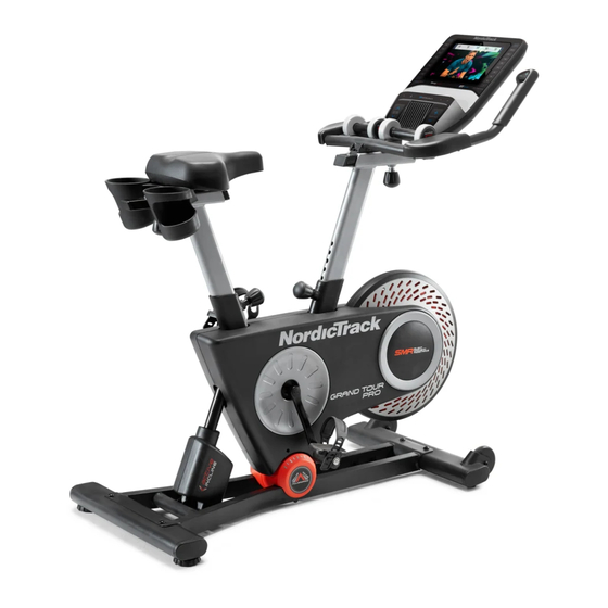
NORDICTRACK GRAND TOUR PRO exercise ® bike. The GRAND TOUR PRO exercise bike is unlike reading this manual, please see the front cover of this any ordinary exercise bike. With full adjustability, an manual. To help us assist you, note the product model advanced console, an incline system allows you to number and serial number before contacting us. -
Page 6: Part Identification Chart
PART IDENTIFICATION CHART Use the drawings below to identify the small parts needed for assembly. The number in parentheses below each drawing is the key number of the part, from the PART LIST near the end of this manual. The number following the key number is the quantity needed for assembly. -
Page 7: Assembly
• Left parts are marked “L” or “Left” and right parts power tools. are marked “R” or “Right.” • To identify small parts, see page 6. 1. Go to my.nordictrack.com on your computer and register your product. • documents your ownership • activates your warranty •... - Page 8 3. If there is a shipping support attached to the front of the Base (1), remove the screws from the shipping support, and discard the screws and the shipping support. Then, attach the Front Stabilizer (22) to the Base (1) with two M10 x 58mm Screws (74). 4.
- Page 9 6. Locate the Post Knob (47) on the rear of the Frame (2). Loosen and pull the Post Knob. Next, orient a Post Bushing (42) as shown. Insert the Post Bushing into the Frame (2). Make sure that the tabs (A) on the Post Bushing are in the holes (B) in the Frame.
- Page 10 8. Orient a Post Bushing (42) as shown and hold it near the Frame (2). Insert the Main Wire (68) upward through the Post Bushing. Next, locate the Post Knob (47) on the front of the Frame (2). Loosen and pull the Post Knob, and then insert the Post Bushing into the Frame.
- Page 11 10. Tip: Avoid pinching the Main Wire (68) during this step. Loosen and pull the Post Knob (47). Next, insert the Handlebar Post (6) into the Frame (2), and release the Post Knob (47) into the lowest adjustment hole (H) in the Handlebar Post.
- Page 12 12. Loosen the Handlebar Knob (95). Next, slide the Handlebar Carriage (99) forward as far as Avoid pinching possible. Then, tighten the Handlebar Knob. the wires Tip: Avoid pinching the wires. Attach the Handlebar (7) to the Handlebar Carriage (99) with four M6 x 20mm Screws (103);...
- Page 13 15. Attach the Tablet Holder (10) to the Console (9) with four Tablet Holder Screws (82); start all the Tablet Holder Screws, and then tighten them. 16. Set the two Hand Weights (15) on the Hand Weight Rest (83) and on the Armrests (69, 72). 17.
-
Page 14: How To Use The Exercise Bike
HOW TO USE THE EXERCISE BIKE HOW TO PLUG IN THE POWER CORD A temporary adapter (C) may This product must be grounded. If it should mal- be used to con- function or break down, grounding provides a path of nect the power least resistance for electric current to reduce the risk cord to a 2-pole... - Page 15 HOW TO ADJUST THE EXERCISE BIKE How to Adjust the Handlebar Post The exercise bike can be adjusted to promote correct To adjust the height form and to ensure proper training of the muscles. of the handle- Note: Make adjustments in small increments, bar post, loosen and then pedal the exercise bike to test the and pull the post...
- Page 16 HOW TO LEVEL THE EXERCISE BIKE HOW TO USE THE TABLET HOLDER If the exercise bike IMPORTANT: The tablet holder (O) is designed for use with most full-size tablets. Do not place rocks slightly on any other electronic device or object in the tablet your floor during use, turn one or holder.
-
Page 17: How To Use The Console
HOW TO USE THE CONSOLE CONSOLE DIAGRAM FEATURES OF THE CONSOLE When you use the manual mode of the console, you can change the resistance of the pedals and the incline The advanced console offers an array of features of the frame with the touch of a button. designed to make your workouts more effective and enjoyable. - Page 18 HOW TO TURN ON THE POWER HOW TO USE THE TOUCH SCREEN IMPORTANT: If the exercise bike has been exposed The console features a tablet with a full-color touch to cold temperatures, allow it to warm to room tem- screen. The following information will help you use the perature before you turn on the power.
- Page 19 HOW TO SET UP THE CONSOLE 5. Check for firmware updates. Before you use the exercise bike for the first time, set First, touch the menu button (three horizontal lines symbol), touch Settings, touch Maintenance, and up the console. then touch Update. The console will check for firm- 1.
- Page 20 HOW TO USE THE MANUAL MODE 4. Follow your progress. 1. Touch the screen or press any button on the The console offers several display modes. The console to turn on the console. display mode that you select will determine which workout information is shown.
- Page 21 6. Turn on the fan if desired. button on the screen. Slide or flick the screen to scroll upward or downward if necessary. The fan has several speed settings, includ- Note: To use a featured workout, the console must ing an auto mode. be connected to a wireless network (see HOW While the auto mode is TO CONNECT TO A WIRELESS NETWORK on...
- Page 22 If the resistance level and/or incline level is too When the workout ends, a workout summary will high or too low, you can manually override the appear on the screen. If desired, you can select setting by pressing the Resistance buttons or the options such as adding the workout to your sched- Incline/Decline buttons.
- Page 23 HOW TO CREATE A DRAW-YOUR-OWN-MAP If you make a mistake, touch Undo in the map WORKOUT options. 1. Touch the screen or press any button on the The screen will display the elevation and distance console to turn on the console. statistics for your workout.
- Page 24 HOW TO USE AN IFIT WORKOUT 4. Select an iFit workout that you have previously added to your schedule on iFit.com. To use an iFit workout, the console must be connected IMPORTANT: Before iFit workouts will load, you to a wireless network (see HOW TO CONNECT TO A must add them to your schedule on iFit.com WIRELESS NETWORK on page 26).
- Page 25 HOW TO CHANGE CONSOLE SETTINGS 3. Customize the unit of measurement and other settings. IMPORTANT: Some of the settings and features described may not be enabled. Occasionally, a To customize the unit of measurement, the time firmware update may cause your console to function zone, or other settings, touch Equipment Info or slightly differently.
- Page 26 6. Calibrate the incline system. 3. Enable Wi-Fi. To calibrate the incline system, touch Maintenance, Make sure that Wi-Fi is enabled. If it is not ® touch Calibrate Incline, and then touch Begin. The enabled, touch the Wi-Fi toggle to enable it. frame will automatically rise to the maximum incline level, lower to the minimum incline level, and then 4.
- Page 27 HOW TO USE THE SOUND SYSTEM THE OPTIONAL CHEST HEART RATE MONITOR To play music or audio books through the console Whether your sound system while you exercise, plug a 3.5 mm male goal is to to 3.5 mm male audio cable (not included) into the burn fat or to jack on the console and into a jack on your personal strengthen your...
-
Page 28: Fcc Information
FCC INFORMATION This equipment has been tested and found to comply with the limits for a Class B digital device, pursuant to part 15 of the FCC Rules. These limits are designed to provide reasonable protection against harmful interference in a residential installation. This equipment generates, uses, and can radiate radio frequency energy and, if not installed and used in accordance with the instructions, may cause harmful interference to radio communications. -
Page 29: Maintenance And Troubleshooting
MAINTENANCE AND TROUBLESHOOTING HOW TO MAINTAIN THE EXERCISE BIKE on the back or the side of the console. Using a bent Regular maintenance is important for optimal paper clip, press and hold performance and to reduce wear. Inspect and properly the reset button inside the tighten all parts each time the exercise bike is used. - Page 30 HOW TO ADJUST THE REED SWITCH HOW TO ADJUST THE DRIVE BELT If the console does not display accurate feedback, the If the pedals slip while you are pedaling, the drive belt reed switch should be adjusted. Before you adjust the may need to be adjusted.
-
Page 31: Exercise Guidelines
EXERCISE GUIDELINES Aerobic Exercise—If your goal is to strengthen your WARNING: cardiovascular system, you must perform aerobic Before beginning this exercise, which is activity that requires large amounts or any exercise program, consult your physi- of oxygen for prolonged periods of time. For aerobic cian. -
Page 32: Part List
PART LIST Model No. NTEX70417.2 R0220A Key No. Qty. Description Key No. Qty. Description Base Board Bracket Frame Standoff Seat Post Crank Pulley Seat Carriage Crank Seat Magnet Handlebar Post M8 x 16mm Screw Handlebar Bearing Water Bottle Holder Snap Ring Console Frame Bushing Tablet Holder... - Page 33 Key No. Qty. Description Key No. Qty. Description M4 x 10mm Flange Screw M4 x 45mm Screw Handlebar Carriage Cap M8 x 3mm Washer M6 x 20mm Screw M4 x 12mm Ground Screw 38mm Washer Ground Wire M4 x 16mm Flange Screw Resistance Cable #8 x 16mm Screw –...
-
Page 34: Exploded Drawing
EXPLODED DRAWING A Model No. NTEX70417.2 R0220A... - Page 35 EXPLODED DRAWING B Model No. NTEX70417.2 R0220A...
-
Page 36: Ordering Replacement Parts
ORDERING REPLACEMENT PARTS To order replacement parts, please see the front cover of this manual. To help us assist you, be prepared to provide the following information when contacting us: • the model number and serial number of the product (see the front cover of this manual) •...
Need help?
Do you have a question about the GRAND TOUR PRO and is the answer not in the manual?
Questions and answers