Table of Contents
Advertisement
Quick Links
Advertisement
Table of Contents

Related Manuals for Advantech IPC-7220


Summary of Contents for Advantech IPC-7220
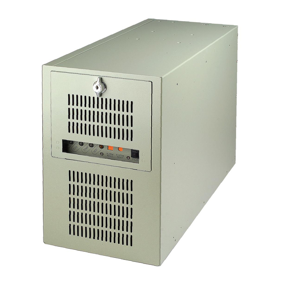
- Page 1 IPC-7220 Desktop/Wall mountable IPC Chassis User’s Manual...
- Page 2 Copyright This document is copyrighted, September 2004, by Advantech Co., Ltd. All rights are reserved. Advantech Co., Ltd. reserves the right to make improvements to the products described in this manual at any time without notice. No part of this manual may be reproduced, copied, translated or transmitted in any form or by any means without the prior written permission of Advantech Co., Ltd.
-
Page 3: Table Of Contents
..........4 OWER UPPLY PTIONS 1.5 D IPC-7220..........6 IMENSION OF Figure 1-1 Dimension of IPC-7220 ........ 6 CHAPTER 2 SYSTEM SETUP............8 2.1 R ............8 EMOVING THE COVER Figure 2-1 Removing the cover........8 2.2 I ........... 9 NSTALLING A MOTHERBOARD Figure 2-2 Installing a motherboard...... - Page 4 Table B-1 Passive Backplane Options ......32 B.2 I IPC-7220BP ........32 NSTALLATION OF Figure B-1: Installing of IPC-7220BP......33 APPENDIX C SAFETY INSTRUCTIONS ........36 C.1 E ............... 36 NGLISH C.1 G – ....37 ERMAN WICHTIGE ICHERHEISHINWEISE IPC-7220 User’s Manual...
- Page 5 General Information...
-
Page 6: Chapter 1 General Information
Outstanding mechanical designs The IPC-7220 can be placed on desktops or mounted bi-directionally, and using the supplied brackets, the IPC-7220 can be easily bottom or right-mounted onto most surfaces, such as walls or workbenches. The... -
Page 7: Specifications
1.2 Specifications • Construction: Heavy-duty steel • Disk drive capacity: two 3.5" (one front accessible and one internal) and two 5.25" bays • I/O interfaces on front panel: two USB and one PS/2 ports • I/O interfaces on rear panel: two D-SUB 9-pin openings •... -
Page 8: Power Supply Options
Input rating: 90 ~ 240 Vac @ 47 ~ 63 Hz (Full range) • Output voltage: +5 V @ 35 A, +3.3 V @ 25 A, +12 V @ 30A, -5 V @ 0.8 A, -12 V @ 1.0 A, +5 VSB @ 2 A IPC-7220 User’s Manual... - Page 9 • Minimum load: +5 V @ 3 A, +3.3 V @ 1 A, +12 V @ 2 A, +5 VSB @ 0.1 A • MTBF: 100,000 hours @ 25°C, full load • Safety: UL/cUL/TUV/FCC/CE/CB/CCC 1.4.4 400W ATX Redundant Power Supply (RPS-400ATX-Z) •...
-
Page 10: Dimension Of Ipc-7220
1.5 Dimension of IPC-7220 Figure 1-1 Dimension of IPC-7220 IPC-7220 User’s Manual... - Page 11 System Setup...
-
Page 12: Chapter 2 System Setup
IPC-7220. Please also refer to the Appendix A, Exploded Diagram, for the parts naming in this manual. 2.1 Removing the cover To remove the cover of the IPC-7220, please refer to Figure 2-1. Figure 2-1 Removing the cover IPC-7220 User’s Manual... -
Page 13: Installing A Motherboard
2.2 Installing a motherboard The IPC-7220 accepts both ATX and microATX motherboard. To install a motherboard, refer to Figure 2-2 and proceed as follows: Note: To avoid any component interfering between a motherboard and the chassis and to ensure the best air flow inside the chassis, it is highly recommended to choose a CPU cooler which is lower than 70 mm. -
Page 14: Adding Disk Drives
FDD/slim-CD-ROM, a 40-pin flat cable to an IDE HDD and a SATA cable to a SATA HDD. Insert the proper power connector into each drive. 5. Slide the drive bay back to the chassis and screw it. IPC-7220 User’s Manual... -
Page 15: Installing Plug-In Cards
Figure 2-3 Installing the drives 2.4 Installing plug-in cards The IPC-7220 can accept up to seven plug-in cards. To install a plug-in card, please refer to Figure 2-4 and proceed as follows: 1. Remove the two screws, which mount the hold-down clamp to the chassis, then take out the hold-down clamp. -
Page 16: Bi-Directional Mounting
Figure 2-4 Hold-down clamp installation 2.5 Bi-directional mounting Attached the IPC-7220 with two mounting brackets to the bottom or right side of the chassis (see Figure 2-5). These special mounting brackets allow you to mount the chassis onto most surfaces, such as wall, panel, work bench, underneath or on top of a desk or table. -
Page 17: Figure 2-5 Bottom And Right-Side Of Mounting
Figure 2-5 Bottom and Right-side of mounting... - Page 18 IPC-7220 User’s Manual...
- Page 19 Operation...
-
Page 20: Chapter 3 Operation
Chapter 3 Operation 3.1 The Front Section of IPC-7220 3.1.1 Switches Behind the drive bay door, three switches are used for system power on-off, system reset and alarm reset. Power On-Off Switch: Use this switch to turn on/off the system power. -
Page 21: Replacing The Fan
3.2 Replacing the fan There is one fan below the drive bay of IPC-7220. To change the fan, refer to Figure 3-1 and proceed as follows: 1. Un-plug the fan power connector. -
Page 22: Replacing The Filters
Figure 3-1 Changing the fan 3.3 Replacing the filters There are two filters in the IPC-7220, one in front of the fan and the other in the drive bay door. To change the filters, located at the front end of the chassis, and proceed as follows: 3.3.1 Replacing the filter in the drive bay door... -
Page 23: Replacing The Power Supply
To change the power supply, refer to Figure 3-3 and proceed as follows: 1. Un-plug the AC inlet from the power supply of IPC-7220. 2. Remove the cover of IPC-7220. 3. Remove three screws, which mount the power supply bracket to the chassis, then lift the power supply bracket. -
Page 24: Figure 3-3 Changing The Power Supply
8. Return the power supply bracket and fasten it. 9. Return the cover of IPC-7220 and plug in the AC inlet. Figure 3-3 Changing the power supply IPC-7220 User’s Manual... - Page 25 Alarm Board...
-
Page 26: Chapter 4 Alarm Board
Temperature inside the chassis rises d. A problem occurs in one of the backplane voltage levels The detailed layout and specification of the alarm board are as follows: 4.1 Alarm Board Layout Figure 4-1 Alarm board layout IPC-7220 User’s Manual... -
Page 27: Alarm Board Specifications
4.2 Alarm Board Specifications Input Power: +5V, +12V Input Signals : # 7 FAN connectors # One thermal board connector (can connect up to 8 thermal boards in series way) # One power good input # One alarm reset input. # One voltage signal connector (connect from back plane, includes ±12V, ±5V, 3.3V) # One Hard Disk LED connector (connect from CPU card) - Page 28 Pin 24 Pin 25 Pin 26 Pin 27 Pin 28 Pin 29 Pin 30 Pin 31 TERMPLANE Pin 32 CN12: SNMP-1000 Daughter Board Connector (Right side) Pin 1 Pin 2 Pin 3 Power Good A Pin 4 IPC-7220 User’s Manual...
- Page 29 Pin 5 Pin 6 Pin 7 Diagnostic LED Pin 8 FAN 1 Pin 9 Pin 10 FAN 2 Pin 11 Pin 12 FAN 3 Pin 13 Pin 14 FAN 4 Pin 15 Pin 16 FAN 5 Pin 17 Pin 18 FAN 6 Pin 19 BEEP...
-
Page 30: Switch Settings
Table 4-3 Thermal Board Temperature Setting TEMP SW 1 -1 SW 1 - 2 SW 1 - 3 SW 1 - 4 INDEX TEMP 1 TEMP 2 TEMP 3 TEMP 4 TEMP 5 TEMP 6 TEMP 7 TEMP 8 IPC-7220 User’s Manual... -
Page 31: Thermal Sensor
4.4 Thermal Sensor There is one temperature sensor inside the chassis, See Figure 4-1.to find the location. When the temperature rises, the temperature sensor sends a signal to the alarm board and a continuous alarm will sound. To stop the alarm, press the Alarm Reset Switch on the Front Panel. - Page 32 IPC-7220 User’s Manual...
- Page 33 Exploded Diagram...
-
Page 34: Appendix A Exploded Diagram
Appendix A Exploded Diagram Figure A-1 Exploded Diagram IPC-7220 User’s Manual... - Page 35 Optional Backplanes...
-
Page 36: Appendix B Optional Backplanes
Please contact Advantech local sales representative for detailed backplane information. B.2 Installation of IPC-7220BP Most components and parts of IPC-7220BP are shared with IPC-7220 chassis. If you intend to transfer IPC-7220 into IPC-7220BP, please refer to Figure B-1 for installing the non-shared components. IPC-7220 User’s Manual... -
Page 37: Figure B-1: Installing Of Ipc-7220Bp
Figure B-1: Installing of IPC-7220BP... - Page 38 IPC-7220 User’s Manual...
- Page 39 Safety Instructions...
-
Page 40: Appendix C Safety Instructions
The equipment does not work well, or you cannot get it to work according to the installation reference guide. e. The equipment has been dropped and damaged. f. The equipment has obvious signs of breakage. 15. DO NOT LEAVE THIS EQUIPMENT IN AN UNCONTROLLED IPC-7220 User’s Manual... -
Page 41: German - Wichtige Sicherheishinweise
704-1:1982 is equal to or less than 70 dB(A). DISCLAIMER: This set of instructions is given according to IEC 704-1. Advantech disclaims all responsibility for the accuracy of any statements contained herein. C.1 German – wichtige Sicherheishinweise 1. Bitte lesen sie Sich diese Hinweise sorgfältig durch. - Page 42 Der arbeitsplatzbezogene Schalldruckpegel nach DIN 45 635 Teil 1000 beträgt 70dB(A) oder weiger. DISCLAIMER: This set of instructions is provided according to IEC704-1. Advantech disclaims all responsibility for the accuracy of any statements contained herein. IPC-7220 User’s Manual...
Need help?
Do you have a question about the IPC-7220 and is the answer not in the manual?
Questions and answers