Sign In
Upload
Download
Table of Contents
Contents
Add to my manuals
Delete from my manuals
Share
URL of this page:
HTML Link:
Bookmark this page
Add
Manual will be automatically added to "My Manuals"
Print this page
×
Bookmark added
×
Added to my manuals
Manuals
Brands
Advantech Manuals
Chassis
IPC-7120
User manual
Advantech IPC-7120 User Manual
Wallmount / desktop industrial chassis with front i/o interfaces & expansion slots
Hide thumbs
1
2
3
4
5
6
Table Of Contents
7
8
9
10
11
12
13
14
15
16
17
18
19
20
21
22
23
24
25
26
27
28
29
30
31
32
33
34
35
36
37
38
39
40
41
42
43
44
page
of
44
Go
/
44
Contents
Table of Contents
Bookmarks
Table of Contents
Table of Contents
Chapter 1 General Information
Introduction
Specifications
Power Supply Options
Environmental Specifications
Dimensional Diagram
Figure 1.1: Dimensions of IPC-7120
Figure 1.2: Dimensions of IPC-5120
Safety Precautions
Fcc
Chapter 2 System Setup
Figure 2.1: Removing the Chassis Cover
Removing the Chassis Cover
Installing a Motherboard
Figure 2.2: Removing the Disk Drive Housing
Figure 2.3: Yellow Label for Indicating Stub
Figure 2.4: Installing a Motherboard & Its I/O Shielding
Installing Add-On Cards
Figure 2.5: Installing an Add-On Card
Installing Disk Drives
Figure 2.6: Removing the 3.5" Disk Drive Bracket
Figure 2.7: Installing the Disk Drives
Bidirectional Mounting
Figure 2.9: Bottom and Right Side Mounting
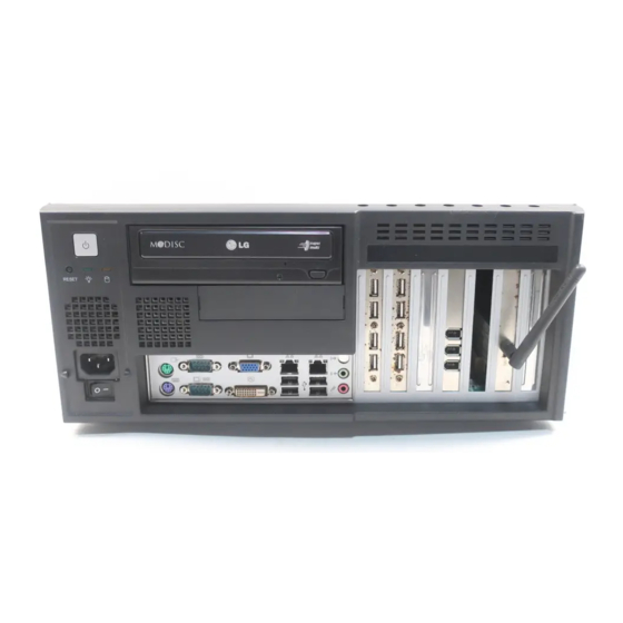
Front Access I/O Interface Design
Figure 2.10: Mounting Brace for Securing the Power Cord
Chapter 3 Operation
The Front Bezel of IPC-7120 (IPC-5120)
Figure 3.1: Front Bezel of IPC-7120
Figure 3.2: Front Bezel of IPC-5120
Switch and Button
LED Indicators
Table 3.1: LED Indicator Functions
Replacing the Cooling Fan
Replacing the 12 CM System Fan
Figure 3.3: Replacing the 12 CM Fan
Replacing the 4 CM Cooling Fan
Figure 3.4: Replacing the 4 CM Fan
Cleaning the Filter
Replacing the Power Supply
Figure 3.6: Removing the Front Bezel
Figure 3.7: Renoving the Power Supply
Figure 3.8: Replacing the Front Bezel
Appendix A Exploded Diagrams
Exploded Diagram of IPC-7120
Figure A.1: Exploded Diagram, IPC-7120
Exploded Diagram of IPC-5120
Figure A.2: Exploded Diagram, IPC-5120
Appendix B Motherboard Options
Appendix C Safety Instructions
English
C.1 English
German - Wichtige Sicherheishinweise
C.2 German – Wichtige Sicherheishinweise
Advertisement
Quick Links
1
Table 3.1: Led Indicator Functions
Download this manual
IPC-7120 / IPC-5120
Wallmount / Desktop Industrial
Chassis with Front I/O Interfaces
& Expansion Slots
User Manual
Table of
Contents
Previous
Page
Next
Page
1
2
3
4
5
Advertisement
Table of Contents
Need help?
Do you have a question about the IPC-7120 and is the answer not in the manual?
Ask a question
Questions and answers
Related Manuals for Advantech IPC-7120
Chassis Advantech IPC-7220 User Manual
Desktop/wall mountable ipc chassis (42 pages)
Chassis Advantech IPC-7132 User Manual
Cost-effective desktop / wallmount chassis for atx/micro atx motherboard and 10 slot backplane (30 pages)
Chassis Advantech IPC-623 User Manual
4u, 20-slot rackmount industrial chassis (52 pages)
Chassis Advantech IPC-616 User Manual
14-slot fault-resilient ipc chassis (22 pages)
Chassis Advantech IPC-603MB User Manual
Ultra compact 2u-high rackmount ipc chassis (30 pages)
Chassis Advantech IPC-610-H User Manual
4u rackmount chassis (26 pages)
Chassis Advantech IPC-6806S User Manual
Wallmount ipc chassis for 6 half-sized cards (40 pages)
Chassis Advantech IPC-602 Manual
Industrial e-server chassis (17 pages)
Chassis Advantech IPC-602 User Manual
2u 6-slot industrial rackmount chassis (36 pages)
Chassis Advantech IPC-613 User Manual
2u e-server chassis (16 pages)
Chassis Advantech IPC-6806 Manual
6-slot node ipc chassis (21 pages)
Chassis Advantech IPC-610F Manual
Industrial pc chassis (24 pages)
Chassis Advantech IPC-622MS Manual
Industrial pc chassis (18 pages)
Chassis Advantech IPC-6025 User Manual
5-slot desktop/wallmount chassis with scalability for multi-system solution (60 pages)
Chassis Advantech IPC-631 User Manual
Compact 4u front i/o rackmount chassis for atx/ microatx motherboard (34 pages)
Chassis Advantech IPC-3026 User Manual
Desktop / wallmount chassis for half-size sbc (30 pages)
This manual is also suitable for:
Ipc-5120
Table of Contents
Print
Rename the bookmark
Delete bookmark?
Delete from my manuals?
Login
Sign In
OR
Sign in with Facebook
Sign in with Google
Upload manual
Upload from disk
Upload from URL


Need help?
Do you have a question about the IPC-7120 and is the answer not in the manual?
Questions and answers