Table of Contents
Advertisement
Advertisement
Chapters
Table of Contents

Related Manuals for Vinten Vision 6


Summary of Contents for Vinten Vision 6
- Page 1 Contents Next Previous Page View Vision 6 Vinten Camera Control Solutions...
-
Page 2: Pan And Tilt Head
Vinten Broadcast Limited. Vinten, Vision and Quickfit are registered trademarks of Vinten Broadcast Limited. -
Page 3: Foreword
Particular attention must be paid to cleaning, especially after use in adverse conditions. To order spare parts or to obtain further information, application should be made to Vinten Broadcast Limited or to your local distributor. -
Page 4: Notes To Readers
Page Page View Notes to readers This is the on-line version of ‘Vision 6 Pan and Tilt Head Maintenance Manual’ (3449-9). Readers should be aware that the pagination differs between on-line and printed versions. Navigation Clicking the mouse on any blue text will move you around the document. -
Page 5: Safety - Read This First
Contents First Previous Next Previous Page Page Page View Safety - Read This First! Warning symbols in this maintenance manual Where there is a risk of personal injury, injury to others, or damage to the pan and tilt head or associated equipment, comments appear, highlighted by the word WARNING! and supported by the warning triangle symbol. -
Page 6: Table Of Contents
First Previous Next Previous Page Page Page View Contents Page Foreword ................3 Notes to readers . - Page 7 Fig 6.4 Vision 6 Pan and Tilt Head - Tilt Drag Unit Assembly......
-
Page 8: Abbreviations
Contents First Previous Next Previous Page Page Page View Abbreviations The following abbreviations are used in this publication: alternating current pound (weight) Amps Lubricated Friction across flats left hand as required MISO metric thread ASME American Society of Mech Engineers metre assy assembly... -
Page 9: Technical Specification
Contents First Previous Next Previous Page Page Page View Technical Specification Weight Head 2.3 kg (5.0 lb) Pan bar 0.2 kg (0.4 lb) Bowl clamp) 0.14 kg (0.3 lb) Height to mounting face 12.1 cm (4.76 in.) Length 12.9 cm (5.08 in.) Width 14.8 cm (5.83 in.) Load capacity... -
Page 10: Design Improvements
Contents First Previous Next Previous Page Page Page View Design Improvements SERIAL No. DETAILS INFORMATION Introduction of VHS pin as part of camera mounting plate 00150 Improved brake knobs 01126 Improved bowl clamp 01717 Changes to slide plate to better accommodate DV cameras 02215 Introduction of new pan bar 02636... -
Page 11: Description
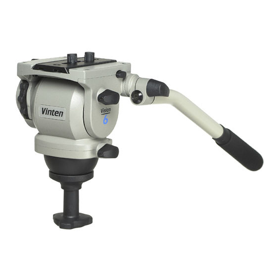
................3 Introduction The Vision 6 pan and tilt head is part of a range designed for broadcast professional, corporate and educational use. It is constructed largely in aluminium and magnesium alloys to produce a robust, lightweight unit. -
Page 12: Fig 1.1 Vision 6 Pan And Tilt Head
Contents First Previous Next Previous Page Page Page View (16) (15) (14) (13) (12) (11) (10) Fig 1.1 Vision 6 Pan and Tilt Head... - Page 13 Contents First Previous Next Previous Page Page Page View A ball base (13) and clamp for mounting on a 75 mm bowl is provided. A illuminated level bubble is fitted at the rear of the head. The bubble is illuminated by pressing the switch and extinguishes automatically after approximately 15 seconds.
- Page 14 1.1. Installing the head on a tripod The Vision 6 head is supplied with an integral 75 mm ball mount and is designed for installation on a compatible Vinten Vision tripod. To install the head, remove the bowl clamp assembly from the head, position the head on the tripod and refit the bowl clamp assembly from below.
-
Page 15: Mounting The Camera (Optional Quickfit Adaptor)
Contents First Previous Next Previous Page Page Page View Mounting the camera (optional Quickfit adaptor) To mount the camera using the optional Quickfit adaptor, proceed as follows (Fig 2.1): If not already attached, secure the Quickfit adaptor (18) to the slide plate (12) with the two screws provided (15). -
Page 16: Mounting The Camera (Optional Vhs Adaptor)
Contents First Previous Next Previous Page Page Page View Mounting the camera (optional VHS adaptor) The optional VHS adaptor (Fig 2.2) consists of a VHS pin and a 1/4 in. BSW camera mounting screw connected by a plastic link. To mount the camera using the VHS adaptor, proceed as follows: Remove the slide plate (12) from the head by releasing the slide clamp (6), pressing the slide... -
Page 17: Balancing The Head
Balancing the head Balancing the Vision 6 head achieves two objectives. Firstly, when a head is correctly balanced the operator will need a minimum amount of even effort to move the head. Secondly, once balanced, the head and its payload can be set to any tilt position and the head will maintain this position with “hands off”. -
Page 18: Pan And Tilt Brakes
DO NOT use the brakes to supplement drag. Pan and tilt drag Both the pan and tilt mechanisms incorporate the Vinten lubricated friction (LF) system to ensure smooth movement of the camera about these axes. and are fitted with control knobs to adjust the drag setting. - Page 19 Contents First Previous Next Previous Page Page Page View To increase drag, turn the knob clockwise, towards a higher graduation. To decrease drag, turn the knob anti-clockwise, towards a lower graduation. NOTE: Reduce drag to a minimum when the head is out of use for long periods.
-
Page 20: Special Tools
Special thumb screw 3441-907TL Assembling pan and tilt drag units NOTE: Adhesives and lubricants are not supplied by Vinten Broadcast Ltd and should be obtained under local arrangements Consumable materials Item Part No. Grease, Easyrun 50 Z150-081... -
Page 21: General
............20 General The Vision 6 pan and tilt head is robustly made to high engineering standards and little attention is required to maintain serviceability save regular cleaning. Attention to the following points will ensure a long and useful life with minimum need for repair. -
Page 22: Fig 4.1 Battery Replacement
Contents First Previous Next Previous Page Page Page View Battery replacement The level bubble is illuminated by pressing the switch. It remains lit for approximately 15 seconds. The battery should be replaced yearly or whenever the illumination is considered inadequate. WARNING!: If a payload is not fitted to the head, turn the balance knob full counter- clockwise to reduce the balancing force before tilting the head forwards. -
Page 23: Adjustments
Contents First Previous Next Previous Page Page Page View Adjustments Brake knob adjustment NOTE: The design of the pan and tilt brake knobs was improved at Serial No. 01126. The improved knobs, which are easier to remove and install, are interchangeable with the earlier knobs. The pan and tilt brake knobs are set during manufacture so that the brakes are fully applied before the knobs reach their upper stops. -
Page 24: Fig 4.2 Brake Knob Adjustment - Earlier Knobs
Contents First Previous Next Previous Page Page Page View 10.1 11.2 60° 10.2 11.3 15° 10.3 11.4 15° 11.1 11.5 Fig 4.2 Brake knob adjustment - earlier knobs... -
Page 25: Fig 4.3 Brake Knob Adjustment - Later Knobs
Contents First Previous Next Previous Page Page Page View 15.1 16.2 60° 15.2 16.3 15° 15.3 16.4 15° 16.1 16.5 Fig 4.3 Brake knob adjustment - later knobs... - Page 26 Contents First Previous Next Previous Page Page Page View To install the later knob (Fig 4.3): 16.1 Turn the shaft clockwise, by hand, until the brake is applied. 16.2 Turn the shaft 60° counter-clockwise. 16.3 Push the knob onto the shaft at the 15° position. 16.4 Turn the knob clockwise to the horizontal position and push it inwards.
-
Page 27: Fig 4.4 Drag Control Knob Adjustment
Contents First Previous Next Previous Page Page Page View Fig 4.4 Drag control knob adjustment... - Page 28 ..............22 General This section details procedures for disassembly and assembly of the Vision 6 pan and tilt head. Reference is made in the procedures to figures in Section 6 - Illustrated Parts List.
-
Page 29: Disassembly
Contents First Previous Next Previous Page Page Page View Disassembly Platform To remove the platform (Fig 6.2): NOTE: Do not remove the slide assembly (39) prior to removing the platform. This will retain the clamping and release components during removal. Remove four screws (3) securing platform (4) to tilt drag unit (6) and tilt brake unit (20). -
Page 30: Tilt Drag Unit
Remove the screw (24) and clamp washer (23) from the end of the pan shaft. NOTE: The pan drag unit assembly contains 12 cc of Vinten Fluid No. 3. Be prepared to catch any fluid that may leak from the assembly. -
Page 31: Tilt Brake Unit Assembly
(26). Remove two plugs (5) from the face of the tilt drag housing (6). NOTE: The tilt drag unit assembly contains 9 cc of Vinten Fluid No. 3. Be prepared to catch any fluid that may leak from the assembly. -
Page 32: Balance Mechanism
Contents First Previous Next Previous Page Page Page View Balance mechanism To remove the balance mechanism (Fig 6.2): 11.1 Remove the tilt drag unit assembly (Para 7) and the tilt brake unit assembly (Para 11.2 Remove screw (30) from actuator shaft (33). 11.3 Pull the bearing needle roller (13) out of the mechanism housing (8). -
Page 33: Assembly
Contents First Previous Next Previous Page Page Page View Assembly Electrical system To install the electrical system (Fig 6.6): 13.1 Position the PCB and wiring in the mechanism housing (4). 13.2 Push the battery connectors (10) onto the battery housing (3), observing correct polarity. Push the battery housing into the mechanism housing (4) 13.3 Position the LED (8) in its housing. -
Page 34: Tilt Brake Unit Assembly
Contents First Previous Next Previous Page Page Page View 14.10 Install the bearing needle roller (13) in the mechanism housing (8), ensuring roller engages in slot in adjustment slide. Secure pin with Silcoset. 14.11 Turn balance knob (8) fully counter-clockwise. NOTE: The balance spring is pre-loaded after the tilt brake and tilt drag assemblies are installed. -
Page 35: Pan Unit Assembly
17.14 Install the assembled tilt drag mechanism in the mechanism side cover (11). 17.15 Using a syringe through the plug holes (5), fill the bowl with 9 cc of Vinten Fluid No. 3. 17.16 Install two plugs (5). Wipe off any excess fluid. -
Page 36: Platform
(23) and the screw (24), using Loctite 222E. Tighten screw (24) down hard, loosen and then retighten to 1.695 Nm (15 lbf/in.). 19.16 Using a syringe through the plug holes (22), fill the bowl with 12 cc of Vinten Fluid No. 3. 19.17 Install two plugs (22). Wipe off any excess fluid. -
Page 37: Final Assembly
Contents First Previous Next Previous Page Page Page View To install the platform (Fig 6.2): 22.1 Position the platform on the head and secure with four screws (3) Final assembly To pre-load the balance spring (Fig 6.2): 23.1 Tighten screw (30) until it bottoms. 23.2 Install self-adhesive mechanism housing label (35). -
Page 38: Ordering Spare Parts
Fig 6.4 Vision 6 Pan and Tilt Head - Tilt Drag Unit Assembly...... -
Page 39: Main Assembly Part Numbers
Main assembly part numbers Ensure that the correct serial and part numbers are quoted when ordering main assemblies. Assembly Part No. Vision 6 pan and tilt head - main unit assembly 3449-11 Pan unit assembly 3449-12 Tilt drag unit assembly... -
Page 40: Fig 6.1 Vision 6 Pan And Tilt Head
Contents First Previous Next Previous Page Page Page View V6IP01 Fig 6.1 Vision 6 Pan and Tilt Head... - Page 41 Contents First Previous Next Previous Page Page Page View Fig 6.1 Vision 6 Pan and Tilt Head Item Part Nomenclature 3449-11 Main unit assembly (Fig 6.2, 6.3, 6.4, Fig 6.5 6.6) 3219-26 Pan bar unit assembly (Vision 5) (Fig 6.7)
-
Page 42: Fig 6.2 Vision 6 Pan And Tilt Head - Main Unit Assembly
Contents First Previous Next Previous Page Page Page View V6IP02 Fig 6.2 Vision 6 Pan and Tilt Head - Main Unit Assembly... - Page 43 Contents First Previous Next Previous Page Page Page View Fig 6.2 Vision 6 Pan and Tilt Head - Main Unit Assembly Item Part Nomenclature M004-103 Screw, countersunk head, pozidrive, M3 x 8 mm long 3431-338 Platform clamp knob M005-718 Screw, cap head, socket, M4 x 12 mm long...
- Page 44 Contents First Previous Next Previous Page Page Page View Fig 6.2 Vision 6 Pan and Tilt Head - Main Unit Assembly (Cont) Item Part Nomenclature 3325-337 Buffer M006-506 Screw, button head, socket, M5 x 16 mm long 3449-228 End washer...
-
Page 45: Fig 6.3 Vision 6 Pan And Tilt Head - Pan Unit Assembly
Contents First Previous Next Previous Page Page Page View V6IP03 Fig 6.3 Vision 6 Pan and Tilt Head - Pan Unit Assembly... - Page 46 Contents First Previous Next Previous Page Page Page View Fig 6.3 Vision 6 Pan and Tilt Head - Pan Unit Assembly Item Part Nomenclature 3441-22 Pan drag indicator assembly 3441-25 Pan drag knob assembly M004-813 Screw, grub, cup point, socket head, M3 x 10 mm long P900-012 Ball, steel, 6 mm dia.
-
Page 47: Fig 6.4 Vision 6 Pan And Tilt Head - Tilt Drag Unit Assembly
Contents First Previous Next Previous Page Page Page View V6IP04 Fig 6.4 Vision 6 Pan and Tilt Head - Tilt Drag Unit Assembly... - Page 48 Previous Next Previous Page Page Page View Fig 6.4 Vision 6 Pan and Tilt Head - Tilt Drag Unit Assembly Item Part Nomenclature 3449-904SP R.H. Side plate (spare) M004-813 Screw, grub, cup point, socket head, M3 x 10 mm long P900-012 Ball, steel, 6 mm dia.
-
Page 49: Fig 6.5 Vision 6 Pan And Tilt Head - Tilt Brake Unit Assembly
Contents First Previous Next Previous Page Page Page View V6IP05 Fig 6.5 Vision 6 Pan and Tilt Head - Tilt Brake Unit Assembly... - Page 50 Contents First Previous Next Previous Page Page Page View Fig 6.5 Vision 6 Pan and Tilt Head - Tilt Brake Unit Assembly Item Part Nomenclature M005-703 Screw, cap head, socket, M4 x 8 mm long 3449-211 Tilt brake disk P302-012...
-
Page 51: Fig 6.6 Vision 6 Pan And Tilt Head - Electrical Installation
Contents First Previous Next Previous Page Page Page View V6IP07 Fig 6.6 Vision 6 Pan and Tilt Head - Electrical Installation... - Page 52 Contents First Previous Next Previous Page Page Page View Fig 6.6 Vision 6 Pan and Tilt Head - Electrical Installation Item Part Nomenclature 3549-213 Battery cover C550-021 Battery, 12 Volts, MN21 or equivalent 3549-212 Battery housing 3449-201 Mechanism housing (Fig 6.2)
-
Page 53: Fig 6.7 Vision 6 Pan And Tilt Head - Pan Bars
Contents First Previous Next Previous Page Page Page View V6IP06 Fig 6.7 Vision 6 Pan and Tilt Head - Pan Bars... - Page 54 First Previous Next Previous Page Page Page View Fig 6.7 Vision 6 Pan and Tilt Head - Pan Bar Item Part Nomenclature NOTE: Pan bars 3219-26 and 3219-78 are interchangeable. 3219-78 was supplied from Serial No. 02636 onwards 3219-26 Pan bar unit assembly (Vision 5), comprising:...
- Page 55 Contents First Previous Next Previous Page Page Page View Fig 6.7 Vision 6 Pan and Tilt Head - Pan Bar Item Part Nomenclature 3219-239 Pan bar grip...
- Page 56 Contents First Previous Previous Page Page View...
- Page 57 Contents First Previous Next Previous Page Page Page View...
Need help?
Do you have a question about the Vision 6 and is the answer not in the manual?
Questions and answers