Table of Contents
Advertisement
Quick Links
Advertisement
Table of Contents

Related Manuals for Vinten Vision 6


Summary of Contents for Vinten Vision 6
- Page 1 Vision 6 Vinten Camera Control Solutions...
-
Page 2: Pan And Tilt Head
All rights reserved throughout the world. No part of this document may be stored in a retrieval system, transmitted, copied or reproduced in any way including, but not limited to, photocopy, photograph, magnetic or other record without the prior agreement and permission in writing of Vinten Broadcast Limited. Vinten, QuickFit and Vision are registered trademarks of Vinten Broadcast Limited. -
Page 3: Safety - Read This First
Limited, your local Vinten distributor (see back cover) or visit our website. For full details on maintenance and spare parts, please refer to the Vision 6 Pan and Tilt Head Maintenance Manual and Illustrated Parts List (Publication Part No. 3449-9) This is obtainable from Vinten Broadcast Limited or your local Vinten distributor. -
Page 4: Table Of Contents
Parts list..............17 Associated publication Vision 6 Pan and Tilt Head Maintenance Manual... - Page 5 Vision 6 (Left-Hand Side) Pan bar Balance knob Pan drag adjustment knob Illuminated level bubble Pan brake knob Pan bar mounting Tilt brake knob Slide lock release...
- Page 6 (15) (14) (10) (11) (13) (12) Vision 6 (Right-Hand Side) Slide plate (10) Slide plate clamp (11) Tilt drag adjustment knob (12) Switch for illuminated level bubble (13) Bowl clamp (14) Battery compartment (15) Camera mounting screws...
-
Page 7: Introduction
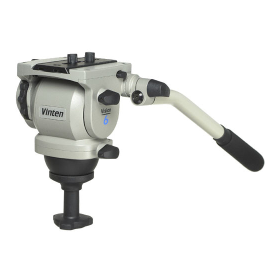
Introduction The Vision 6 pan and tilt head embodies an adjustable spring counterbalancing mechanism, LF drag assemblies for pan and tilt motions and an adjustable camera mounting plate. The balance system is easily adjusted by a knob on the rear of the head. Maximum and mini- mum payloads that can be balanced, and tilt ranges, are dependent on the weight of the camera and accessories and on the centre of gravity (C of G) height. - Page 8 Both the pan and tilt mechanisms incorporate the patented Vinten lubricated friction (LF) system to ensure smooth movement of the camera about these axes and are fitted with control knobs (3)(11) to adjust the drag setting. The whip-pan facility is unaffected by the pan drag setting.
-
Page 9: Operation
Operation Installing the head on a tripod The Vision 6 pan and tilt head is supplied with an integral 75 mm ball mount, designed for instal- lation on a compatible Vinten Vision tripod. Adaptors are available which enable the head to be installed on tripods or pedestals fitted with other mountings. - Page 10 Mounting the camera (VHS adaptor) The optional VHS adaptor (21) consists of a VHS pin and a 1/4 in. BSW camera mounting screw connected by a plastic link. To mount the camera using the VHS adaptor, proceed as follows: Remove the slide plate from the head by releasing the slide plate clamp (10), pressing the slide lock release and pulling the plate out to the rear.
- Page 11 Mounting the camera (optional Quickfit adaptor) If not already attached, secure the Quickfit Adaptor (18) to the slide plate with the two screws (15) provided. Free the Quickfit wedge (17) from the adaptor by simultaneously pushing in on the safety catch (20) and operating the wedge release (19).
-
Page 12: Balancing The Head
Balancing the head Balancing a Vision head achieves two objectives. Firstly, when a head is correctly balanced the operator will need a minimum amount of even effort to move the head. Secondly, once balanced, the head and its payload can be set to any tilt position and the head will maintain this position with ‘hands off’. - Page 13 (10) Balancing the head...
-
Page 14: Pan And Tilt Brakes
DO NOT use the brakes to supplement drag. Pan and tilt drag Both the pan and tilt mechanisms incorporate the Vinten LF system to ensure smooth movement of the camera about these axes and are fitted with control knobs to adjust the drag setting. -
Page 15: Servicing
Servicing Routine maintenance During use, check the following: Check the illumination of the level bubble. Replace battery if necessary. Check the effectiveness of the pan and tilt drag controls. Reset as necessary. Check the effectiveness of the pan and tilt brakes. Reset as necessary. No further routine maintenance is required. -
Page 16: Brake Knob And Drag Control Knob Adjustment
The pan and tilt brake and drag controls may require adjustment after prolonged use. These ad- justments should be carried out by competent persons as detailed in the Maintenance Manual. The Maintenance Manual may be obtained from Vinten Broadcast Limited or your local Vinten dis- tributor or from our website at www.vinten.com. -
Page 17: Parts List
Parts list The following lists include main assemblies, user-replaceable spare parts and optional accesso- ries. For further information regarding repair or spare parts, please contact Vinten Broadcast Ltd or your local distributor. For information on-line, visit our website at www.vinten.com.
Need help?
Do you have a question about the Vision 6 and is the answer not in the manual?
Questions and answers