Table of Contents
Advertisement
Quick Links
Download this manual
See also:
Operator's Manual
Advertisement
Table of Contents

Related Manuals for Vinten Protouch Pro-6HDV System


Summary of Contents for Vinten Protouch Pro-6HDV System
- Page 1 Contents Next Previous Page View Protouch Vinten Camera Control Solutions...
- Page 2 The Vitec Group plc. Vinten® is a registered trademark of The Vitec Group plc.
- Page 3 Particular attention must be paid to cleaning, especially after use in adverse conditions. To order spare parts or to obtain further information, application should be made to Vinten or to your local distributor, or visit our website at www.vinten.com.
-
Page 4: Notes To Readers
Contents First Previous Next Previous Page Page Page View Notes to readers This is the on-line version of ‘Protouch Pro-6 System Maintenance Manual’ (V4018-4990). Readers should be aware that the pagination differs between on-line and printed versions. Navigation Clicking the mouse on any blue text will move you around the document. -
Page 5: Safety - Read This First
(applicable in the European Union and European countries with separate collection systems). It shall be handed over to the applicable collection point for the recycling of electrical and electronic equipment. Please visit www.vinten.com/recycle for details. By ensuring this product is disposed of correctly, you will help prevent potentially negative consequences for the environment and human health, and help conserve natural resources. - Page 6 Contents First Previous Next Previous Page Page Page View Usage The Pro-6 System has been designed for television camera operators to support and balance a camera and ancillary equipment weighing up to 16 kg (13.2 lb). WARNING!: 1. Do NOT attempt to use this product if you do not understand how to operate it.
-
Page 7: Table Of Contents
First Previous Next Previous Page Page Page View Contents Page Foreword ................3 Notes to readers . - Page 8 Contents First Previous Next Previous Page Page Page View Illustrated Parts List Introduction ............... 45 Ordering spare parts .
- Page 9 Contents First Previous Next Previous Page Page Page View Abbreviations The following abbreviations are used in this publication: alternating current pound (weight) Lubricated Friction Amps across flats left hand as required MISO metric thread ASME American Society of Mech Engineers metre assy assembly...
-
Page 10: Technical Specification
Contents First Previous Next Previous Page Page Page View Technical Specification Pro-6 pan and tilt head Weight Head with bowl clamp ........... . .1.95 kg (4.29 lb) Pan bar. -
Page 11: Design Improvements
Contents First Previous Next Previous Page Page Page View Design Improvements SERIAL No. DETAILS INFORMATION Improvements to tripod bottom clamp adjuster Tripod 3819-03515... -
Page 12: Introduction And Description
Tripod spreaders ..............10 Introduction There are two Protouch Pro-6 systems from Vinten. Both systems comprise of a Pro-6 pan and tilt head, a Pozi-Loc two-stage tripod and a soft case. However, one system (Pro-6 HDVF) is supplied with an adjustable floor spreader and the other (Pro-6 HDVM) comes with an adjustable mid-level spreader. - Page 13 Contents First Previous Next Previous Page Page Page View (19) (18) (17) (16) (15) (14) (13) (12) (11) (10) Fig 1.1 Pro-6 Pan and Tilt Head Illuminated levelling bubble To enable the head to be levelled, an illuminated levelling bubble (11) is fitted to the rear of the head.
-
Page 14: Camera Mounting
Contents First Previous Next Previous Page Page Page View Camera mounting The camera is attached to the head by means of a slide plate (17), which is provided with a spring- loaded locating pin and 1/4 in. and 3/8 in. (19) screws. -
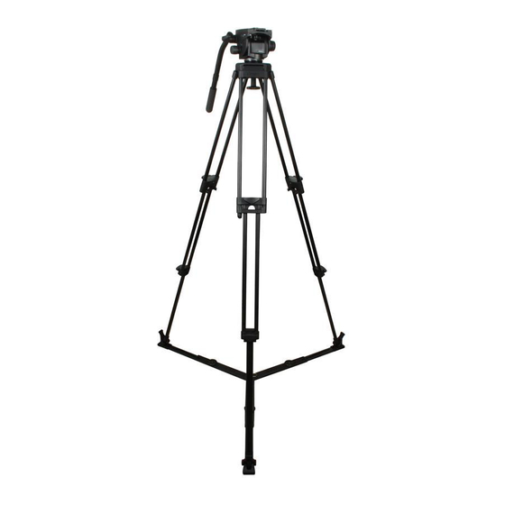
Page 15: Fig 1.2 Pozi-Loc Tripod And Floor Spreader
Contents First Previous Next Previous Page Page Page View (27) (20) (26) (21) (25) (24) (23) (22) Pozi-Loc Tripod and Floor Spreader Fig 1.2 Pro-6 HDVM system The Pro-6 HDVM system utilizes a mid-level spreader (Fig 1.3) which fastens to the attachment points (26). -
Page 16: Fig 1.3 Pozi-Loc Tripod And Mid-Level Spreader
Contents First Previous Next Previous Page Page Page View system to protect floors and carpets and prevents the tripod sinking into soft ground. The feet are secured to the tripod by rubber straps (33). NOTE: Always use the spreader where possible as this increases rigidity of the tripod. Adjustable extension clamps compensate for uneven ground. -
Page 17: Tripod And Floor Spreader
Contents First Previous Next Previous Page Page Page View Section 2 Operation Contents Para General................1 Assembly Tripod and floor spreader . - Page 18 Contents First Previous Next Previous Page Page Page View WARNING!: Stability is reduced when the tripod is fully extended with the floor spreader in the closed position. Use with care. Tripod and mid-level spreader To install the mid-level spreader (Fig 1.3): Grip the ends of each spreader arm in turn between thumb and fore-finger and press in both attachment release buttons (30).
-
Page 19: Pan And Tilt Head
Contents First Previous Next Previous Page Page Page View In adverse conditions secure the tripod using the tie-down hook (27), or suspend a weight from the hook. WARNING!: Stability is reduced when the tripod is fully extended with the floor spreader in the closed position. -
Page 20: Checking Camera Balance
Contents First Previous Next Previous Page Page Page View Fig 2.1 Mounting the camera Checking camera balance The Pro-6 head provides a selectable balance range, set for payloads of 2.5kg (5.5lb) to 6kg (13.2lb) at a centre of gravity (C of G) height of 5.5cm (2.2in.). The graph (Fig 2.2) shows the relationship between C of G height and payload for optimum performance. -
Page 21: Pan And Tilt Brakes
Contents First Previous Next Previous Page Page Page View Fig 2.2 Balance graph Pan and tilt brakes Brakes on each axis allow the head to be locked at any chosen position. The operating lever for the pan brake (15) is at the rear of the head. The tilt brake is operated by a lever on the left-hand side of the head. -
Page 22: Pan And Tilt Drag
Contents First Previous Next Previous Page Page Page View Pan and tilt drag Both the pan and tilt mechanisms incorporate a fluid drag system to ensure smooth movement of the camera about these axes. The tilt drag adjustment knob is on the left -hand side of the head, the pan drag knob (14) is on the top of the body, beneath the platform. -
Page 23: Fig 2.3 Carrying Strap Installation
Contents First Previous Next Previous Page Page Page View (34.1) (34.2) (34.3) (34.4) (25.1) (34.5) (34.6) (20.1) (20.2) (34.1) (34) (20) Fig 2.3 Carrying strap installation Dollies The Pro-6 system may be mounted on a variety of OB and studio dollies as follows: PD114 dolly. -
Page 24: Special Tools
Shell Darina R2 grease (yellow) General lubrication Arexon TT163 General lubrication Optalus A0 140 Pan and tilt friction Chesterton 622 Tripod clamps Loctite 221 (Vinten Part No. Z002-026) Screw locking WARNING!: Always follow the recommended handling instructions supplied with each consumable material product. -
Page 25: Routine Maintenance
Contents First Previous Next Previous Page Page Page View Section 4 Servicing Contents Para General................1 Cleaning . -
Page 26: Battery Replacement
Contents First Previous Next Previous Page Page Page View Check for ageing and cracking of the rubber foot securing straps on the spreader and renew if necessary. No further routine maintenance is required. Battery replacement The battery illuminates the level bubble (11) when the switch (13) -
Page 27: Pan Brake Knob Adjustment
Contents First Previous Next Previous Page Page Page View Adjustments Pan brake knob adjustment Because its movement is restricted, the pan brake knob (15) may require adjustment after prolonged use. To adjust the pan brake knob: 10.1 Remove the securing screw (15.1) and pull the knob (15) -
Page 28: Tilt Brake Knob Adjustment
Contents First Previous Next Previous Page Page Page View Tilt brake knob adjustment Because its movement is restricted, the tilt drag knob may also require adjustment after prolonged use: To adjust the tilt brake knob: 12.1 Slide off the rubber tilt drag knob as shown in (Fig 4.2). -
Page 29: Fig 4.3 Top Clamp Adjustment
Contents First Previous Next Previous Page Page Page View 14.3 While sliding the leg in and out, gradually tighten the threaded insert (21.2) until the clamp begins to grip. 14.4 If not aligned, back off the threaded insert (21.2) until a slot aligns with the hole for screw (21.1). 14.5 Back off the threaded insert (21.2) a further three slots... -
Page 30: Fig 4.4 Bottom Clamp Adjustment
Contents First Previous Next Previous Page Page Page View (21.3) (21) (21.4) (21.5) POSITION 1 (21.6) (21) Fig 4.4 Bottom clamp adjustment... -
Page 31: Pro-6Hdv Pan And Tilt Head
Contents First Previous Next Previous Page Page Page View Section 5 Repair Contents Para General................1 Pro-6HDV pan and tilt head Disassembly Platform. - Page 32 Contents First Previous Next Previous Page Page Page View General This section details procedures for disassembly and assembly of the Pro-6 pan and tilt head, Pozi- Loc tripod and Pro-6 mid-level spreader. Reference is made in the procedures to figures in Section 6 - Illustrated Parts List.
- Page 33 Contents First Previous Next Previous Page Page Page View Remove the two balance selector pins (1.12) and retain the two springs (1.10). Centre cover Remove the centre cover as follows (Fig 6.2): Carefully prise off the self-adhesive pan drag knob label (4.1). Remove the nut (4.2) and pull the pan drag knob (4.5), washer (4.4) and bearing (4.3) off the pan drag adjustment assembly (6).
- Page 34 Contents First Previous Next Previous Page Page Page View 10.1 Remove two screws (3.1) securing the tilt drag adjuster arm (1) to the adjustable drag disc (3.5). 10.2 Carefully prise off the tilt drag knob boot (6.3). 10.3 Remove the tilt drag grub screw (6.1) and unscrew the tilt drag knob (6.2) and retain the washer (4.5).
- Page 35 Contents First Previous Next Previous Page Page Page View Assembly Lubrication During assembly, lubricate components as follows: 13.1 Shell Darina R2 (yellow) grease 13.1.1 The small threaded part of the shaft of the pan base assembly (Fig 6.4 Item 5.2). 13.1.2 The balance selection pins (Fig 6.3...
- Page 36 Contents First Previous Next Previous Page Page Page View 14.3 Install the illumination PCB (9.3) into the support plate (9.2) ensuring that the plastic retaining tabs secure the PCB. 14.4 Install the battery (9.4) into the holder on the PCB, ensuring the correct polarity (Fig 6.2).
- Page 37 Contents First Previous Next Previous Page Page Page View 15.14 Turn the tilt brake lever (5.5) fully clockwise and ensure that the brake is released. Turn the lever (5.5) counterclockwise and ensure the brake is applied at a suitable position before the lever (5.5) interferes with other head controls.
- Page 38 (Fig 6.2): 18.1 Position the centre cover (5) on the centre housing (8.2), with the Vinten Protouch logo facing forwards and push down to engage the lugs. 18.2 Install the pan drag knob (4.5), washer (4.4) and bearing (4.3) onto the protruding pan base thread (Fig 6.4...
-
Page 39: Replacing Tripod Legs
Contents First Previous Next Previous Page Page Page View 20.6 Install the balance knob (1.4), secure with screw (1.3) and fit balance knob bung (1.2). 20.7 If necessary lubricate the tilt bearing sleeve (1.11) with AGIP PV grease and install into the right- hand side plate (1.9). -
Page 40: Replacing The Components Of The Top Clamp Assembly
Contents First Previous Next Previous Page Page Page View Installation Install the tripod leg as follows (Fig 6.7): 26.1 Install two leg pivot friction rings (7) and two leg pivot washers (8) on the tripod leg, oriented as noted in removal NOTE: Do not apply any lubricant to the bowl, the leg trunnions, leg pivot friction rings or washers. -
Page 41: Replacing The Components Of The Bottom Clamp Assembly
Contents First Previous Next Previous Page Page Page View Replacing the components of the bottom clamp assembly To dismantle the bottom clamp it is necessary to remove the oval leg. NOTE: The design of the bottom clamp has been modified At Serial No. - Page 42 Contents First Previous Next Previous Page Page Page View 35.1 Position the clamp knob (23) on the bottom clamp shaft (18) and turn the knob counterclockwise to the ‘OFF’ position 35.2 Install the grubscrew (16) in the bottom clamp shaft (18). Adjust the clamp (See ‘Pozi-Loc’...
-
Page 43: Leg Assembly
Contents First Previous Next Previous Page Page Page View 42.1 Position the clamp knob (23) on the bottom clamp shaft (29) and turn the knob counterclockwise to the ‘OFF’ position 42.2 Install a grubscrew (30) in the bottom clamp shaft (29). 42.3 Adjust the clamp (See ‘Pozi-Loc’... - Page 44 Contents First Previous Next Previous Page Page Page View Assemble and refit the leg assembly as follows (Fig 6.9): 45.1 Refit the two pivot blocks (12) on the swivel feature on the end of the leg sub assembly (10), and secure using two screws (17) and two nuts (11).
-
Page 45: Ordering Spare Parts
Contents First Previous Next Previous Page Page Page View Section 6 Illustrated Parts List Contents Para Introduction ................1 Ordering spare parts. -
Page 46: Main Assembly Part Numbers
Contents First Previous Next Previous Page Page Page View Main assembly part numbers Ensure that the correct serial and part numbers are quoted when ordering main assemblies. Assembly Part No. Pro-6 pan and tilt head, comprising: V4018-0001 Pro-6 pan and tilt head - main unit assembly V4018-1000 Pan bar assembly PRO6LV... - Page 47 Contents First Previous Next Previous Page Page Page View Fig 6.1 Pro-6 Systems...
-
Page 48: Fig 6.1 Pro
Contents First Previous Next Previous Page Page Page View Fig 6.1 Pro-6 Systems Item Part Nomenclature V4018-0001 Pro-6 pan and tilt head (Fig 6.2) (Fig 6.3) (Fig 6.4) (Fig 6.5) 3819-3 Pozi-Loc two-stage tripod (Fig 6.6) 3818-3 Floor spreader (Fig 6.8), supplied with Pro-6 HDVF system V4032-0001 Mid-level spreader... - Page 49 Contents First Previous Next Previous Page Page Page View Fig 6.2 Pro-6 Pan and Tilt Head - Main Casting and Platform...
-
Page 50: Pan And Tilt Head - Main Casting And Platform
Contents First Previous Next Previous Page Page Page View Fig 6.2 Pro-6 Pan and Tilt Head - Main Casting and Platform Item Part Nomenclature PRO6PLV Camera plate for Pro-6 Screw, camera mounting, 1/4 in. BSW Screw, camera mounting, 3/8 in. BSW Slide plate Plug, camera screw blanking RV4018-2004... - Page 51 Contents First Previous Next Previous Page Page Page View Fig 6.2 Pro-6 Pan and Tilt Head - Main Casting and Platform (Cont) Item Part Nomenclature R503,90 Assembly, small pan bearing Nut, M10, nyloc, thin Bearing, ball, thrust Washer, M10, plain, heavy R503,310 Assembly, centre housing Sleeve, tilt bearing...
- Page 52 Contents First Previous Next Previous Page Page Page View 1.10 1.11 1.12 Fig 6.3 Pro-6 Pan and Tilt Head - RH Side Plate and Balance Assembly...
- Page 53 Contents First Previous Next Previous Page Page Page View Fig 6.3 Pro-6 Pan and Tilt Head - RH Side Plate and Balance Assembly Item Part Nomenclature RV4018-2002 Assembly, right hand side housing RV4018-2012 Assembly, balance knob Plug, balance knob Screw, countersunk, socket, M4 x 8 mm long Balance knob Needle roller Cam, balance selection...
- Page 54 Contents First Previous Next Previous Page Page Page View Fig 6.4 Pro-6 Pan and Tilt Head - Pan Drag and Ball Base...
-
Page 55: Fig 6.4 Pro
Contents First Previous Next Previous Page Page Page View Fig 6.4 Pro-6 Pan and Tilt Head - Pan Drag and Ball Base Item Part Nomenclature R503,310 Assembly, centre housing Sleeve, tilt bearing Assembly, centre housing mechanism Spring clip, level bubble Level bubble Sleeve, tilt brake Sleeve, pan bearing... - Page 56 Contents First Previous Next Previous Page Page Page View Fig 6.5 Pro-6 Pan and Tilt Head - LH Side Plate and Tilt Brake...
- Page 57 Contents First Previous Next Previous Page Page Page View Fig 6.5 Pro-6 Pan and Tilt Head - LH Side Plate and Tilt Brake Item Part Nomenclature R501,60 Arm, tilt drag adjustment R503,310 Assembly, centre housing Spring clip, level bubble Level bubble Sleeve, tilt bearing Assembly, centre housing mechanism, consisting of: Centre housing mechanism...
- Page 58 Contents First Previous Next Previous Page Page Page View Fig 6.5 Pro-6 Pan and Tilt Head - LH Side Plate and Tilt (Cont)Brake Item Part Nomenclature Grub screw, dog point, M 4 x 10 mm long RV4018-2017 Assembly, tilt drag knob Grub screw, M 4 x 8mm long Knob, tilt drag Boot, tilt drag knob...
- Page 59 Contents First Previous Next Previous Page Page Page View Fig 6.6 Pozi-Loc Two-Stage Tripod (3819-3)
- Page 60 Contents First Previous Next Previous Page Page Page View Fig 6.6 Pozi-Loc Two-Stage Tripod (3819-3) Item Part Nomenclature 3774-15 Bowl assembly (75mm) 3498-322 Hook 3819-11 Leg assembly (Fig 6.7) 3310-12 Strap assembly...
- Page 61 Contents First Previous Next Previous Page Page Page View Earlier tripods - two M5 grubscrews 3770_3_IP Fig 6.7 Leg Assembly (3819-11)
- Page 62 Contents First Previous Next Previous Page Page Page View Fig 6.7 Leg Assembly (3819-11) Item Part Item 3774-15 Bowl assembly (75mm) 3498-321 Leg Pivot Clamp 3498-338 Spherical Washer M007-506 Screw, button head, socket, M6 x 20 mm long J550-112 Cap, tube, dome type, to fit over 3.2 mm diameter 3498-322 Hook 3498-226...
- Page 63 Contents First Previous Next Previous Page Page Page View Fig 6.7 Leg Assembly (3819-11) (Cont) Item Part Item NOTE: The design of the bottom clamp has been modified At Serial No. 03515, the shaft was fitted with a locking thread insert and the 2 x M5 grubscrews, were changed to 1 x M5 x 10 mm Earlier tripods - two M5 grubscrews 3770-213...
- Page 64 Contents First Previous Next Previous Page Page Page View Fig 6.8 Floor Spreader (3818-3)
- Page 65 Contents First Previous Next Previous Page Page Page View Fig 6.8 Floor Spreader (3818-3) Item Part Nomenclature 3313-219 Split ring 3363-201 Centre moulding 3313-211 Hinge pin M701-054 'E'-Clip, crescent ring (“e”-clip variation), 4 mm shaft dia. x 0.40 mm thick 3363-202 Leg moulding inner (female) 3313-214...
-
Page 66: Parts Diagram
Contents First Previous Next Previous Page Page Page View Fig 6.9 Mid-level Spreader (V4032-0001) - Page 67 Contents First Previous Next Previous Page Page Page View Fig 6.9 Mid-level Spreader (V4032-0001) Item Part Nomenclature M703-001 Key ring V4032-2003 Label, selector cap M101-013 Screw, self tapping, c’sk head, pozi, M 3.5 x 12 mm long V4032-2002 Retaining disc J532-067 Spring, compression, 3.5 mm OD, 2.71 mm ID x 25 mm long P900-008...
Need help?
Do you have a question about the Protouch Pro-6HDV System and is the answer not in the manual?
Questions and answers