Symbol WS 2000 System Installation Manual
Hide thumbs
Also See for WS 2000:
- System reference manual (494 pages) ,
- Quick installation manual (48 pages) ,
- Configuration and deployment manual (15 pages)

Related Manuals for Symbol WS 2000


Summary of Contents for Symbol WS 2000
- Page 1 Branch Office Wireless Networking Symbol Wireless Switch WS 2000 Solution (802.11 a+b/g) System Installation Guide...
- Page 2 © 2004 Symbol Technologies, Inc. All rights reserved. No part of this publication can be modified or adapted in any way, for any purposes without permission in writing from Symbol Technologies (Symbol). The material in this manual is subject to change without notice. Symbol reserves the right to make changes to any product to improve reliability, function, or design.
- Page 3 The following icon conventions are used throughout this document. Indicates tips, hints, and special requirements. Care is required. Disregarding cautions can cause data loss or equipment damage. Indicates a potentially dangerous condition or procedure that only Symbol-trained personnel should attempt to correct or perform.
-
Page 4: Table Of Contents
Installing the WS 2000 Wireless Switch ....... . . 16... - Page 5 Configuring the WS 2000 Wireless Switch 27 Getting Started with the WS 2000 Wireless Switch ......27 Step 1: Setting up Administrative Communication to the Switch .
-
Page 6: To The Installer
This guide is intended to assist the technician responsible for installing a wireless system (both a WS 2000 Wireless Switch and a AP 300 802.11a/b/g Access Port) in a facility. It assumes that the technician is familiar with basic Ethernet LAN-based networking concepts. This guide provides specifications, procedures, and guidelines to use during the installation process. -
Page 7: Verifying Package Contents
To the Installer 1.1 Verifying Package Contents Inspect the package contents and report any missing or damaged items to your sales representative. The Symbol Branch Office Wireless Switch Solution packages should contain the following: WS 2000 Related Parts AP 300 Related Parts •... -
Page 8: Symbol Branch Office Wireless Switch Solution
Wireless Switch Solution 2.1 Introduction The Symbol Branch Office Wireless Switch Solution provides both a complete wireless for the enterprise branch office and small-medium businesses. The WS 2000 Wireless Switch can connect directly to a cable or DSL modem, and can also connect to other wide-area networks through a Layer 2 or 3 device (such as a switch or router).The AP 300 Access Port links wireless... -
Page 9: Ws 2000 Wireless Switch Description
The WS 2000 offers the power and cost-efficiencies of second-generation wireless networking. Intelligence previously distributed and duplicated throughout first-generation access point-based wireless LANs is centralized and aggregated in the WS 2000 Wireless Switch, delivering unprecedented power and control, and reduced deployment and management costs. - Page 10 WS 2000 System Installation Guide 2.2.1 WS 2000 Technical Specifications Physical Specifications Width 286 mm (11.26 in.) Height 45 mm (1.75 in.) Depth 203 mm (7.99 in.) Weight 0.64 kg Power Specifications Max Power Consumption 90-256VAC, 47-63 Hz, 3A Operating Voltage...
-
Page 11: Ap 300 Access Port Description
(PoE) power source. It can receive all power and transfer data through the same CAT-5 cable. No additional power supply is required. The Symbol Branch Office Wireless Switch Solution provides two placement options: wall and ceiling. Wall mount slots fit onto two screws. Arrows on the case guide placement of the screws. -
Page 12: Led Indicators
WS 2000 System Installation Guide 2.3.1 AP 300 Access Port Radio Characteristics The Symbol Branch Office Wireless Switch Solution is an IEEE 802.11-compliant device containing two 802.11 radios: an 802.11g radio operating in the 2.4 to 2.5 GHz band and an 802.11a radio operating in the 4.9 to 5.875 GHz band. -
Page 13: Other Specifications
Symbol Branch Office Wireless Switch Solu- 2.3.2.1 AP 300 Access Port Technical Specifications Physical Specifications Length 241 mm (9.5 in.) Width 178 mm (7.0 in.) Height 51 mm (2.0 in.) Weight 0.45 kg (1.0 lb.) Power Specifications Operating Voltage 48VDC typical; 36-57VDC range... -
Page 14: Installing The Branch Office Wireless System Solution
Wireless System Solution 3.1 The Installation Process The Symbol Branch Office Wireless Switch Solution can operate in various locations, allowing placement in most environments. The basic installation steps are: 1. Select a site (desk, wall, or rack) for installation of the wireless switch. -
Page 15: Warnings
Port. 6. Plug in WAN and LAN (Access Port) connections to the switch and turn on switch. 7. See Chapter 4, Configuring the WS 2000 Wireless Switch for information on how to configure the switch for your network and devices. -
Page 16: Installing The Ws 2000 Wireless Switch
3.3 Installing the WS 2000 Wireless Switch 3.3.1 Selecting a Site for Installation The WS 2000 Wireless Switch can be installed on a flat surface, on a wall, or in a rack. In selecting a site, the installer should verify that the location has access to: •... - Page 17 Installing the Branch Office Wireless System 3. Remove the backings from the four (4) rubber feet and stick them to the switch on the four circles, as shown. The feet will be right next to the four plugs. Power Plug Connector Rubber Plugs 4.
- Page 18 WS 2000 System Installation Guide Align the RJ-45 ports on the switch with the embossed port symbols on the front of the wall mount bracket. Wall Embossed Port Symbols 3. Connect the power supply to the switch, but not to the wall outlet.
-
Page 19: Rack Mounting
Installing the Branch Office Wireless System The wall mount bracket is designed to allow threading of cables underneath the bracket. There is space underneath the wall mount bracket to hold cables. Cables can be placed above, between, or below the attachment points. 3.3.4 Rack Mounting The rack mounting option provides a 1U bracket to the switch allowing it to be mounted in a standard rack. - Page 20 3.3.5 Securing the Network Switch The WS 2000 Wireless Switch comes with a lock port that is compatible with most locking systems. The lock port is on the rear of the switch, opposite the power connector. In order to have clear access,...
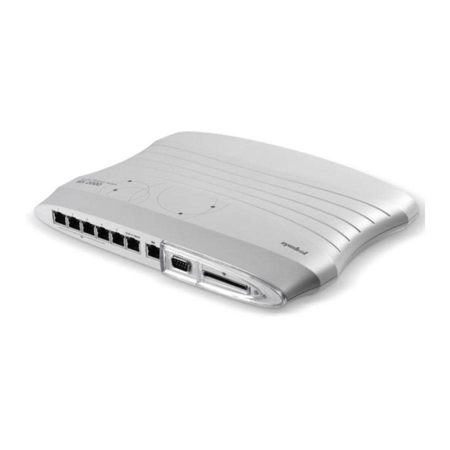
- Page 21 Power LED (PoE) The WS 2000 Wireless Switch provides six LAN ports and one WAN port. LAN Ports 1-4 provide 802.3af PoE support. Connect the Ethernet cable that will go into the Access Port into one of these four LAN ports.
-
Page 22: Installing The Ap 300 Access Port
WS 2000 System Installation Guide The WAN port is capable of hooking up to a DSL or cable modem, or to any Layer 2/3 network device. Plug devices into RJ-45 ports using standard CAT-5 patch cables. The power LED flashes during startup and remains lit during normal operation. - Page 23 Installing the Branch Office Wireless System 2. Connect a CAT-5 cable to a compatible 802.3af power source and run the cable to the installation site. Ensure that there is sufficient slack on the cable to perform the installation steps. 3.4.1 Wall Mounting Wall mounting requires hanging the AP 300 Access Port along its width or length using the pair of slots on the bottom of the unit.
- Page 24 WS 2000 System Installation Guide 2. Using the arrows on one edge of the case as guides, move the edge to the midline of the mounting area and mark points on the midline for the screws. 3. At each point, drill a hole in the wall, insert an anchor, screw into the anchor the wall mounting screw and stop when there is 1mm between the screw head and the wall.
- Page 25 Installing the Branch Office Wireless System 3.4.2.2 Ceiling Mount Procedure 1. If required, loop a safety wire—with a diameter of at least 1.01 cm (.04 in.), but no more than 0.158 cm (.0625 in.) —through the tie post and secure the loop. 2.
- Page 26 WS 2000 System Installation Guide 3.4.3 Lock Port The lock port, compatible with laptop-style security cables, is on the side of the case.
-
Page 27: Configuring The Ws 2000 Wireless Switch
WS 2000 Wireless Switch Getting Started with the WS 2000 Wireless Switch This section provides just enough instruction to set up the WS 2000 Wireless Switch, connect an Access Port, and test communications with a single mobile unit and the wide area network (WAN). -
Page 28: Step 1: Setting Up Administrative Communication To The Switch
For optimum compatibility use Sun Microsystems’ JRE 1.4 or higher (available from Sun’s website), and be sure to disable Microsoft’s Java Virtual Machine if it is installed. The following screen is displayed. 4. Log in using “admin” as the User ID and “symbol” as the Password. - Page 29 Configuring the WS 2000 Wireless Switch 5. If the login is successful, the following dialog window is displayed. Enter a new admin password in both fields, and click the Update Password Now button. Once the admin password has been updated, the System Settings screen is displayed.
-
Page 30: Step 2: Setting The Basic Switch Settings
Step 3: Configuring the LAN Interface The first step of network configuration process is to figure out the topology of the LAN. The WS 2000 Wireless Switch allows the administrator to enable and configure four different subnets. The administrator can assign an IP address, port associations, DHCP settings, and security settings to each subnet. -
Page 31: Enable Subnet1
(such as the subnet configuration screens) where the administrator can set the data. Network Network (subnet) name is a descriptive string that should describe the subnet’s function. The WS 2000 Network Management System uses subnet names throughout the configurations screens. -
Page 32: Step 4: Configuring Subnet1
The Interfaces field also lists the WLANs that are associated with the subnet. Step 4: Configuring Subnet1 The WS 2000 Network Management System allows the administrator to define and refine the configuration of the enabled subnets. Each of four subnets (short for “subnetworks”) can be configured as an identifiably separate part of the switch-managed local area network (LAN). - Page 33 Configuring the WS 2000 Wireless Switch 2. Check to make sure that all the ports and WLAN1 are selected for this subnet. WLAN1 should automatically be included if the switch and the access port are communicating properly. If WLAN1 is not present in the list, check: •...
-
Page 34: Step 5: Configuring The Wan Interface
WAN port might connect to a DSL or cable modem to access the Internet. The WS 2000 Wireless Switch includes one WAN port. In order to set up communications with the outside world, select Network Configuration --> WAN from the left menu. The following WAN configuration page appears. - Page 35 Client is checked, the switch is limited to one WAN IP address. This choice is required when: • The host router or switch on the WAN is communicating with the WS 2000 Wireless Switch using DHCP. • The switch is interfacing with an Internet Service Provider (ISP) that uses DHCP addressing.
-
Page 36: Step 6: Enabling Wireless Lans (Wlans)
Step 6: Enabling Wireless LANs (WLANs) The WS 2000 Wireless Switch works either in a wired or wireless environment; however, the power of the switch is associated with its support of wireless networks. In order to use the wireless features... -
Page 37: Wireless Summary Area
Configuring the WS 2000 Wireless Switch To start the WLAN configuration process, select the Network Configuration --> Wireless item from the left menu. The following Wireless summary screen appears. Wireless Summary Area The top portion of the window displays a summary of the WLANs that are currently defined. This is the screen in which the administrator can enable or disable a WLAN. -
Page 38: Step 7: Configuring Wlan Security
WS 2000 System Installation Guide Use the Access Port Adoption area to assign Access Ports to a particular WLAN. The switch can adopt up to six Access Ports at a time, but the list of allowed Access-Port addresses (displayed in this area) can exceed six in number. -
Page 39: Setting The Authentication Method
Setting the Authentication Method The authentication method sets a challenge-response procedure for validating user credentials such as username, password, and sometimes secret-key information. The WS 2000 Wireless Switch provides two methods for authenticating users: 802.1x EAP and Kerberos. The administrator can select between these two methods. -
Page 40: Step 8: Testing Connectivity
WS 2000 System Installation Guide encryption of wireless data. However, networks that require more security are at risk from a WEP flaw. An unauthorized person with a sniffing tool can monitor a network for less than a day and decode its encrypted messages. -
Page 41: Where To Go From Here
WEP settings on the mobile device. 4. In the Web browser, enter a URL for a site (such as www.symbol.com) on the WAN. If the site does not appear, go to the WAN Stats screen (Status & Statistics --> WAN Stats) to review the status of the WAN connection. -
Page 42: Regulatory Information
Regulatory Information All Symbol devices are designed to be compliant with rules and regulations in locations they are sold and will be labeled as required. Any changes or modifications to Symbol Technologies equipment, not expressly approved by Symbol Technologies, could void the user’s authority to operate the equipment. -
Page 43: Power Supply
Configuring the WS 2000 Wireless Switch The use of 5 GHz RLANs has varying restrictions of use; please refer to the Symbol Declaration of Conformity (DoC) for details. Operation of the AP 300 Access Port without regulatory approval is illegal. -
Page 44: Statement Of Compliance
Belgium, outside usage is restricted to 2.460–2.4835 GHz • Italy requires a user license for outside usage. The use of 5 GHz RLANs has varying restrictions for use within the EEA; please refer to the Symbol Declaration of Conformity (DoC) for details at http://www2.symbol.com/doc/. Power Supply Use only a Symbol-approved power supply output rated 48VDC. -
Page 45: Service And Support
Before using the unit, it must be configured to operate in the facility’s network and run your applications. If you have a problem running your unit or using your equipment, contact your facility’s Technical or Systems Support. If there is a problem with the equipment, they will contact the Symbol Support Center: United States... -
Page 46: Customer Support
Customer Support specialists cannot solve a problem, access to all technical disciplines within Symbol becomes available for further assistance and support. Symbol Customer Support responds to calls by e-mail, telephone or fax within the time limits set forth individual contractual agreements. - Page 47 Symbol Developer Program http://devzone.symbol.com/ Symbol Knowledge Base http://kb.symbol.com/register.asp For warranty and service information, contact the Symbol Support Center: telephone 1-631-738-6213 or 1-800-653-5350; fax: (631) 563-5410; or E-mail: support@symbol.com. Obtain additional information by contacting Symbol at: • 1-800-722-6234, inside North America •...
- Page 48 WS 2000 System Installation Guide...
- Page 49 Configuring the WS 2000 Wireless Switch...
- Page 50 Symbol Technologies, Inc. One Symbol Plaza Holtsville, New York 11742-1300 http://www.symbol.com 72-70601-01 Document Revision A October 2004...
Need help?
Do you have a question about the WS 2000 and is the answer not in the manual?
Questions and answers