Symbol WS 2000 Quick Installation Manual
Hide thumbs
Also See for WS 2000:
- System reference manual (494 pages) ,
- System installation manual (50 pages) ,
- Configuration and deployment manual (15 pages)

Related Manuals for Symbol WS 2000


Summary of Contents for Symbol WS 2000
- Page 1 Branch Office Wireless Networking Symbol Wireless Switch WS 2000 Solution (802.11 b) Quick Installation Guide...
- Page 2 © 2004 Symbol Technologies, Inc. All rights reserved. No part of this publication can be modified or adapted in any way, for any purposes without permission in writing from Symbol Technologies (Symbol). The material in this manual is subject to change without notice. Symbol reserves the right to make changes to any product to improve reliability, function, or design.
- Page 3 The following icon conventions are used throughout this document. Indicates tips, hints, and special requirements. Care is required. Disregarding cautions can cause data loss or equipment damage. Indicates a potentially dangerous condition or procedure that only Symbol-trained personnel should attempt to correct or perform.
-
Page 4: Table Of Contents
Installing the WS 2000 Wireless Switch ....... . . 15... - Page 5 Configuring the WS 2000 Wireless Switch 27 Getting Started with the WS 2000 Wireless Switch......27 Step 1: Setting up Administrative Communication to the Switch .
-
Page 6: To The Installer
To the Installer This guide is intended to assist the technician responsible for installing the WS 2000 Wireless Switch and the AP 100 802.11b Access Port and get the system to a known working configuration. It assumes that the technician is familiar with basic Ethernet LAN-based networking concepts. -
Page 7: Verifying Package Contents
Inspect the package contents and report any missing or damaged items to a sales representative. This system ships in a large box containing two smaller boxes, one for the WS 2000 Wireless Switch and one for the AP 100 Access Port. These packages should contain the following:... -
Page 8: Symbol Branch Office Wireless Switch Solution
The Branch Office Wireless Switch Solution provides both a complete wireless for the enterprise branch office and small-medium businesses. The WS 2000 Wireless Switch can connect directly to a cable or DSL modem, and can also connect to other wide-area networks through a Layer 2 or 3 device (such as a switch or router). -
Page 9: Ws 2000 Wireless Switch Description
The WS 2000 offers the power and cost-efficiencies of second-generation wireless networking. Intelligence previously distributed and duplicated throughout first-generation access point-based wireless LANs is centralized and aggregated in the WS 2000 Wireless Switch, delivering unprecedented power and control, and reduced deployment and management costs. - Page 10 WS 2000 Quick Installation Guide 2.2.1 Technical Specifications Physical Specifications Power Specifications Width 286 mm (11.26 in.) Max Power Consumption 90-256VAC, 47-63 Hz, 3A Height 45 mm (1.75 in.) Operating Voltage 48VDC Depth 203 mm (7.99 in.) Operating Current 1A Peak Current 1.6A Weight 0.64 kg...
-
Page 11: Ap 100 Access Port Description
LAN. The integrated (internal) 3.5 dBi omni-directional cross-polarized diversity antenna provides strong wireless coverage, regardless of how the Access Port is mounted. The AP 100 Access Port receives its firmware from the WS 2000 Wireless Switch, so the time-consuming process of loading traditional access point firmware is eliminated. - Page 12 WS 2000 Quick Installation Guide 2.3.1 Technical Specifications Physical Specifications Power Specifications Height Operating Voltage • without mounting hardware 78.7 mm (3.10 in.) • typical 48VDC 36VDC to 57VDC • with mounting hardware 152.4 mm (2.04 in.) • range Diameter...
-
Page 13: Installing The Branch Office Wireless Switch Solution
Wireless Switch Solution 3.1 The Installation Process The WS 2000 Wireless Switch can operate in various locations, allowing placement in most environments. The basic installation steps are: 1. Select a site (desk, wall, or rack) for installation of the wireless switch. -
Page 14: Warnings
5. Plug the WAN and LAN (Access Port) connections into the switch. 6. Plug the wireless switch into the wall power socket. 7. See Chapter 4, Configuring the WS 2000 Wireless Switch for information on how to configure the switch for your network and devices. -
Page 15: Installing The Ws 2000 Wireless Switch
3.3 Installing the WS 2000 Wireless Switch 3.3.1 Selecting a Site for Installation The WS 2000 Wireless Switch can be installed on a flat surface, on a wall, or in a rack. In selecting a site, the installer should verify that the location has access to: •... -
Page 16: Wall Mounting
WS 2000 Quick Installation Guide 3. Connect the power supply to the switch as shown in the diagram. Do not attach the power supply to the wall outlet until the installation of the switch is complete. 4. Remove the backings from the four rubber feet and stick them to the switch on the four circles, as shown. - Page 17 Installing the Branch Office Wireless Switch To snap into the wall-mount bracket, the protective rubber plugs must be removed. 2. Using the screws and wall anchors supplied in the mounting accessories box, attach the wall-mount bracket to the wall as shown. Align the RJ-45 ports on the switch with the embossed port symbols on the front of the wall-mount bracket.
-
Page 18: Rack Mounting
WS 2000 Quick Installation Guide 5. Push the switch into place on the bracket. A snap indicates that the switch is securely attached to the bracket. 6. Connect the power supply to the wall outlet. The wall-mount bracket is designed to allow threading of cables underneath the bracket. - Page 19 Installing the Branch Office Wireless Switch Guides Retaining Clips Locator Tabs Back Front Attach to Rack 3. With the front of the switch tilted slightly upward, slide the back of the switch between the guides at the rear of the bracket, until the two retaining clips slide into slots in the back of the switch, as shown.
- Page 20 3.3.5 Securing the Network Switch The WS 2000 Wireless Switch comes with a lock port that is compatible with most locking systems. The lock port is on the rear of the switch, opposite the power connector. In order to have clear access, lock the wireless switch in place before plugging in the WAN and LAN cables.
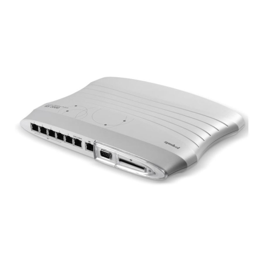
- Page 21 Power LED (PoE) The WS 2000 Wireless Switch provides six LAN ports and one WAN port. LAN Ports 1-4 provide 802.3af PoE support. Connect the Ethernet cable that will go into the Access Port into one of these four LAN ports.
- Page 22 WS 2000 Quick Installation Guide Each Ethernet port has two LEDs. The LED on the left side of the port indicates whether the port is transmitting at 10 Mbit/sec. or 100 Mbit/sec. The light is off when transmitting at 10 Mbit/sec. The light is on when transmitting at 100 Mbit/sec.
-
Page 23: Installing The Ap 100 Access Port
Installing the Branch Office Wireless Switch 3.4 Installing the AP 100 Access Port The AP 100 Access Port can be placed in a large variety of locations. Review installation plans to determine device placement and cable routing. Use the instructions in the section “Surface Mounting”... -
Page 24: Desk Mounting
WS 2000 Quick Installation Guide 3.4.2 Desk Mounting No mounting screws are necessary for mounting on a desk or other flat surface. However, Symbol does not recommend installation on such a surface because wall or ceiling mounting ensures better signal reception. - Page 25 7. Place the surface-mount light pipe screw through the center of the surface-mount cover and branding badge, and screw into the access port. 8. Attach the Ethernet cable that comes from the WS 2000 Wireless Switch. 3.4.4 Suspended Ceiling Tile (Plenum) Mounting Some installations require mounting the AP 100 Access Port above the ceiling tile.
- Page 26 To prevent damage to the device, use care when pulling cables attached to a mounted unit. 3.4.5 Power/Data (RJ-45) Connection The AP 100 Access Port receives power from the Ethernet cable. It supports the following Symbol- branded Power over Ethernet (PoE) devices: • Symbol Power Injector 1 Port...
-
Page 27: Configuring The Ws 2000 Wireless Switch
WS 2000 Wireless Switch Getting Started with the WS 2000 Wireless Switch This section provides just enough instruction to set up the WS 2000 Wireless Switch, connect an Access Port, and test communications with a single mobile unit and the wide area network (WAN). -
Page 28: Step 1: Setting Up Administrative Communication To The Switch
For optimum compatibility use Sun Microsystems’ JRE 1.4 or higher (available from Sun’s website), and be sure to disable Microsoft’s Java Virtual Machine if it is installed. The following screen is displayed. 4. Log in using “admin” as the User ID and “symbol” as the Password. - Page 29 Configuring the WS 2000 Wireless Switch 5. If the login is successful, the following dialog window is displayed. Enter a new admin password in both fields, and click the Update Password Now button. Once the admin password has been updated, the System Settings screen is displayed.
-
Page 30: Step 2: Setting The Basic Switch Settings
Step 3: Configuring the LAN Interface The first step of network configuration process is to figure out the topology of the LAN. The WS 2000 Wireless Switch allows the administrator to enable and configure four different subnets. The administrator can assign an IP address, port associations, DHCP settings, and security settings to each subnet. -
Page 31: Enable Subnet1
(such as the subnet configuration screens) where the administrator can set the data. Network Network (subnet) name is a descriptive string that should describe the subnet’s function. The WS 2000 Network Management System uses subnet names throughout the configurations screens. -
Page 32: Step 4: Configuring Subnet1
The Interfaces field also lists the WLANs that are associated with the subnet. Step 4: Configuring Subnet1 The WS 2000 Network Management System allows the administrator to define and refine the configuration of the enabled subnets. Each of four subnets (short for “subnetworks”) can be configured as an identifiably separate part of the switch-managed local area network (LAN). - Page 33 Configuring the WS 2000 Wireless Switch 2. Check to make sure that all the ports and WLAN1 are selected for this subnet. WLAN1 should automatically be included if the switch and the access port are communicating properly. If WLAN1 is not present in the list, check: •...
-
Page 34: Step 5: Configuring The Wan Interface
WAN port might connect to a DSL or cable modem to access the Internet. The WS 2000 Wireless Switch includes one WAN port. In order to set up communications with the outside world, select Network Configuration --> WAN from the left menu. The following WAN configuration page appears. - Page 35 Client is checked, the switch is limited to one WAN IP address. This choice is required when: • The host router or switch on the WAN is communicating with the WS 2000 Wireless Switch using DHCP. • The switch is interfacing with an Internet Service Provider (ISP) that uses DHCP addressing.
-
Page 36: Step 6: Enabling Wireless Lans (Wlans)
Step 6: Enabling Wireless LANs (WLANs) The WS 2000 Wireless Switch works either in a wired or wireless environment; however, the power of the switch is associated with its support of wireless networks. In order to use the wireless features... -
Page 37: Wireless Summary Area
Configuring the WS 2000 Wireless Switch To start the WLAN configuration process, select the Network Configuration --> Wireless item from the left menu. The following Wireless summary screen appears. Wireless Summary Area The top portion of the window displays a summary of the WLANs that are currently defined. This is the screen in which the administrator can enable or disable a WLAN. -
Page 38: Step 7: Configuring Wlan Security
WS 2000 Quick Installation Guide Use the Access Port Adoption area to assign Access Ports to a particular WLAN. The switch can adopt up to six Access Ports at a time, but the list of allowed Access-Port addresses (displayed in this area) can exceed six in number. -
Page 39: Setting The Authentication Method
Setting the Authentication Method The authentication method sets a challenge-response procedure for validating user credentials such as username, password, and sometimes secret-key information. The WS 2000 Wireless Switch provides two methods for authenticating users: 802.1x EAP and Kerberos. The administrator can select between these two methods. -
Page 40: Step 8: Testing Connectivity
WS 2000 Quick Installation Guide encryption of wireless data. However, networks that require more security are at risk from a WEP flaw. An unauthorized person with a sniffing tool can monitor a network for less than a day and decode its encrypted messages. -
Page 41: Where To Go From Here
WEP settings on the mobile device. 4. In the Web browser, enter a URL for a site (such as www.symbol.com) on the WAN. If the site does not appear, go to the WAN Stats screen (Status & Statistics --> WAN Stats) to review the status of the WAN connection. -
Page 42: Regulatory Information
WS 2000 Quick Installation Guide Regulatory Information All Symbol devices are designed to be compliant with rules and regulations in locations they are sold and will be labeled as required. Any changes or modifications to Symbol Technologies equipment, not expressly approved by Symbol Technologies, could void the user’s authority to operate the equipment. - Page 43 Hinweis: Benutzen Sie nur eine Symbol Technologies genehmigt Stromversorgung in den Ausgabe: 48VDC. Die Stromversorgung ist bescheinigt nach EN60950 mit SELV Ausgaben. FCC RF Exposure Guidelines To comply with FCC RF exposure requirements, antennas that are mounted externally at remote locations or operating near users at stand-alone desktop of similar configurations must operate with a minimum separation distance of 20 cm from all persons.
- Page 44 Italy requires a user license for outside usage. Statement of Compliance Symbol Technologies, Inc., hereby, declares that this device is in compliance with the essential requirements and other relevant provisions of Directives 1999/5/EC, 89/336/EEC and 73/23/EEC. Declaration of Conformities may be obtained from http://www2.symbol.com/doc/...
-
Page 45: Service And Support
Customer Support specialists cannot solve a problem, access to all technical disciplines within Symbol becomes available for further assistance and support. Symbol Customer Support responds to calls by e-mail, telephone or fax within the time limits set forth individual contractual agreements. - Page 46 Device serial number • Product name or model number • Software type and version number North American Contacts Inside North America, contact Symbol at: For sales and product information: Symbol Technologies, Inc. One Symbol Plaza Holtsville, New York 11742-1300 Telephone: 1-631-738-2400/1-800-SCAN 234...
- Page 47 Symbol Developer Program http://devzone.symbol.com/ Symbol Knowledge Base http://kb.symbol.com/register.asp For warranty and service information, contact the Symbol Support Center: telephone 1-631-738-6213 or 1-800-653-5350; fax: (631) 563-5410; or E-mail: support@symbol.com. Obtain additional information by contacting Symbol at: • 1-800-722-6234, inside North America •...
- Page 48 Symbol Technologies, Inc. One Symbol Plaza Holtsville, New York 11742-1300 http://www.symbol.com 72-70600-01 Document Revision A October 2004...
Need help?
Do you have a question about the WS 2000 and is the answer not in the manual?
Questions and answers