HP Series 200 Installation Manual
Hide thumbs
Also See for Series 200:
- Services and applications (316 pages) ,
- Hardware support document (95 pages) ,
- Instructions manual (7 pages)
Table of Contents
Advertisement
Quick Links
Advertisement
Table of Contents
Troubleshooting

Related Manuals for HP Series 200


Summary of Contents for HP Series 200
- Page 1 Installation Guide Series 200 Series 400 HP AdvanceStack Routers...
- Page 2 Installation Guide Hewlett-Packard Series 200 Routers Hewlett-Packard Series 400 Routers...
- Page 3 Installation Guide © Copyright Hewlett-Packard Safety Considerations Regulatory Information Company 1994. The product and related documenta- The product described in this All rights reserved. tion must be reviewed for document complies with specific inter- familiarization with safety markings national regulations. See the docu- This document contains proprietary and instructions before installation and ment section entitled “Regulatory...
- Page 4 Chapter 2: Router Description. Covers the general hardware features of all HP “rack and stack” routers, including port identities, status LED indications, resetting/clearing, and initialization sequence. Chapter 3: Troubleshooting. Provides basic tips, status LED interpre- tation and indicated actions, verifying LED operation, and various diag- nostic tests.
- Page 5 Installation Guide Preface...
-
Page 6: Table Of Contents
Contents 1. Installation and Initial Setup Phase 1: Ensure that You Have a Complete Set of Accessories . . . 1-3 Phase 2: Prepare the Network ..... . 1-4 Phase 3: Prepare the Router Hardware . - Page 7 A. Cables and Connectors HP Cables ....... . . A-3 Other Standard Cables .
- Page 8 B. Modem Configuration HP 35031A Support Link II ..... . B-2 HP 37212B Support Link ..... . . B-2 HP 50759A Support Link .
-
Page 9: Installation And Initial Setup
Installation and Initial Setup... - Page 10 Installation The installation and initial setup of your HP router involves these tasks: 1. Ensuring that you received a complete set of accessories with your router. (page 1-3). 2. Preparing the network (page 1-4). 3. Preparing the router hardware (page 1-6).
-
Page 11: Phase 1: Ensure That You Have A Complete Set Of Accessories
Installation Phase 1: Ensure that You Have a Complete Set of Accessories Phase 1: Ensure that You Have a Complete Set of Accessories Accessory kit. You should have one accessory kit containing the following: Brackets for mounting the router Screws for attaching the brackets to the router and to a rack AUI retainers Self-adhesive rubber feet BNC ‘‘T’’... -
Page 12: Phase 2: Prepare The Network
WAN link type (circuit type) and WAN link speed • Interface type (X.21, V.35, etc.) • HDLC address (DCE/DTE) for HP Point- to-Point links • X.121 address and connection ID (for X.25 links) • Quality of service (LLC1, LLC2, X.25) •... - Page 13 Installation Phase 2: Prepare the Network 4. Before you apply power to the router, connect all LAN and WAN links to the router. Verify the LAN cabling and that the WAN link terminating equipment is operational. Your WAN link service provider can verify that the WAN link is operating correctly.
-
Page 14: Phase 3: Prepare The Router Hardware
Installation Phase 3: Prepare the Router Hardware Phase 3: Prepare the Router Hardware The basic hardware installation steps are summarized below and detailed in the following pages. 1. Mount the router (page 1-7). 2. Connect a console (optional, depending on method for configuring and administering). -
Page 15: Mount The Router
Installation Phase 3: Prepare the Router Hardware A. Mount the Router 1. Make sure the router’s power cord is correct for your country’s ac power receptacle. Do not attach the power cord until the router is mounted. 2. Mount on a wall, rack, or table as follows: For Rack or Cabinet Mounting: Using a Phillips or cross-head screwdriver, attach the mounting brackets to the router with 10-mm #M4 screws. - Page 16 Installation Phase 3: Prepare the Router Hardware Single-Height Models These models are 4.3 cm (1.7inches) in height. Rack Mounting Mounting Bracket Mounting Bracket Figure 1-1. Rack Mount - Bracket Position Figure 1-2. Rack Mount - Back Out Wall Mounting Mounting Bracket Mounting Bracket Figure 1-3.
- Page 17 Installation Phase 3: Prepare the Router Hardware Double-Height Models These models are 8.9 cm (3.5 inches) in height. Rack Mounting Mounting Bracket Mounting Bracket Figure 1-5. Rack Mount - Bracket Position Figure 1-6. Rack Mount - Back Out Wall Mounting Mounting Bracket Mounting Bracket Figure 1-7.
-
Page 18: Connect A Console (Optional)
Installation Phase 3: Prepare the Router Hardware B. Connect a Console (Optional) When Is a Console Necessary? Connecting a console is necessary if your management of the router requires direct access through the console port by either a local opera- tor or by a remote operator using a modem. -
Page 19: Attach Network Cables
Installation Phase 3: Prepare the Router Hardware C. Attach Network Cables Depending on the model of router and the physical connections in your network, you will use one or more of the following interface options: AUI (page 1-12) BNC (page 1-14) Token Ring (page 1-16) FDDI (page 1-17) WAN (page 1-21) - Page 20 For single-height models, if the bottom of the router rests on a surface (such as a table) and you attach an HP transceiver directly to the AUI port (without an AUI cable), then attach the rubber feet you received in the accessory kit (page 1-3) to the bottom of the router to prevent the transceiver from supporting the weight of the router.
- Page 21 Installation Phase 3: Prepare the Router Hardware 1. Slide the AUI retainer (included) onto the connector posts on a transceiver (also called a “MAU”) that corresponds to your type of network cabling, or on an AUI cable that is attached to a transceiver (whichever will attach directly to the router).
- Page 22 Installation Phase 3: Prepare the Router Hardware Connecting a LAN to the BNC Interface: W a r n i n g To avoid an electrical shock hazard due to an ungrounded or improperly grounded LAN cable, ensure that the LAN cable is properly grounded.
- Page 23 Installation Phase 3: Prepare the Router Hardware 1. Ensure that the LAN cable is properly grounded. (Refer to ‘‘Safety Information’’ in the back of this manual.) Figure 1-12. BNC Connector -- Mid-Cable Figure 1-13. BNC Connector -- End-of-Cable 2. Attach a ThinLAN cable section to one side of a BNC ‘‘T’’ connector. 3.
- Page 24 Installation Phase 3: Prepare the Router Hardware Connecting a LAN to the Token Ring Interface LAN port with Token Ring interface Token Ring Cable Trunk Coupling Unit (TCU) Figure 1-15. LAN 802.5 Token Ring Connection 1. Secure the D-connector on the token ring cable to the token ring port by using the screws on the connector.
- Page 25 Phase 3: Prepare the Router Hardware Connecting an FDDI Ring to the FDDI Interface FDDI connections on HP routers use a dual-port FDDI interface with op- tional node bypassing. Node bypassing is achieved by using an optical bypass switch, also known as an “FDDI dual-switch module”. (For part number, refer to the release notes you received with your router or most recent software upgrade.) Using a bypass switch to connect your FDDI...
- Page 26 Connecting an FDDI Ring Directly to the Router: If you are not going to use a bypass switch, simply insert the modular plugs from your FDDI ring into the “MIC A” and “MIC B” FDDI ports on the HP Router MIC A MIC B...
- Page 27 Installation Phase 3: Prepare the Router Hardware Using an Optional Bypass Switch to Connect an FDDI Ring : If your FDDI connection includes an optional bypass switch, use the following steps: MIC B MIC A To port B of adjacent DAS station To port A of adjacent DAS station...
- Page 28 4. Connect the bypass cables to the FDDI ports as shown above. 5. Insert the DIN connector on the bypass unit into the Optical Bypass jack on the HP Router BR. N o t e The router will not detect the presence of a new connection to the FDDI ring until you reboot the router (which is covered later in this chapter).
- Page 29 Installation Phase 3: Prepare the Router Hardware Connecting a WAN to the WAN Interface The RS-232, V.35, X.21, or RS-422/449 cable for the 62-pin connector de- termines which interface standard is used on this port. WAN port for RS-232, V.24/V.28, V.35, WAN link terminating X.21, RS-422/RS-449, V.36 interfaces equipment (such as a...
-
Page 30: Plug In And Verify The Router Hardware
Installation Phase 3: Prepare the Router Hardware D. Plug In and Verify the Router Hardware When you power up a router that is in the factory default state (or if you clear it by using the Clear/Reset button combination--page 2-17), the router sends Bootp requests over all active ports for one minute. - Page 31 Installation Phase 3: Prepare the Router Hardware If the router is not in the factory default state when you apply power, it configures itself according to the configuration that was most recently saved. N o t e The router does not have a power switch. The router is powered on when you plug in the power cord, and automatically adapts to the correct ac voltage range for your power source.
- Page 32 Installation Phase 3: Prepare the Router Hardware Power and Self-Test LEDs 27290A R outer BR Ethernet/802.3 Po rt 1 Ethernet/802.3 Po rt 2 Ethernet/802.3 Po rt 3 Ethernet/802.3 Po rt 4 Enabled Enabled Enabled Enabled FDDI Por t Co nsole Po rt Optical By pass RS-2 32 MIC A...
- Page 33 Installation Phase 3: Prepare the Router Hardware 4. Press [Return] and wait for either the Main menu or (if a password has been set) the copyright screen, with a prompt for you to type the password. N o t e If your console is set to 9600 baud, you should have to press [Return] only once.
-
Page 34: Phase 4: Initialize And Verify The Router
Installation Phase 4: Initialize and Verify the Router Phase 4: Initialize and Verify the Router This phase begins with creating or modifying the configuration in a router. If you are managing a router through the console port or over the network, you will need to perform most or all of these steps. - Page 35 Installation Phase 4: Initialize and Verify the Router This phase involves these steps: A. Creating or modifying a configuration (page 1-28) B. Booting the router (page 1-30) C. Setting the correct time and date (page 1-33) D. Setting Manager and User passwords (page 1-34) E.
-
Page 36: Create Or Modify A Router Configuration
Installation Phase 4: Initialize and Verify the Router A. Create or Modify a Router Configuration The Shortest Path to a Functioning Configuration Configuring the router assigns values to the parameters that control its networking operation. The router is shipped from the factory with default configuration values. - Page 37 Installation Phase 4: Initialize and Verify the Router An Overview of Your Configuration Tools Quick Configuration: This utility creates a ‘‘getting started’’ configuration from a single screen that accesses the most commonly used router parameters. Some examples of Quick Configuration uses are: •...
-
Page 38: Boot The Router
Installation Phase 4: Initialize and Verify the Router B. Boot the Router After you create or change a configuration (pages 1-28 and 1-29), boot- ing the router causes it to replace the former configuration with the newly created one. Thus, in all cases, you must boot (or reboot) the router when you are ready to implement any changes you have made in the configuration. - Page 39 Installation Phase 4: Initialize and Verify the Router NCL prompt Figure 1-25. The Default NCL Prompt 2. Boot the router (with your new configuration) by typing boot at the NCL prompt and pressing [Return]. DEFAULT_CONFIG: boot [Return] 3. If your router does not have a Manager password, go to step 4. But if the router has a previously set Manager password, you must enter the password before booting can proceed.
- Page 40 Installation Phase 4: Initialize and Verify the Router 5. After the router boots (which takes only a few seconds), you will see the “speed sense” prompt: Waiting for speed sense. Press [Return] one or more times, as necessary, to re-synchronize the router with the console and to display the copyright screen.
-
Page 41: Set The Correct Time And Date (Optional)
Installation Phase 4: Initialize and Verify the Router C. Set the Correct Time and Date (Optional) Each time you power up the router, it starts with a default time and date. Whether you set the correct time and date or not depends on how you want the time and date to be maintained in your network. -
Page 42: Set Manager And User Passwords (Optional)
Installation Phase 4: Initialize and Verify the Router D. Set Manager and User Passwords (Optional) Passwords are optional. If no password is set, anyone can access the router for viewing, booting, changing the configuration, resetting statistics or variables, and using various commands. User and manager passwords have the following functions: User password: controls viewing of statistics, event log, MIB variables, and configuration parameters. - Page 43 Installation Phase 4: Initialize and Verify the Router Setting a Password: 1. From the Main menu (page 1-27), select the Network Control Language Interpreter (NCL). The NCL prompt then appears at the bottom of the screen. It will be either DEFAULT_CONFIG: as shown below, or another name you have already configured for your system.
-
Page 44: Verify Router Initialization
Installation Phase 4: Initialize and Verify the Router E. Verify Router Initialization N o t e The following is an overview of router initialization. For more on verification tests, refer to the User’s Guide for your router. Earlier in the startup process it is normal to verify proper router hard- ware operation. - Page 45 Installation Phase 4: Initialize and Verify the Router Examine the Event Log The event log is a tool you can use to help verify router initialization. Events posted to the event log indicate the success or failure of the configuration and initialization steps. Events are occurrences such as enabling circuits and services, changes in spanning tree states, and error conditions.
- Page 46 Installation Phase 4: Initialize and Verify the Router Upon entering the event log, you will see the first event for the most recent reboot at the top of the display. To navigate among the events displayed, use the following keys. [Return] Advance display by one page Roll back display by one page...
- Page 47 Installation Phase 4: Initialize and Verify the Router Examine the Statistics Screens To Verify That the Network Links are Operational This step helps to ensure that circuits and the bridging and routing services are transmitting and receiving data with zero or few errors. 1.
- Page 48 Installation Phase 4: Initialize and Verify the Router The following service statistics screens are available: Circuit Statistics: This screen provides summary data for each individual circuit, including how many bytes and frames were received and transmitted and how many frames contained errors. Per Second Statistics: This screen provides summary data for traffic volume on a per-second basis for each circuit on the router.
- Page 49 IPX servers. Note that if IPX SAP filters are being used in the network, your router may be restricted from learning about some servers. Also note that HP devices may be listed in the SAP table (used by HP OpenView network management during autodiscovery).
- Page 50 RGETDN: Use the Rgetdn command to display the DECnet router level 1 (intra-area) routing table for a local or remote HP router. Verify that the router has learned about all routers and end nodes in its area. Also, trace the paths to the destination nodes to verify that the hop counts and path costs are as expected.
- Page 51 10.100.100.1 is alive To send an AppleTalk Echo Protocol (AEP) request message (available on most HP routers) to a specific AppleTalk node address, use the NCL Atping command. For more on Ping and Atping, refer to the Operator’s Reference.
-
Page 52: Features And General Hardware Operation
Features and General Hardware Operation... -
Page 53: Features
On most models there is also one or more synchronous WAN ports supporting RS-232/V/24/V.28, V.35, X.21, or RS-422/RS-449/V.36 interfaces. These provide HP Point-to-Point, PPP, V.25 bis, SMDS, frame relay, and LAPB (X.25) connections to other routers. -
Page 54: Router Ports
Router Operation Features Router Ports The types of ports found on HP routers include one or more of the following: Ethernet/802.3 LAN Port with either an AUI-only or AUI/BNC interface: • AUI interface: For connecting through a transceiver to twisted-pair cable, thick or thin coaxial cable, or fiber-optic cable. -
Page 55: Additional Features
Router Operation Features Additional Features Detachable brackets for mounting in a 19-inch rack or on a wall. Automatic sensing of the power voltage range with no switches needed. The option to automatically recover from power failure while maintaining the current configuration. -
Page 56: Interpreting Front-Panel Leds
Activity (green): Blinks for each packet received or transmitted. The frequency shows the amount of traffic. In heavy traffic, it may appear to be lit all of the time. (In the HP Router TFR, the Activity LED is continually lit while the router is inserted in a ring.) Fault (amber): Lights if a failure occurrs on the network or router. -
Page 57: Interpreting Back-Panel Leds
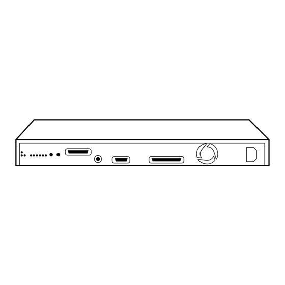
Router Operation Interpreting Back-Panel LEDs Interpreting Back-Panel LEDs WAN (synchronous) port Port status Console port Router status LEDs LEDs Reset and Clear LAN port with AUI buttons Power and BNC connectors Fan outlet Figure 2-3. Example of the Back Panel of a Single-Height Router LAN port FDDI port connectors LAN port with AUI and... - Page 58 Router Operation Interpreting Back-Panel LEDs Figure 2-5. Example of Router and Port Status LEDs in a Single-Height Router Figure 2-5. Example of Router and Port Status LEDs in a Double-Height Router Figure 2-7. Example of Port Status LEDs for an FDDI Port...
-
Page 59: Meanings Of Router Status Leds
Router Operation Interpreting Back-Panel LEDs Meanings of Router Status LEDs Power (green): Continually lit if the router is receiving power. (This is the same as ~Line On on the front.) Self-test (green) LED: Lights while the self-test is running (about one minute). -
Page 60: Meanings Of Port Status Leds
Router Operation Interpreting Back-Panel LEDs Meanings of Port Status LEDs N o t e Not all port types appear on all routers. Net Fail (Amber) LED: The Net Fail LEDs serve two functions: If all Net Fail LEDs are flashing, the router has failed and must be replaced. - Page 61 Router Operation Interpreting Back-Panel LEDs N o t e All Net Fail LEDs are lit while the Reset button is pressed. Tx (green) LED: This LED blinks each time a packet is transmitted through the related port. The frequency shows the amount of traffic. During periods of heavy traffic, it may look like it is lit all of the time.
- Page 62 Router Operation Interpreting Back-Panel LEDs FDDI Port "Thru" "Wrap" Figure 2-6. FDDI "Thru" and "Wrap A" Operation Thru (green): When lit, this LED indicates that packets are being received on the primary input line of port A and transmitted on the primary output line of port B.
- Page 63 Router Operation Interpreting Back-Panel LEDs Optical Bypass — Enabled (green): If you are using a bypass switch, the Optical Bypass—Enabled LED lights only when the switch is causing the FDDI ring to bypass the router. (The router will be bypassed when it is booting and when the FDDI circuit is disabled.) That is, the Optical Bypass LED is not lit when the FDDI circuit is enabled.
-
Page 64: Testing The Leds
Router Operation Testing the LEDs Testing the LEDs On most HP routers, all LEDs should be lit while you are pressing the Reset button. On the HP Router ER, TR, and SR, pressing the Reset button should light the following LEDs:... -
Page 65: Resetting The Router, Clearing The Passwords, And Clearing The Router
Router Operation Resetting the Router, Clearing the Passwords, and Clearing the Router Resetting the Router, Clearing the Passwords, and Clearing the Router Resetting the router: Boots the router, regardless of the current operating mode. Clearing the password(s): Removes the current password(s), if any, without interrupting the current state of the router. -
Page 66: To Reset The Router
Router Operation Resetting the Router, Clearing the Passwords, and Clearing the Router To Reset the Router Press and release the Reset button on the back of the router. (Turning the power off, then on has the same effect as pressing the Reset button.) Resetting does the following: Lights the Fault and Net Fail LEDs while the Reset button is pressed. -
Page 67: To Clear The Manager And User Passwords
Router Operation Resetting the Router, Clearing the Passwords, and Clearing the Router To Clear the Manager and User Passwords Use a non-conducting, pointed implement such as a wooden pencil or a toothpick to press and release the recessed Clear button. (Refer to figure 2-9 on page 2-14.) Access to the router will no longer be limited by a password. -
Page 68: To Clear The Router
Router Operation Resetting the Router, Clearing the Passwords, and Clearing the Router To Clear the Router The combination of the Reset and Clear buttons restores all factory defaults, including configuration defaults; removes the manager and user passwords; initiates transmission of a series of Bootp requests to facilitate (optional) automatic configuration from a remote source. - Page 69 Router Operation Resetting the Router, Clearing the Passwords, and Clearing the Router 4. When you see the message ‘‘Waiting for speed sense’’, press [Return] to display the Main menu (figure 1-24 on page 1-27). (You may need to press [Return] more than once to get console access again.) C a u t i o n The Reset-Clear combination erases the current configuration and...
-
Page 70: Initialization Sequence
Router Operation Initialization Sequence Initialization Sequence Whenever the router is powered on, or when its Reset button is pressed: 1. The Power LED indicates when power is on. 2. The router automatically goes through a self-test, which takes about one to three minutes. (The Self-test LED is lit during this step.) 3. -
Page 71: Troubleshooting
Troubleshooting... -
Page 72: Introducing Router Troubleshooting Features
Troubleshooting Introducing Router Troubleshooting Features Introducing Router Troubleshooting Features On all router models, the LED error patterns described in this chapter indicate specific error conditions that in some cases require either a recovery procedure done by the operator or replacement of the router. Certain later router models also can display error messages indicating FLASH memory problems that require cycling the power, downloading new operating code, or replacing the router. -
Page 73: Basic Troubleshooting Tips
Troubleshooting Basic Troubleshooting Tips Basic Troubleshooting Tips N o t e Some of the router’s console commands are used for the troubleshooting instructions in this chapter. Refer to “Connect a console” (page 1-10) for details on connecting to the console port. For information on the Configuration Editor and the Network Command Language Interpreter (NCL), refer to the User’s Guide for your router. -
Page 74: Interpreting Led Error Patterns
Troubleshooting Interpreting LED Error Patterns Interpreting LED Error Patterns When power to the router is cycled or the Reset button is pushed, LED error patterns have the meanings shown in table 3-1 below. Table 3-1. LED Error Patterns During Initialization Initialization Fault LED Patterns Diagnostic Tips Power... - Page 75 Troubleshooting Interpreting LED Error Patterns Table 3-2. LED Error Patterns During Operation Operational fault LED patterns Diagnostic Tips Power Self-test Fault Net Fail Unlit Check power cord and power source. If they are OK, replace the router. Unlit Software failure. Press Reset button or enter NCL Boot Unlit command if router is not set to reboot automati cally.
-
Page 76: Interpreting Error Messages On The Hp Advancestack Router 200 Series
Troubleshooting Interpreting ERROR Messages on the HP AdvanceStack Router 200 Series Interpreting ERROR Messages on the HP AdvanceStack Router 200 Series N o t e This section applies to the following routers: HP Router PR HP Router FR HP Router TFR... -
Page 77: Recoverable Self-Test Failures
FLASH memory that may be corrected by cycling the power. If, after the power is cycled, the problem persists, then it may be corrected by down- loading new operating code. In this case, contact your HP dealer or service provider. -
Page 78: Non-Recoverable Self-Test Failures
Non-Recoverable Self-Test Failures If the router persists in a non-operating state and/or displays any error message other than the five listed above, then there may be a hardware problem that requires replacement of the router. Contact your HP dealer or service provider. -
Page 79: Verifying Led Operation
Verifying LED Operation on Other Router Models Use this method to verify the LEDs on HP routers other than the HP Router ER, TR, and SR models. Press and hold the Reset button. All LEDs should light. If any LED does not light, either the LED or its driver circuit has failed. -
Page 80: Diagnostic Tests
If the Self-test LED does not light and then turn off after one to three minutes, the router is faulty. If you have tried to change the product operating code or have access to the code on another HP router, try updating it again. If not, then replace the router. -
Page 81: Testing The Router's Ports
Troubleshooting Diagnostic Tests Testing the Router’s Ports The following tests require loopback connectors. The type of loopback connectors depends on which ports are in use and need testing. See illustrations and part numbers under “Loopback Connectors” (page A-20). To test a WAN port: 1. -
Page 82: Troubleshooting A Terminal Or Modem Connection
Troubleshooting Diagnostic Tests To test an FDDI port: 1. Detach the network connection and attach a loopback connector to either FDDI port. (Refer to ‘‘Loopback Connectors’’ on page A-20.) 2. Press the Reset button to reset the router. 3. If the Net Fail LEDs for the tested port light, the port is faulty. Replace the router. - Page 83 [Return] again. If pressing [Return] four or five times does not display either the copyright or Main menu screen, then ensure that you are using the correct console cable. (Refer to “HP Cables” on page A-3.) If the cable is correct, then repeat this procedure for each other baud rate available for your terminal until you find a rate that gives you a successful connection.
- Page 84 Troubleshooting Diagnostic Tests Test Router’s Console Port: 1. Detach the console cable from the router. 2. Attach the console port’s loopback connector to the router. (Refer to “Loopback Connectors” on page A-20). 3. Press the Reset button on the back of the router. C a u t i o n Resetting the router causes bridging and routing tables to be reset.
-
Page 85: Testing A Transceiver On An Ethernet/802.3 Port
This test can be done with transceivers (sometimes termed MAUs) such as the HP 28685B EtherTwist Transceiver, the HP 28641B ThinLAN Transceiver, and the HP 28683A Fiber-Optic Transceiver. (Some transceivers have a loopback test switch that must be set to correspond to these requirements.) 1. -
Page 86: Testing A Link
The router provides two other specific link tests, Ping and Telnet, described below. Note that you can use HP network management software to test the link. Refer to the help screens for the software. - Page 87 2. At the NCL prompt, enter one of the following commands: • For LAN and WAN circuits: get cct.cct-name.mac_addr [Return] • For FDDI circuits (HP Router BR only): get cct.fddi-name.ieee.addr [Return] where: cct-name or fddi-name is the configured circuit name for the port. Examples of circuit names are ETHER1, WAN1, TOKEN1, and FDDI1.
- Page 88 Troubleshooting Diagnostic Tests Ping Ping is a network-layer test that sends an Internet Control Message Protocol (ICMP) echo request message to another node that has an IP address and is able to respond to an ICMP echo request message. The router must have IP routing configured in order to use this test.
- Page 89 Telnet is an upper-layer service that allows you to interact with a remote node’s console interface, by establishing a virtual terminal connection. You make a console connection from an HP router that has IP routing and a Telnet session configured to a router or end node that has Telnet service and is suspected of not routing successfully.
-
Page 90: Cables And Connectors
Cables and Connectors... - Page 91 Note that each pin-out does not necessarily match the pin-out for the corresponding HP cable, but cables manufactured to follow the minimum pin-out will function correctly. Loopback connec-...
-
Page 92: Hp Cables
WAN port Back-to-Back test cable for WAN port For 62-pin female WAN port(s) 5061-2556 (5 meters) connecting to HP routers having a 62- included on most HP routers pin synchronous WAN port or the and theHP Remote Bridge RB... -
Page 93: Other Standard Cables
2 Signals DTR (pin 20) and RTS (pin 4) must be on, or high, on your terminal or in your terminal emulation program. 3 Two cables are required for dual attachment to another HP router having an FDDI port or an adjacent DAS. -
Page 94: Cable And Connector Pin-Outs
Cables and Connectors Cable and Connector Pin-Outs Cable and Connector Pin-Outs Router Console Port Connector Pin-Outs CCITT CHS GND RS-232 Modem Cable—Minimum Pin-Outs Modem end Router end 25-pin male 25-pin male CD or DCD DRS; typically on V.24 (European) modems... -
Page 95: Null Modem" Cable For Terminal/Pc With 25-Pin Connector-Minimum Pin-Out
Cables and Connectors Cable and Connector Pin-Outs RS-232 “Null Modem” Cable for Terminal/PC with 25-Pin Connector—Minimum Pin-Out Terminal/PC end Router end 25-pin male 25-pin male RS-232 “Null Modem” Cable for Terminal/PC with 9-Pin Connector—Minimum Pin-Outs Terminal/PC end Router end 9-pin female 25-pin male... -
Page 96: Cable For Hp Portable (110) And Portable Plus-Minimum Pin-Outs
Cables and Connectors Cable and Connector Pin-Outs RS-232 Cable for HP Portable (110) and Portable Plus—Minimum Pin-Outs Computer End Router End 9-Pin Male 25-Pin Male Null-Modem Adapter for Use with Modem Cable—Minimum Pin-Outs Modem Cable End Router End 25-Pin Female... -
Page 97: Router Aui Lan Port Definition
Voltage Plus Chassis Ground For this connection, you can use: HP 92264D (1-meter ThinLAN AUI extension, pin 4 not connected) HP 92254A through H (6-meter through 48-meter ThickLAN cables) HP 92254J (5-meter ThinLAN AUI cable, pin 4 not connected) Some longer cables may have all 15 pins wired. See the IEEE 802.3 stand- ards document for definitions of the pins not shown here. -
Page 98: Rs-449/422 Wan Cable-Minimum Pin-Outs
Cables and Connectors Cable and Connector Pin-Outs RS-449/422 WAN Cable—Minimum Pin-Outs WAN link Router end RS-449 Signal Name end 37-pin male 62-pin male and Circuit Send Data, A Send Timing, A Receive Data, A Request to Send, A Receive Timing, A Clear to Send, A Reserved Data Mode, A... -
Page 99: Wan Cable-Minimum Pin-Outs
Cables and Connectors Cable and Connector Pin-Outs V.35 WAN Cable—Minimum Pin-Outs WAN link Router CCITT Signal Name and Circuit 34-pin male 62-pin male Signal Ground Ready to Send Clear to Send Data Mode Receiver Ready 108.2 Terminal Ready Reserved Send Data, A Receive Data, A Send Data, B Receive Data, B... -
Page 100: Wan Cable-Minimum Pin-Out
Cables and Connectors Cable and Connector Pin-Outs X.21 WAN Cable—Minimum Pin-Out WAN link end Router end X.21 Signal Name and Circuit 15-pin male 62-pin male Send Data, A Control, A Receive Data, A Indicator, A Send Timing, A Ground Send Data, B Control, B Receive Data, B Indicator, B... -
Page 101: Wan Cable-Minimum Pin-Outs
Cables and Connectors Cable and Connector Pin-Outs RS-232 WAN Cable—Minimum Pin-Outs WAN link end Router end EIA and Signal Name 25-pin male 62-pin male Send Data Receive Data Request to Send Clear to Send Data Mode Signal Ground 22-27 Receiver Ready Reserved Reserved Reserved... -
Page 102: Back-To-Back Test Cables
Back-to-Back Test Cables Two 5-meter, back-to-back, synchronous test cables are available from HP. These cables allow you to connect any HP router having a (62-pin) synchronous WAN port to another HP router (or an HP Remote Bridge) having the same port type, without using a modem eliminator, for up to 60 meters (200 feet). -
Page 103: Hp 5061-2556 Back-To-Back Test Cable For 62-Pin Connector-Minimum Pin-Outs
External, and the other must have it configured to Internal. 62-pin male 62-pin male Note: On the HP Router PR, FR, and TFR, Clock Source is automatically configured to the proper setting (Internal or External) when using the HP 5061-2556 test cable. On other models, you must use the Configuration Editor to change the Clock Source setting. -
Page 104: Hp 5061-2557 Back-To-Back Test Cable For 62-Pin Connector-Minimum Pin-Outs
DCE and the WAN port on the other router must have it config- ured to DTE. In addition, this router must have Clock Source configured to Internal, and the HP Router CR must have it configured to External. For the pinouts of this cable, turn the page. - Page 105 Cables and Connectors Cable and Connector Pin-Outs HP Router PR end HP Router CR end 62-pin male 15-pin male Shield Shield N o t e : In the cable, each of the differential signal pairs (SDA and SDB, RDA and RDB, and so on) must be twisted pairs of wire.
-
Page 106: Router Token Ring/802.5 Lan Port Definition
Cables and Connectors Cable and Connector Pin-Outs Router Token Ring/802.5 LAN Port Definition This port accepts the standard nine-pin subminiature D-connector for shielded twisted-pair token-ring cable. Pin Definition of Token Ring Connector Nine-Pin Token Ring Connector Signal Data In A Ground 5V Out Ground... -
Page 107: Fddi Optical Bypass Din Connector Pinouts (Hp Part Number 5063-2488
Cables and Connectors Cable and Connector Pin-Outs FDDI Optical Bypass DIN Connector Pinouts (HP Part Number 5063-2488) Figure A-2. FDDI Bypass Mini DIN Connector Pinouts pin 1 switch positive (5V, 400 mA max) pin 2 pin 3 switch ground pin 4... -
Page 108: Fddi Cable
Cables and Connectors Cable and Connector Pin-Outs FDDI Cable Medium Interface Connectors (MIC) Figure A-3. Example of FDDI Cable A-19... -
Page 109: Loopback Connectors
Cables and Connectors Cable and Connector Pin-Outs Loopback Connectors For the Console Port HP part number 5062-3355; pin connections: pin 2 to pin 3 pin 4 to pin 5 to pin 8 pin 6 to pin 20 to pin 22... - Page 110 Cables and Connectors Cable and Connector Pin-Outs For a WAN Port HP part number 28606-63007; pin connections: pin 9 to pin 23 pin 10 to pin 27 pin 11 to pin 50 pin 12 (not used) to pin 7 (not used)
-
Page 111: Modem Configuration
Modem Configuration... -
Page 112: Hp 35031A Support Link Ii
Modem Configuration HP 35031A Support Link II At the router end: Configure SOFT OPTION 6 to 1. Configure SOFT OPTION 15 to 2. Configure SOFT OPTION 16 to 2. Configure SOFT OPTION 20 to 2. Configure SOFT OPTION 21 to 2. -
Page 113: Hayes 2400 Smartmodem
Modem Configuration Hayes 2400 Smartmodem At the router end: Configure with a terminal or PC using the following sequence: at&f&c1&d2&s1 ats0=1 Depress the ANS button. The red light should go ON. At the user end: Configure with a terminal or PC using the following sequence: at&f&c1&d2&s1 Black Box V.32 9600 Async. -
Page 114: Specifications
Specifications... -
Page 115: Physical (Without Brackets
Router Maximum Maximum Frequency Model current at current at Range 100-120 Vac 200-240 Vac HP Router ER 0.6 amp 0.45 amp HP Router TR 0.9 amp 0.6 amp HP Router LR 0.9 amp 0.5 amp HP Router SR 0.9 amp 0.6 amp... -
Page 116: Environmental
Specifications Environmental Operating Non-Operating Temperature 0°C to 55°C –40°C to 70°C (32°F to 131°F) (–40°F to 158°F) Relative humidity 15% to 95% at 40°C 90% at 65°C (104°F), non-condensing (149°F) Altitude 4.6 km (15,000 ft) 4.6 km (15,000 ft) Electromagnetic Emissions Countries ER, TR, &... -
Page 117: Data Communications Specifications
Specifications Data Communications Specifications Cable Interfaces Specifications Console port EIA RS-232 or CCITT V.24/V.28, asynchronous Ethernet/802.3 ports IEEE 802.3 standards, Ethernet 1.0 and 2.0 Token Ring/802.5 IEEE 802.5 standards for shielded twisted pair (TR only) WAN port EIA RS-232 and CCITT V.24/V.28, synchronous, (with the appropriate cable) EIA RS-422/449 and CCITT V.36, CCITT X.21,... - Page 118 Hewlett-Packard has applied to the following agencies for certification for use on X.25 packet-switching networks. Certifications were still in progress at the time of printing. Please contact your local HP representative for latest certification status. North America Telenet, Tymnet, Infonet, DDN...
-
Page 119: Fddi Cable Attachment Configurations
FDDI Cable Attachment Configurations... - Page 120 FDDI Cable Attachment Configurations If your HP router has an FDDI port, you can attach it to the FDDI network in several different ways. The three examples described below are standard FDDI methods for FDDI dual-attach station (DAS) devices, and are not specific to any HP router.
-
Page 121: Dual-Attach Station (Das
FDDI Cable Attachment Configurations Dual-Attach Station (DAS) Dual-Attach Station (DAS) Adjacent DAS HP router with Adajacent DAS (router with FDDI) FDDI port (router with FDDI) Figure D-1. Example of Dual-Attach Station Connections This configuration gives you optional use of the optical bypass switch (page 1-19) to prevent ring wrap if an FDDI circuit becomes non-opera- tional. -
Page 122: Single-Attach Station (Sas
FDDI Concentrator Connect either ‘‘A’’ or ‘‘B’’ to any ‘‘M’’ port on the concentrator HP router with an FDDI port Figure D-2. Example of Single-Attach Station Connections This configuration avoids the need for an optical bypass switch (page 1- 19) because the FDDI concentrator provides the isolation of the router from the dual ring (to prevent ring wrap) if the router’s FDDI circuit be-... -
Page 123: Dual-Homed Connection
... . HP router with FDDI port Figure D-3. Example of Dual-Homed Connection This configuration: avoids the need for an optical bypass switch (page 1-19) provides redundancy so that failure of one cable or concentrator will not break the router’s connection to the dual ring... -
Page 124: Safety Information
Safety Information Safety Information Safety Symbols Documentation reference symbol. If the product is marked with this symbol, refer to the product documentation to get more information about the product. WARNING A WARNING in the manual denotes a hazard that can cause injury or death. - Page 125 Informations concernant la sécurité Informations concernant la sécurité Symboles de sécurité Symbole de référence à la documentation. Si le produit est marqué de ce symbole, reportez- vous à la documentation du produit afin d’obtenir des informations plus détaillées. AVERTISSEMENT Dans la documentation, un AVERTISSEMENT indique un danger susceptible d’entraîner des dommages corporels ou la mort.
-
Page 126: Hinweise Zur Sicherheit
Hinweise zur Sicherheit Hinweise zur Sicherheit Sicherheitssymbole Symbol für Dokumentationsverweis. Wenn das Produkt mit diesem Symbol markiert ist, schlagen Sie bitte in der Produktdokumentation nach, um mehr Informationen über das Produkt zu erhalten. VORSICHT Eine VORSICHT in der Dokumentation symbolisiert eine Gefahr, die Verletzungen oder sogar Todesfälle verursachen kann. -
Page 127: Considerazioni Sulla Sicurezza
Considerazioni sulla sicurezza Considerazioni sulla sicurezza Simboli di sicurezza Simbolo di riferimento alla documentazione. Se il prodotto è contrassegnato da questo simbolo, fare riferimento alla documentazione sul prodotto per ulteriori informazioni su di esso. PERICOLO La dicitura PERICOLO denota un pericolo che può causare lesioni o morte. -
Page 128: Consideraciones Sobre Seguridad
Consideraciones sobre seguridad Consideraciones sobre seguridad Símbolos de seguridad Símbolo de referencia a la documentación. Si el producto va marcado con este símbolo, consultar la documentación del producto a fin de obtener mayor información sobre el producto. ADVERTENCIA Una ADVERTENCIA en la documentación señala un riesgo que podría resultar en lesiones o la muerte. - Page 129 Safety Information Safety Information...
-
Page 130: Regulatory Statements And Warranty
Re-orient the receiving antenna. Relocate the equipment with respect to the receiver. Plug the equipment and re- ceiver into different branch circuits. Consult your dealer or an experienced technician for additional suggestions. VCCI Class 2 (Japan Only) For the HP Router ER/TR/SR... -
Page 131: European Community
This equipment complies with ISO/IEC Guide 22 and EN55022 Class A. N o t e The HP router models PR, FR, TFR, LR, and BR are class A products. In a domestic environment, this product may cause radio interference, in... - Page 132 The following Declarations of Conformity complies with ISO/IEC Guide 22 and EN 45014. Declarations It identifies the product, the manufacturer’s name and address, and the applicable of Conformity specifications that are recognized in the European community. HP Router ER HP Router TR HP Router SR...
- Page 133 Regulatory Statements and Warranty HP Router PR HP Router FR HP Router TFR HP Router LR HP Router BR...
- Page 134 HP receives notice of such defects during the warranty period, HP will, at its option, either repair or replace products that prove to be defective. Should HP be unable to repair or replace the product within a reason- able amount of time, customer’s alternative exclusive remedy shall be a refund of the purchase price upon return of the product.
- Page 135 Please contact your HP authorized LAN dealer or HP representative for the current list of tested products. HP relies in part upon information from the suppliers of non-HP prod- ucts and makes no warranty, expressed or implied, with respect to the operation of these products or their compliance with worldwide regula- tory requirements.
- Page 136 Hewlett-Packard warrants that the software or firmware, when properly installed, will not fail to execute their programming instructions for a period of ninety (90) days from the date of purchase from HP or its Authorized Reseller. If HP receives notice of defects within the warranty period, HP will at its option either repair or replace the defective soft- ware or firmware or refund the purchase price.
-
Page 137: Index
Index password ...1-25 See also command 10Base-T ...A-3 speed sense ...1-24 boot, effect on configuration ...1-28 Bootp request ...1-22, 2-17 accessories kit ...1-3, 1-7 Bootp server acoustical specifications ...C-3 See configuration AEP request ...1-43 Breath-of-Life packet ...3-5 altitude specifications ...C-3 bridging ...2-2 ANSI terminal ...1-5 bridging, enabled ...2-18... - Page 138 Index Clear/Reset ...1-22 port ...2-3 clearing the router ...1-22 RS-232 interface ...2-3 clock, router ...2-19 console cable ...3-12 -- 3-13 collisions ...2-9, 3-5 console port, test ...3-12 command Copyright ...1-2 Atping ...1-43 copyright screen ...1-25, 1-32 Boot ...1-31, 3-5 cord, power ...1-3 Crash ...3-5 Crash command ...3-5 Exit ...1-33...
- Page 139 FDDI ...2-2 – 2-3, 2-9 See HP Router ER attached methods ...D-2 HP cables ...A-3 boot ...1-20 HP Router ER ...1-23, 3-9 bypass switch ...1-17 – 1-19, 2-3 HP Router FR ...3-6 concentrator ...D-4 -- D-5 HP Router PR ...3-6 DAS station ...1-18 –...
- Page 140 Index See network management manager password ...2-17 LAN 802.3 interface ...1-14, 2-2 See password LAN 802.5 ...2-2, 2-3, 2-9 manuals ...1-3 LAN cable ground ...1-14 – 1-15 LAN port, test ...3-11 See transceiver LAN types supported ...C-4 MIB ...3-16 LAPB ...2-2 MIB variables ...1-34 LED ...2-17, 3-3 Activity ...2-5...
- Page 141 Index manager ...1-31, 1-35, 2-17 resetting, caution ...3-14 reset ...2-15 restart setting ...1-35 See boot and resetting user ...1-35, 2-17 retainer, AUI ...1-12, 1-13 PC used as a console device ...A-3 – A-4, Rget commands ...1-41 – 1-42 A-6 – A-7 Rgetatr ...1-42 Rgetda ...1-42 physical address...
- Page 142 Index SMDS ...2-2 terminator, BNC ...1-15 SNMP ...1-41 Test ...1-34 software failure ...2-8 test, LED ...2-13 spanning tree ...1-29, 1-37, 2-18 TFTP ...2-16 specifications ...C-1 – C-5 TFTP server ...1-22 speed sense ...1-24 -- 1-25, 1-32, 2-15, 2-18 -- thin coaxial LAN connection ...A-3 2-19, 3-13 Thru, FDDI ...2-11 speed sense, reset ...3-12...
- Page 143 Index waiting for speed sense ...3-12 – 3-14 wall mount ...1-7 – 1-9 WAN ...2-9 cable ...C-4 loopback connector ...A-21 port ...A-3, A-9 – A-15, A-21, C-4 test cable ...A-3 WAN interface ...1-11, 1-21 WAN port, test ...3-11 Warranty ...1-2 weight ...C-2 Wrap, FDDI ...2-11, D-4 wrapping, FDDI ring ...1-17...
- Page 144 ©Copyright 1994 Hewlett-Packard Company Printed in Singapore 7/94 Manual Part Number 5962-8307...
Need help?
Do you have a question about the Series 200 and is the answer not in the manual?
Questions and answers