
Related Manuals for Wacker Neuson DPU 7060SC


Summary of Contents for Wacker Neuson DPU 7060SC
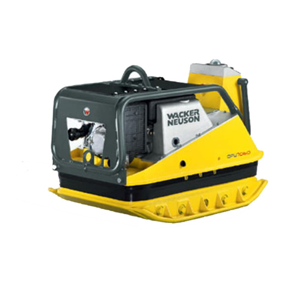
- Page 1 0203971en 11.2006 Vibratory Plate DPU 7060SC Operator´s Manual...
-
Page 3: Operating Instructions
Operating instructions Foreword For your own safety and protection from bodily injuries, carefully read, understand and follow the safety instructions in this manual. Please operate and maintain your Wacker machine in accordance with the instructions in this manual. Your Wacker machine will reward your attention by giving trouble-free operation and a high degree of availability. -
Page 4: Table Of Contents
Table of contents Foreword Safety instruction General instructions ................4 Operation ....................4 Safety checks ..................6 Maintenance ..................7 Transport ....................7 Maintenance checks ................8 Technical Data Description Applications ..................11 Dimensions ..................11 Max. admissible inclination ..............11 Description of function ................ - Page 5 Table of contents Maintenance Maintenance schedule ............... 25 Motoröl ....................26 Batterie ....................27 Hydrauliksteuerung ................27 Exciter ....................28 Assembly instruction ................29 Exciter V-belt ..................29 Faults Disturbance on the machine console ..........30 Disturbance on sender ............... 31 Forward speed too low ...............
-
Page 6: Safety Instruction
Safety instruction Safety instruction for the use of vibratory plates with combustion engines General instructions 2.1.1 Vibratory plates may only be operated by persons who ∗ are at least 18 years of age ∗ are physically and mentally fit for this job ∗... - Page 7 Safety instruction 2.2.4 The operator has to stop the engine of the vibratory plate before going on breaks. The machine has to be placed such that it cannot turn over. 2.2.5 Stop engine before filling fuel tank. When refilling fuel tank, do not allow fuel to come into contact with the hot part of the engine or spill onto the ground.
-
Page 8: Safety Checks
Safety instruction 2.2.14 When traveling backwards the operator has to guide the vibration plate laterally by its guide handle so that he will not be squeezed between the handle and a possible obstacle. Special care is required when work ing on uneven ground or when compacting coarse material. Make sure of a firm stand when operating the machine under such conditons. -
Page 9: Maintenance
Safety instruction Maintenance 2.4.1 Only use original spare parts. Modifications to this machine including the adjustment of the maximum speed set by the manufacturer are subject to the express approval of WACKER. In case of nonobservance all liabilities shall be refused. 2.4.2 All drive units have to be switched off before carrying out maintenance jobs. -
Page 10: Maintenance Checks
Safety instruction 2.5.3 When being transported on vehicles, precautions have to be taken that vibration plates do not slip or turn over. Maintenance checks 2.6.1 According to the conditions and frequency of use, vibratory plates have to be checked for safe operation at least once a year by skilled technicians, such as those found at WACKER-service depots and have to be repaired if necessary. -
Page 11: Technical Data
Technical Data Technical Data DPU 7060SC Item no. 0008927 ... Operating weight without extension plates (600 mm) kg: with extension plates - narrow (660 mm) kg: with extension plates - Serial (770 mm) kg: with extension plates - wide (880 mm) kg: Vor- und Rücklauf... - Page 12 Technical Data DPU 7060SC Electrical system Battery Special Wacker-battery for vibro plates, - 12 V - 55 Ah Alternator Charging rate max. 11,4 Charging voltage Starter Starter motor Direct voltage Hydraulic control Hydraulic oil Renolin MR 520 Oil quantity Remote control...
-
Page 13: Description
Description Description Applications The vibratory plate is excellently suited for the compaction of most types of soils, including semi-cohesive soils, both in trench and in surface compaction operations, as well as for the vibrating of heavy interlocking concrete blocks or paving stones. Dimensions Max. -
Page 14: Description Of Function
Description Description of function Advance Reverse Left turn Right turn The vibration needed for the soil compaction is generated in the exciter (9). The exciter is tightly bolted to the lower mass (8). It has been designed as a central exciter, therefore allowing - by ways of a relative rotation between the excentric weights (1) - the rotation of the direction of the vibrations. - Page 15 Description The automatic V-belt pulley (3) combined with the centrifugal clutch ensures optimum tension of the exciter V-belt during operation and relief of the tension of the exciter V-belt when the machine is being relocated or transported. Moreover, the automatic V-belt pulley (3) automatically adapts to the V-belt flanks in line with the wear and thus makes the entire drive from the engine (12) to the exciter (9) maintenance-free.
-
Page 16: Infrared Remote Control
Description Infrared remote control Always keep operating elements dry, clean and free of oil or grease. Above all do not cover receiver or transmitter (remote control) under any circumstances. The machine can be operated only with a remote controller. Operational elements – Machine console: a = Receiver eye with cover b = LED-Ring... -
Page 17: Charging The Battery
Description Charging the battery There are two ways to charge the battery: Spiral cable Through the spiral cable (in the machine console) with the option of operating the machine at the same time. Charging time maximum 40 minutes. Green LED (k) on the sender will extinguish when the battery is recharged. -
Page 18: Changing The Transmission Channel
Description Changing the transmission channel You can set the sending channel in the sender and on the decoder on the switch (v). To change the channel on the sender, open the sender and move it to one of the three possible positions.. The decoder must be set to the same channel as the transmitter. -
Page 19: Transport To Work Site /Recommendations On Compaction
Transport to work site /Recom- Transport to work site /Recommendations on compaction Transport to work site Conditions: ∗ To transport the vibration plate, only use suitable lifting equipment with a minimum load-bearing capacity of 700 kg. ∗ Always switch off engine before transporting the machine! ∗... -
Page 20: Recommendations On Compaction
Transport to work site /Recommendations on compaction Recommendations on compaction 5.2.1 Ground conditions The max. compaction depth depends on several factors relating to the ground condition, such as moisture, grain distribution etc, it is therefore not possible to specify exact values. Recommendation: In each case determine the max. -
Page 21: Operation
Operation Operation Conditions for starting Engine oil: Check oil level with dip stick (15) and replenish with oil through filler neck (16) if necessary (see Technical Data). The machine must be level and the engine stopped before proceeding with the oil level check. Fuel: When pouring diesel fuel into the fuel nozzle (17), maintain absolute cleanliness. -
Page 22: Activating The Machine
Operation Activating the machine Machine console Press the ”I” button for at least one second – the yellow LED ring (b) will illuminate. Sender Move the rocker switch (h) forward to ”I” – the green LED (m) starts blinking regularly. Point the sender at the receiver eye (a) on the machine –... -
Page 23: Starting
Operation Starting Leave the machine’s safety zone. Point the sender toward the receiver eye (a). Hold the starter button (i) depressed until the vibratory plate runs. The motor will automatically assume the standard speed when at least one of the two joysticks (g) is moved from the center position. Wait until the engine stops before repeating the starting procedure. -
Page 24: Steering The Machine
Operation Steering the machine The operator determines the machine’s direction of travel by moving the two joysticks (g) on the sender. The vibratory plate will compact the ground while moving forward, moving in reverse, spinning to the left, spinning to the right, or simply standing still. Advance Reverse Left turn... -
Page 25: Turning Off Engine
Operation Turning off engine Sender: Let go of both joysticks (g). Switch off the sender by moving the rocker switch (h) from the ”I” position to the ”0” position – green LED (m) extinguishes. LEDs (n + o) illuminate brieflyf Machine Console: Press ”0”... -
Page 26: External Starting
Operation External starting Observe the following connection sequence when using an external battery to start the engine: Only 12 V batteries may be used. The use of e.g. a 24 V truck battery will lead to an explosion of the vibro plate battery! Only use insulated jumper cables! Stop engine. -
Page 27: Maintenance
Maintenance Maintenance Maintenance schedule Check all external screw connections for tight fit appox. 8 hours alfter first operation. Component Maintenance work Maintenance interval approx. 20 hours after Valve clearance Check, set to 0,1 mm when engine is cold. initial start-up 25 hours after initial Drive engine First oil change and filter. -
Page 28: Motoröl
Maintenance Motoröl Check oil level: ∗ Check oil level on oil dipstick (15). ∗ Fill up with oil through the filler neck (16) if the oil level is too low (see Technical Data). Engine shuts down automatically with low oil level! ∗... -
Page 29: Batterie
Maintenance Batterie Check acid level: 1. Remove battery cover. 2. Check acid level, if necessary top up with distilled water. 3. Secure battery cover. Before mounting the battery cover, make sure that the positive terminal cover is there! Note: Only replace defective batteries with original Wacker batteries. Standard batteries are not suitable for the high vibration loads. -
Page 30: Exciter
Maintenance Exciter Lower end of thread Check oil level: 1. Position vibration plate horizontally. 2. Open filler bore (28). 3. The oil level must reach the start of the thread of the filler bore. 4. Fill with oil through filler bore if necessary (see Technical Data). Use a suitable funnel. -
Page 31: Assembly Instruction
Maintenance Assembly instruction Before removing the individual parts of the exciter assembly, the eccentric weights must be unbolted and taken off. During assembly, the eccentric weights must be put in place last of all. When fitting the exciter shafts, pay attention to the marks on the gears. The shafts will have been correctly assembled, if, after having ceased swinging and coming to a standstill, they are pointing to the rear and in a 45 angle... -
Page 32: Faults
Faults Faults Disturbance on the machine console Pressing the ”I” (d) button does not activate the machine – LED ring (b) does not illuminate Cause Remedy Charge the battery and check the The vibratory plate’s on-board battery functionality of the charge regulator if is discharged. -
Page 33: Disturbance On Sender
Faults Pressing the ”0” button (e) does not shut down the machine – LED ring (b) stays illuminated Cause Remedy Replace the button with an original Button defective. replacement part. Check connection and repair. Button has no electrical contact. Disturbance on sender The sender LED (m) does not start blinking when the rocker switch (h) is in the ”I”... -
Page 34: Forward Speed Too Low
Faults The machine can be started, but does not move – LED ring (b) blinks rapidly Cause Remedy Operator must leave the safety zone. The operator is standing in the machine’s safety zone. Forward speed too low Cause Remedy To little hydraulic oil in the centre pole Top up hydraulic oil. -
Page 35: Electricwirning-Diagramm
Console Charge regulator Generator black ayellow Charge control lamp Generator redr black white red/yellow Oil pressure yellow black Generator pink lamp brown pink Electric starter red/yellow OFF- Switch pink Switch white Oil pressure switch brown Battery PlugA, grey Decoder Ground, brown +12V ON, pink... -
Page 36: Lables
Lables 10. Lables Notice-Lifting point Notice-Oil level indication Sound power level Ear protection decal Warning notice - Do not run without protective devices. - Read operator’s manual in detail. Type Wacker Logo SK00690GB... -
Page 37: Ec - Conformity Certificate
Wacker Construction Equipment AG , Preußenstraße 41, 80809 München hereby certify that the construction equipment specified hereunder: 1. Category: Vibratory plate 2. Type: DPU 7060SC 3. Equipment item number: 0008927 4. Absolute installed power: 10,5 kW has been evaluated in conformity with Directive 2000/14/EC: Conformity assessment At the following notified... -
Page 39: Din En Iso 9001 Certificate
DIN EN ISO 9001 Certificate Prüf- und Zertifizierungsinstitut VERBAND DER ELEKTROTECHNIK ELEKTRONIK INFORMATIONSTECHNIK e.V. C E R T I F I C A T E Registration-Number: 6236/QM/06.97 This is to certify that the company Wacker Construction Equipment AG Wacker-Werke GmbH & Co. KG at the following locations Head Office Munich Preußenstraße 41... - Page 40 Wacker Construction Equipment AG Preußenstraße 41 80809 München Tel.: +49-(0)89-3 54 02-0 Fax: +49-(0)89-3 54 02-390 Wacker Corporation - P.O. Box 9007 - Menomonee Falls, WI 53052-9007 - Tel.: +1-(1)(262)-255-0500 - Fax: +1-(1)(262)-255-0550 - Tel.: (800)770-0957 Wacker Asia Pacific Operations-Skyline Tower, Suite 2303, 23/F, 39 Wang Kwong Road, Kowloon Bay, Hong Kong-Tel.: +852 2406 6032-Fax: +852 2406 6021...
Need help?
Do you have a question about the DPU 7060SC and is the answer not in the manual?
Questions and answers