Table of Contents
Advertisement
Advertisement
Table of Contents

Related Manuals for Wacker Neuson DPU 4545


Summary of Contents for Wacker Neuson DPU 4545
- Page 1 Operator’s manual Vibratory plate 4545, 5545, 6555 05.2015 5100009744en / 02...
- Page 2 Manufacturer Wacker Neuson Produktion GmbH & Co. KG Preußenstraße 41 80809 München www.wackerneuson.com Tel.: +49-(0)89-354 02-0 Fax: +49-(0)89-354 02-390 Translation of the original operator's manual in German...
-
Page 3: Table Of Contents
Storing the manual ......................7 Accident prevention regulations ..................7 Further information......................7 Target group........................8 Symbol explanation......................9 Wacker Neuson representative..................10 Limitation of liability ...................... 10 Identification of the machine ..................11 Security ........................12 Policy..........................12 Responsibility of the operator..................13 Obligations of the operator................... - Page 4 Components and operator controls ..............29 Components ......................... 29 Operating elements ...................... 30 Transport ......................... 32 Loading and transport....................33 Use and operation ....................35 Before starting ......................35 8.1.1 Checks before starting..................35 8.1.2 Adjust centre pole.................... 36 Notes on operation ....................... 36 Starting .........................
- Page 5 Emission control systems information and warranty ......... 84 EC Declaration of Conformity ................85 EC Declaration of Conformity ................87 EC Declaration of Conformity ................89 DIN EN ISO 9001 Certificate ......... 31 5100009744IVZ.fm...
-
Page 6: Foreword
Foreword This operator's manual contains information and procedures for the safe opera- tion and maintenance of your Wacker Neuson machine. In the interest of your own safety and to prevent accidents, you should carefully read through the safety information, familiarize yourself with it and observe it at all times. -
Page 7: Introduction
The information contained in this manual is based on machines which have been manufactured at the time of printing. Wacker Neuson reserves the right to amend this information without notification. -
Page 8: Target Group
2 Introduction Target group Note: Persons working with this machine must receive regular training about the risks and hazards of this machine. This operator's manual is aimed at the following persons: Operatives: These persons are introduced to the machine and informed about potential haz- ards arising from improper behavior. -
Page 9: Symbol Explanation
2 Introduction Symbol explanation This manual contains prominent safety information relating to category types: DANGER, WARNING, CAUTION and NOTE. Before commencing any work on or with this machine, notes and safety informa- tion must be read and understood. All notes and safety information contained in this manual must also be shared with maintenance, repair, and transport staff. -
Page 10: Wacker Neuson Representative
The address of the manufacturer is located at the beginning of this manual. Limitation of liability Wacker Neuson will refuse to accept liability for injuries to persons or for damage to materials in the following cases: Failure to comply with this manual. -
Page 11: Identification Of The Machine
2 Introduction Identification of the machine Nameplate data The nameplate lists information that uniquely identifies this machine. This infor- mation is needed to order spare parts and when requesting additional technical information. Enter details on the machine in the following table: Item Designation Your information... -
Page 12: Security
3 Security Security Notice: Read and observe all notes and safety instructions in this manual. Fail- ure to comply with these instructions may lead to electric shock, fire and/or serious injury and may cause damage to the machine and/or to other objects. -
Page 13: Responsibility Of The Operator
In particular, the following cases are considered structural changes: Opening the machine and the permanent removal of components. Installation of spare parts that do not originate from Wacker Neuson or are not comparable in the design system and quality of the original parts. -
Page 14: Personnel Qualifications
3 Security Personnel qualifications This machine may only be installed and operated by trained personnel. Misapplication or misuse by untrained personnel can endanger the health of the user and/or third parties, including damage to or total failure of the machine. In addition, the following requirements apply to the user: To be physically and mentally fit. -
Page 15: Working Area
3 Security 3.6.1 Working area Before starting work be familiar with the working environment, e.g. the bear- ing capacity of the soil or obstacles in the environment. Make working area to public transport safe. Secure the working area from the public transport area. ... -
Page 16: Handling And Use
3 Security 3.6.4 Handling and use Handle machines with care. Do not operate machines with defective compo- nents or operator’s controls. Immediately replace defective components or operator’s controls. Machines with defective components or operator’s con- trols carry a high risk of injury! The operator’s controls of the machine shall not be improperly locked, manip- ... -
Page 17: Operational Safety
Do not exceed the maximum permissible tilt of the machine - possible loss of engine lubrication, see ChapterTechnical data. Only Wacker Neuson use starter batteries. These are vibration proof and therefore suitable for the high vibration exposure. 100_0202_si_0006.fm... -
Page 18: Safety Distances
The relevant rules and regulations for measuring, evaluating, and reducing vibra- tion emissions — especially the DIN 4150-3 — must be considered. Wacker Neuson accepts no liability for any damage to buildings. General safety instructions - combustion engines The following instructions must be adhered to: Before starting work, check the engine to ensure there are no leaks and/or ... -
Page 19: General Safety Instructions - Fuel, Lubricants Or Coolants
for environmental protection. If fuel, lubricants or coolants emerge from the machine, cease operation of the machine and immediately have it repaired by the Wacker Neuson contact partner. 3.10 General safety instructions - Starter batteries The following instructions must be adhered to: When disconnecting the starter battery, always disconnect the negative ter- ... -
Page 20: Maintenance
replaced. Observe the maintenance schedule. Work not listed must be taken on by the service of the Wacker Neuson contact partner. Always immediately replace worn or damaged machine parts. Only use spare parts from Wacker Neuson. Keep the machine clean. -
Page 21: Personal Protection Equipment
For exact values of noise emissions, refer to the Technical Data section. Work particularly cautiously and pay attention when wearing ear pro- tection, as the ability to hear noises, such as screams or signal tones, is restricted. Wacker Neuson recommends always wearing ear protection. 100_0202_si_0006.fm... -
Page 22: Safety Equipment
3 Security 3.13 Safety equipment Safety equipment protects the user of this machine before exposing themselves to existing hazards. These are barriers (protective devices) or other technical measures. They prevent exposing users to danger. In certain situations the threat source is turned off and the risk reduced. This machine has the following safety equipment: Pos. -
Page 23: Behavior In Dangerous Situations
3 Security 3.14 Behavior in dangerous situations Preventive measures: Always be prepared for accidents. Have first-aid facilities at hand. Make personnel familiar with accident, first aid and rescue facilities. Keep access routes clear for emergency vehicles. Train personnel in first aid measures. -
Page 24: Safety And Information Labels
4 Safety and information labels Safety and information labels WARNING Illegible symbols Over time, stickers and signs on the machine can get dirty or otherwise become illegible. Keep all safety, warning, and operating instructions on the machine in good readable condition. - Page 25 4 Safety and information labels Pos. Label Description Guaranteed sound power level. Start-stop. A falling machine can cause serious inju- Do not lift the machine at the control handle or the centre pole. DPU 45.., DPU 55.. Warning. Body parts can be crushed or cut by ro- tating engine parts.
-
Page 26: Construction And Function
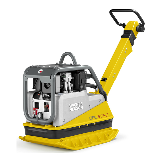
5 Construction and function Construction and function Items supplied The machine is delivered fully assembled and is ready for operation out of the box. Included in the delivery: Vibratory plate Starting crank (optional) Operator’s manual Application The vibratory plate is used for the compaction of soils and is used in gardening and landscaping, civil engineering and road and pavement construction. - Page 27 5 Construction and function The drive motor operates according to the Diesel principle, is started electrically through a gear and pinion starter, sucks combustion air through a dry air filter and is air-cooled. To facilitate the starting procedure (at very cold temperatures, with manual start) the drive motor has a decompression system.
-
Page 28: Versions
5 Construction and function Narrow protective frame (optional) For narrow cable trenches, the narrow protective frame is recommended. Versions In this operator's manual different machine types are listed: Versions Description Electric starter Operating hour meter Extension plates Compatec compaction display Narrow protective frame 100_0202_sf_0006.fm... -
Page 29: Components And Operator Controls
6 Components and operator controls Components and operator controls Components Pos. Designation Pos. Designation Engine Protective frame Upper mass Operating hour meter (optional) Base plate Extension plates (optional) Centre pole Compatec compaction display (optional) Central suspension Control lamp operation Fuel tank Nameplate Centre pole The optimum working height of the centre pole can be changed by adjusting the... -
Page 30: Operating Elements
6 Components and operator controls Operating elements Always keep displays and operating elements of the machine clean, dry and free of oil and grease. Operator's controls such as the ON/OFF switch, throttle grips etc. may not be locked, manipulated or changed without authorisation. Pos. -
Page 31: Din En Iso 9001 Certificate
6 Components and operator controls Grip for centre pole lock The grip for centre pole lock is used to release the centre pole in order to bring it into the working position. Threaded spindle The threaded spindle is used to set the optimum working height of the centre pole. -
Page 32: Transport
7 Transport Transport WARNING Improper handling may result in injury or serious material damage. Read and follow all safety instructions in this operator's manual. DANGER Danger of falling. A falling machine can cause serious injury, e.g. by crushing. Only use suitable and tested hoisting gear and lifting tackle (safety load hooks) with sufficient capacity. -
Page 33: Loading And Transport
7 Transport Loading and transport Carry out preparations Note: Wacker Neuson recommends emptying the fuel tank before transport. Pos. Designation Pos. Designation Centre pole Grip for centre pole lock During loading and transporting the centre pole must be locked by engaging the grip for the centre pole lock in a vertical centre pole position. - Page 34 7 Transport Lifting and tying down the machine Note: Designate a flagman for safe lifting. Pos. Designation Pos. Designation Central suspension Securing eyelets 1. When lifting the machine, attach suitable lifting tackle to the central suspen- sion. 2. Load machine carefully in or on a viable and safe means of transport. Pos.
-
Page 35: Use And Operation
Checks before starting Check engine and components for damage. If there is visible damage do not operate the machine and contact a Wacker Neuson dealer immediately. Ensure that loose packing material has been removed from the machine. Check the fuel supply. -
Page 36: Adjust Centre Pole
8 Use and operation 8.1.2 Adjust centre pole Pos. Designation Pos. Designation Centre pole Threaded spindle The optimum working height of the centre pole can be set by adjusting the threaded spindle. Notes on operation WARNING Danger of tipping Risk of serious injury by machine slipping or tipping. In the vicinity of edges is at least 2/3 of the machine must be on a sound surface. -
Page 37: Starting
Vibration of paving stones In the event of compaction of interlocking paving stones, Wacker Neuson recom- mends the use of the slider to prevent damage to the machine and compaction material, see the accessories chapter. -
Page 38: Starting The Machine (Manual Start)
8 Use and operation 8.3.1 Starting the machine (manual start) WARNING Starting crank can cause serious injury. Do not use a defective starting crank. Only use a clean starting crank. Pos. Designation Pos. Designation Throttle control lever Starting crank support Decompression lever 1. - Page 39 8 Use and operation 5. Grasp handle grip with one hand, with the other hand support the protective cage. Note: After engagement of the automatic decompression five turns of the start- ing crank are required until the engine can compress again and ignite. 6.
-
Page 40: Cold Starting The Machine (Manual Start)
8 Use and operation 8.3.2 Cold starting the machine (manual start) Note: The engine should rotate freely at temperatures below -5 °C. Pos. Designation Pos. Designation Decompression lever Metering device Hand lever oil pressure monitor- 1. Bring decompression lever to neutral position. 2. -
Page 41: Starting The Machine (Electric Starter)
8 Use and operation 8.3.3 Starting the machine (electric starter) Pos. Designation Pos. Designation Throttle control lever Ignition lock Decompression lever Charging indicator light 1. Set the throttle control lever to full throttle position. Note: In extreme cold also operate the decompression lever - set upwards. In this position, the decompression system engages and the engine is ready to start. - Page 42 8 Use and operation Machine with Compatec - compaction display (optional) Pos. Designation Pos. Designation Display unit LEDs / light bar indicator 1. During the first few seconds after starting the engine a light bar indicator ap- pears on the display unit. 2.
-
Page 43: Operation
8 Use and operation Operation The intended operator space is behind the machine. Hold and steer the machine using the control handle. 8.4.1 Choose travel direction Pos. Designation Pos. Designation forwards backwards 1. Set the throttle control lever to full throttle position. 2. -
Page 44: Turning Off The Machine (Manual Start)
8 Use and operation 8.5.1 Turning off the machine (manual start) Pos. Designation Throttle control lever 1. Pull back gas throttle lever to the hilt. 2. Engine stops. 8.5.2 Turning off the machine (electric starter) Pos. Designation Pos. Designation Throttle control lever Charging indicator light Ignition lock 1. -
Page 45: Maintenance
9 Maintenance Maintenance WARNING Improper handling may result in injury or serious material damage. Read and follow all safety instructions in this manual. WARNING Danger of poisoning by exhaust fumes. Exhaust fumes contain poisonous carbon monoxide, which may lead to uncon- sciousness or death. -
Page 46: Maintenance Table
9 Maintenance WARNING Risk of injury due to non-existent or non-functioning safety devices. Only operate the machine if the safety devices are properly installed and working. Do not modify or remove safety devices. Maintenance table Maintenance work daily h /Y weekly monthly... -
Page 47: Maintenance Work
Regrease threaded spindle and stop bolt pin Check starter battery fluid level* 250 h *Observe engine operator's manual ** This work is to be performed by the Wacker Neuson contact partner's service. Maintenance work CAUTION Health hazard due to fuel, lubricants and coolants. - Page 48 9 Maintenance Check fuel level and refill. Pos. Designation Fuel filler neck 1. Fold cover on side. 2. Remove any dirt around the fuel filler neck. 3. Open fuel filler neck 4. Visually check fuel level 5. If necessary, refill fuel with a clean filling vessel For fuel type see chapter Technical data.
- Page 49 9 Maintenance Check water trap Pos. Designation Pos. Designation Cover plate Hexagonal bolt 1. Remove cover plate. 2. Loosen hexagonal bolt by 2-3 turns. 3. Collect the drops which emerge in a transparent container. Note: Since water is heavier than diesel fuel, water appears first and then fuel. This is indicated by a clear dividing line.
- Page 50 9 Maintenance Screwed connections With vibration plates the screwed connections must be checked for tightness pe- riodically. Check and change V-belt and belt stabilizer Pos. Designation Pos. Designation Belt guard Screw 1. Remove V-belt guard 2. Check the condition of the V-belt and the belt stabilizer, if belt width is less than the dimension of 15.5 mm or there is visible damage, it must be changed.
- Page 51 9 Maintenance Note: By using the automatic centrifugal clutch a re-tightening of the V-belt is not required. 11. Replace and tighten the V-belt guard. Tightening torque 25 Nm. Change exciter oil and check oil level DANGER Danger of scalding Caution when draining hot oil.
- Page 52 9 Maintenance 6. Fill new oil (for exciter oil type and quantity see chapter Technical Data) in the filler boring, use appropriate and clean filling vessel. 7. Place the machine horizontally on a level surface. 8. Screw in the screw plug with sealing ring in the filler boring. Tightening torque 100 Nm.
- Page 53 Note: Only Wacker Neuson use starter batteries. Only replace defective starter batteries with Wacker Neuson starter bat- teries. See Technical Data section. Only the Wacker Neuson starter battery is vibration proof and therefore suitable for the high vibration exposure. Pos.
- Page 54 9 Maintenance 5. Place the new starter battery and insert degassing tube. Note: First connect positive terminal, then the negative terminal. 6. Connect starter battery. Pos. Designation Pos. Designation Positive terminal cover Degassing hose Coiled helix cable Note: Before installing the battery cover, ensure that the positive terminal cover is attached.
-
Page 55: 10 Troubleshooting
If all LEDs are permanently Switch-on procedure when en- Have the machine repaired.* flashing after initialisation, the gine is running. sensor has not been success- Sensor failure. fully tested. *This work is to be performed by the Wacker Neuson contact partner's service. 100_0202_ts_0008.fm... -
Page 56: Performing Jump Start With Donor Battery
10 Troubleshooting 10.2 Performing jump start with donor battery If the starter battery of the machine is discharged and the engine does not start, a jump-start with a donor battery is possible. WARNING Explosion hazard due to oxyhydrogen. Risk of injury from splashing acid. ... - Page 57 Help starting 5. Start engine. If the engine does not switch on after 15 seconds, abort start attempt and Wacker Neuson contact partner. 6. Let the engine run for several minutes. Disconnect the jumper cables 7. Disconnect the clamping pliers of the black jumper cable from the ground point of the machine.
-
Page 58: 11 Disposal
11 Disposal 11 Disposal 11.1 Disposal of batteries For customers in EU countries This device contains one or more batteries or rechargeable batteries (hereafter referred to as "batteries"). This battery is subject to the European Directive 2006/66/EC on (waste) batteries, as well as the corresponding national legisla- tion. -
Page 59: 12 Accessories
Sliders provide maximum protection against damage to the paving stone sur- face, which is required especially in surface-coated paving locations. Starting crank DPU 4545 and DPU 5545 - short tool shank of the starting crank. DPU 6555 - long tool shank of the starting crank. Starting crank bracket... -
Page 60: 13 Technical Data
13 Technical data 13 Technical data Designation Unit DPU 4545H DPU 4545He DPU 4545Heh Item no. 5100009661 5100016951 5100009659 Centrifugal force 45,00 45,00 45,00 Vibrations 1/min 4.140 4.140 4.140 Surface capacity (6.952)) (6.952)) (6.952)) Forward travel m/min 25,0 25,0 25,0 (ft/min) (82.0) (82.0) - Page 61 13 Technical data Designation Unit DPU 4545H DPU 4545He DPU 4545Heh Standard EN 500-4 Sound power level L dB(A) measured 106,1 106,1 106,1 guaranteed Standard EN 500-4, 2000/14/EG Vibration total value a Standard (ft/s (4.9) (4.9) (4.9) EN 500-4 Uncertainty of measure- ment of the vibration total (ft/s 1.6)
- Page 62 13 Technical data Designation Unit 4545Hec 4545Hech 4545Heh US 4545Hech US Item no. 5100016953 5100015429 5100009660 5100016952 Centrifugal force 45,00 45,00 45,00 45,00 Vibrations 1/min 4.140 4.140 4.140 4.140 Surface capacity (6.952)) (6.952)) (6.952)) (6.952)) Forward travel m/min 25,0 25,0 25,0 25,0 (ft/min)
- Page 63 13 Technical data Designation Unit 4545Hec 4545Hech 4545Heh US 4545Hech US Sound power level L dB(A) measured 106,1 106,1 106,1 106,1 guaranteed Standard EN 500-4, 2000/14/EG Vibration total value a Standard (ft/s (4.9) (4.9) (4.9) (4.9) EN 500-4 Uncertainty of measure- ment of the vibration total (ft/s 1.6)
-
Page 64: Combustion Engine
13 Technical data 13.1 Combustion engine Designation Unit Manufacturer Hatz Engine type 1D42S-151 1D42S-152 1D42S-177 Combustion process four-cycle four-cycle four-cycle Cooling Air cooling Air cooling Air cooling Cylinders Displacement cm³ (in³) 445 (27.2) 445 (27.2) 445 (27.2) Max. permissible lift °... - Page 65 13 Technical data Designation Unit Wacker Neuson Battery voltage – Spezial battery for vibratory plates, 12 V, 46 Ah Battery capacity (nominal – value) 100_0202_td_0015.fm...
-
Page 66: 14 Technical Data
14 Technical data 14 Technical data Designation Unit 5545H 5545He 5545Heh 5545Heap Item no. 5100009656 5100016947 5100009652 5100016949 Centrifugal force 55,00 55,00 55,00 55,00 Vibrations 1/min 4.150 4.150 4.150 4.150 Surface capacity 1,170 (7.486)) (7.486)) (7.486)) (8.938)) Forward travel m/min 27,0 27,0 27,0... - Page 67 14 Technical data Designation Unit 5545H 5545He 5545Heh 5545Heap Standard EN 500-4 dB(A) Sound power level L measured 107,1 107,1 107,1 107,1 guaranteed Standard EN 500-4, 2000/14/EG Vibration total value a Standard (ft/s (4.9) (4.9) (4.9) (4.9) EN 500-4 Uncertainty of measure- ment of the vibration total (ft/s 1.6)
- Page 68 14 Technical data Designation Unit DPU 5545 DPU 5545 DPU 5545 Hehap Hech Item no. 5100009654 5100016950 5100009655 Centrifugal force 55,00 55,00 55,00 Vibrations 1/min 4.150 4.150 4.150 Surface capacity 1.170 (8.938)) (7.486)) (7.486)) Forward travel m/min 26,0 27,0 27,0 (ft/min) (85.3) (88.6)
- Page 69 14 Technical data Designation Unit DPU 5545 DPU 5545 DPU 5545 Hehap Hech Standard EN 500-4 dB(A) Sound power level L measured 107,1 107,1 107,1 guaranteed Standard EN 500-4, 2000/14/EG Vibration total value a Standard (ft/s (4.9) (4.9) (4.9) EN 500-4 Uncertainty of measure- ment of the vibration total (ft/s...
- Page 70 14 Technical data Designation Unit DPU 5545Hech US DPU 5545Heh US Item no. 5100016948 5100009653 Centrifugal force 55,00 55,00 Vibrations 1/min 4.150 4.150 Surface capacity (7.486)) (7.486)) Forward travel m/min 27,0 27,0 (ft/min) (88.6) (88.6) Reverse travel m/min 20,0 20,0 (ft/min) (65.6) (65.6)
- Page 71 14 Technical data Designation Unit DPU 5545Hech US DPU 5545Heh US Sound power level L dB(A) measured 107,1 107,1 guaranteed Standard EN 500-4, 2000/14/EG Vibration total value a Standard (ft/s (4.9) (4.9) EN 500-4 Uncertainty of measure- ment of the vibration total (ft/s 1.6) 1.6)
-
Page 72: Combustion Engine
14 Technical data 14.1 Combustion engine Designation Unit Manufacturer Hatz Engine type 1D42S-151 1D42S-152 1D42S-177 Combustion process four-cycle four-cycle four-cycle Cooling Air cooling Air cooling Air cooling Cylinders Displacement cm³ (in³) 445 (27.2) 445 (27.2) 445 (27.2) Max. permissible lift °... - Page 73 14 Technical data Designation Unit Wacker Neuson Battery voltage – Spezial battery for vibratory plates, 12 V, 46 Ah Battery capacity (nominal – value) 100_0202_td_0016.fm...
-
Page 74: Technical Data
15 Technical data 15 Technical data Designation Unit DPU 6555 DPU 6555 DPU 6555 DPU 6555 Heap Item no. 5100009651 5100015773 5100016940 5100016943 Centrifugal force 65,00 65,00 65,00 65,00 Vibrations 1/min 4.150 4.150 4.150 4.150 Surface capacity 1.200 1.200 1.200 1.450 (9.167)) (9.167)) - Page 75 15 Technical data Designation Unit DPU 6555 DPU 6555 DPU 6555 DPU 6555 Heap Standard EN 500-4 dB(A) Sound power level L measured guaranteed Standard EN 500-4, 2000/14/EG Vibration total value a Standard (ft/s (4.9) (4.9) (4.9) (4.9) EN 500-4 Uncertainty of measure- ment of the vibration total (ft/s...
- Page 76 15 Technical data Designation Unit DPU 6555 DPU 6555 DPU 6555 6555Heh Hehap Hesh Item no. 5100009636 5100009638 5100016941 5100015774 Centrifugal force 65,00 65,00 65,00 65,00 Vibrations 1/min 4.150 4.150 4.150 4.150 Surface capacity 1.200 1.450 1.200 1.200 (9.167)) (11.077)) (9.167)) (9.167)) Forward travel...
- Page 77 15 Technical data Designation Unit DPU 6555 DPU 6555 DPU 6555 6555Heh Hehap Hesh Standard EN 500-4 dB(A) Sound power level L measured guaranteed Standard EN 500-4, 2000/14/EG Vibration total value a Standard (ft/s (4.3) (4.3) (4.3) (4.3) EN 500-4 Uncertainty of measure- ment of the vibration total (ft/s...
- Page 78 15 Technical data Designation Unit DPU 6555 DPU 6555 DPU 6555 6555Hec Hech Hecs Hecsh Item no. 5100016944 5100009639 5100016945 5100015775 Centrifugal force 65,00 65,00 65,00 65,00 Vibrations 1/min 4.150 4.150 4.150 4.150 Surface capacity 1.200 1.200 1.200 1.200 (9.167)) (9.167)) (9.167)) (9.167))
- Page 79 15 Technical data Designation Unit DPU 6555 DPU 6555 DPU 6555 6555Hec Hech Hecs Hecsh Sound power level L dB(A) measured guaranteed Standard EN 500-4, 2000/14/EG Vibration total value a Standard (ft/s (4.3) (4.3) (4.3) (4.3) EN 500-4 Uncertainty of measure- ment of the vibration total (ft/s (1.6)
- Page 80 15 Technical data Designation Unit DPU 6555 DPU 6555 DPU 6555 DPU 6555 He US Heh US Hec US Hech US Item no. 5100016942 5100009637 5100016946 5100009650 Centrifugal force 65,00 65,00 65,00 65,00 Vibrations 1/min 4.150 4.150 4.150 4.150 Surface capacity 1.200 1.200 1.200...
- Page 81 15 Technical data Designation Unit DPU 6555 DPU 6555 DPU 6555 DPU 6555 He US Heh US Hec US Hech US Sound power level L dB(A) measured guaranteed Standard EN 500-4, 2000/14/EG Vibration total value a Standard (ft/s (4.3) (4.3) (4.3) (4.3) EN 500-4...
-
Page 82: Combustion Engine
15 Technical data 15.1 Combustion engine Designation Unit Manufacturer Hatz Engine type 1D81S-248 1D81S-249 1D81S-319 Combustion process four-cycle four-cycle four-cycle Cooling Air cooling Air cooling Air cooling Cylinders Displacement cm³ (in³) 667 (40.7) 667 (40.7) 667 (40.7) Max. permissible lift °... - Page 83 15 Technical data Designation Unit Wacker Wacker Battery voltage Spezial – Spezial Neuson Neuson battery battery Battery capacity (nominal – for vibratory for vibratory value) plates, 12 V, 46 plates, 12 V, 46 100_0202_td_0017.fm...
-
Page 84: 16 Emission Control Systems Information And Warranty
16 Emission control systems information and warranty 16 Emission control systems information and warranty The Emission Control Warranty and associated information is valid only for the U.S.A., its territories, and Canada. Emission control systems warranty statement See the engine owner’s manual for the applicable exhaust and evaporative emis- sion warranty statement. -
Page 85: Ec Declaration Of Conformity
EC Declaration of Conformity Manufacturer Wacker Neuson Produktion GmbH & Co. KG, Preußenstraße 41, 80809 München Product Product DPU 4545 Product category Vibrating plate Product function Compacting soils Item number 5100009661, 5100016951, 5100009659, 5100016953, 5100015429 Net installed power 6,4 kW... -
Page 87: Ec Declaration Of Conformity
EC Declaration of Conformity Manufacturer Wacker Neuson Produktion GmbH & Co. KG, Preußenstraße 41, 80809 München Product Product DPU 5545 Product category Vibrating plate Product function Compacting soils Item number 5100009656, 5100016947, 5100009652, 5100016949, 5100009654, 5100016950, 5100009655 Net installed power... -
Page 89: Ec Declaration Of Conformity
EC Declaration of Conformity Manufacturer Wacker Neuson Produktion GmbH & Co. KG, Preußenstraße 41, 80809 München Product Product DPU 6555 Product category Vibrating plate Product function Compacting soils Item number 5100009651, 5100015773, 5100016940, 5100016943, 5100009636, 5100009638, 5100016941, 5100015774, 5100016944, 5100009639,...
Need help?
Do you have a question about the DPU 4545 and is the answer not in the manual?
Questions and answers