
Related Manuals for Wacker Neuson DPU 3050H


Summary of Contents for Wacker Neuson DPU 3050H
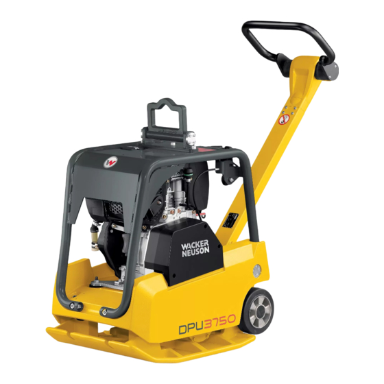
- Page 1 Operator’s Manual Vibratory Plate DPU 3050H, DPU 3750Hts 5200001077 0811...
- Page 2 Manufacturer Wacker Neuson Produktion GmbH & Co. KG Preußenstraße 41 80809 München www.wackerneuson.com Tel.: +49-(0)89-354 02-0 Fax: +49-(0)89-354 02-390 Translation of the original operator's manual in German 0217755en 05 0811...
-
Page 3: Table Of Contents
Inhalt Foreword ........................5 Introduction ....................... 6 2.1 Means of representation for this operator's manual ........... 6 2.2 Wacker Neuson representative ................7 2.3 Described machine types ................... 7 2.4 Identification of the machine................8 Safety ......................... 9 3.1 Principle......................9 3.2 Qualification of the operating personnel ............ - Page 4 Maintenance ......................36 9.1 Maintenance schedule ..................37 9.1.1 One-time maintenance after initial operation........37 9.1.2 Daily maintenance work ............... 37 9.1.3 Regular maintenance ................38 9.2 Maintenance work .................... 39 9.2.1 Cleaning machine................. 39 9.2.2 Check the air cleaner maintenance indicator ........39 9.2.3 Cleaning the air cleaner................
-
Page 5: Foreword
Foreword This operator's manual contains information and procedures for the safe opera- tion and maintenance of your Wacker Neuson machine. In the interest of your own safety and to prevent accidents, you should carefully read through the safety information, familiarize yourself with it and observe it at all times. -
Page 6: Introduction
2 Introduction Introduction Means of representation for this operator's manual Warning symbols This operator's manual contains safety information of the categories: DANGER, WARNING, CAUTION, NOTICE. They should be followed to prevent danger to life and limb of the operator or dam- age to equipment and exclude improper service. -
Page 7: Wacker Neuson Representative
This symbol is used for lists. Wacker Neuson representative Depending on your country, your Wacker Neuson representative is your Wacker Neuson service, your Wacker Neuson affiliate or your Wacker Neuson dealer. You can find the addresses in the Internet at www.wackerneuson.com. -
Page 8: Identification Of The Machine
2 Introduction Identification of the machine Nameplate data The nameplate lists information that uniquely identifies your machine. This infor- mation is needed to order spare parts and when requesting additional technical information. Enter the information of your machine into the following table: Item Designation Your information... -
Page 9: Safety
Installation of accessories which are not from Wacker Neuson. It is no problem to install spare parts from Wacker Neuson. It is no problem to install accessories that are available in the Wacker Neuson product range of your machine. Please refer to the installation regulations in this... - Page 10 Have damaged or defective components replaced immediately! For further information, refer to chapter Troubleshooting. Spare parts, accessories Use only spare parts from Wacker Neuson or such that are equivalent to the orig- inal parts in design and quality. Only use accessories from Wacker Neuson.
- Page 11 3 Safety Exclusion of liability Wacker Neuson will refuse to accept liability for injuries to persons or for damage to materials in the following cases: Structural modifications. Improper use. Failure to comply with this operator's manual. Improper handling. Using of spare parts which are not from Wacker Neuson and not equivalent to the original parts in design and quality.
-
Page 12: Qualification Of The Operating Personnel
3 Safety Checking for signs of damage Inspect the machine when it is switched off for any signs of damage at least once per work shift. Do not operate the machine if there is visible damage or defects. Have any damage or defects eliminated immediately. Qualification of the operating personnel Operator qualifications Only trained personnel are permitted to start and operate the machine. -
Page 13: Protective Gear
When wearing ear protection while working, you must pay attention and exercise caution because your hearing is limited, e.g. in case someone screams or a sig- nal tone sounds. Wacker Neuson recommends that you always wear ear protection. Transport Switching off the machine Before you transport the machine, it must be switched off, and the engine must be given sufficient time to cool down. -
Page 14: Operating Safety
3 Safety Lifting When lifting the machine, observe the following instructions: Designate a skilled person to guide you for the lifting procedure. You must be able to see or hear this person. Use only suitable and certified hoisting gear, lifting tackle and load-bearing equipment with sufficient lifting capacities. - Page 15 3 Safety Work environment Familiarize yourself with your work environment before you start work. This in- cludes e.g. the following items: Obstacles in the work and traffic area. Load-bearing capacity of the ground. The measures needed to cordon off the construction site from public traffic in particular.
-
Page 16: Safety During The Operation Of Vibratory Plates
3 Safety Switching off the machine Switch off the engine in the following situations: Before breaks. If you are not using the machine. Store the machine in such a way that it cannot tilt, fall or slip. Storage location After operation, allow the machine to cool and then store it in a sealed-off, clean and dry location protected against frost and inaccessible to children. - Page 17 You must also comply with the relevant guidelines and regulations, particularly DIN 4150-3. The foundation must also have sufficient load-bearing capacity to withstand the compaction energy. In case of doubt involve a soil mechanics specialist in the evaluation. Wacker Neuson is not liable for any structural damage.
-
Page 18: Safety During The Operation Of Combustion Engines
3 Safety Safety during the operation of combustion engines Checking for signs of damage Check the engine while switched off for leaks and cracks in the fuel line, tank and fuel cap at least once per work shift. Do not operate the machine if there is visible damage or defects. Have any damage or defects eliminated immediately. - Page 19 3 Safety Safety precautions when refueling Please observe the following safety-relevant instructions when refueling: Do not refuel near open flames. Do not smoke. Turn off the engine before refueling and allow it to cool down. Refuel in a well-ventilated environment. Wear fuel-proof protective gloves and, if there is the possibility of spraying, protective goggles and clothing.
-
Page 20: Safety During The Operation Of Hydraulic Machines
Using only a Wacker Neuson battery Use only Wacker Neuson batteries to replace defective batteries, see chapter Technical Data. Only the Wacker Neuson battery is vibration resistant and thus suitable for the high vibratory stresses. - Page 21 In particular, avoid contact with hot operating fluids. Burn and scalding haz- ard. Dispose of replaced or spilled operating fluids according to the applicable regulations for environmental protection. If operating fluids escape from the machine, cease operation of the machine and have it repaired immediately by your Wacker Neuson representative.
-
Page 22: Safety And Information Labels
3 Safety 3.10 Safety and information labels Your machine has adhesive labels containing the most important instructions and safety information. Make sure that all the labels are kept legible. Replace any missing or illegible labels. The item numbers for the labels are in the parts book. Pos. - Page 23 3 Safety Pos. Label Description Improper handling can cause serious damage to the engine. When using the integrated wheels, always turn off the engine. If the engine is running, engine lubrica- tion cannot be ensured in the transport position. There is also a danger that oil may leak out of the engine crankcase breather.
-
Page 24: Scope Of Delivery
4 Scope of delivery Scope of delivery Item Designation Item Designation Machine Parts book Operator's manual The machine is delivered fully assembled and after unpacking it is ready for op- eration. The scope of delivery includes: Machine. Operator's manual. Parts book. -
Page 25: Structure And Function
5 Structure and function Structure and function Application Use the machine only as intended, see chapter Safety, Proper use. Functional description Item Designation Item Designation Air cleaner Exciter V-belt Throttle lever Exciter Control handle Base plate Guide handle head Battery Upper mass Starter Vibration dampers... - Page 26 5 Structure and function This procedure is hydraulically controlled with the control handle (3) on the guide handle head (4). The drive motor (13) attached to the upper mass (5) powers the exciter (9). The torque is transferred non-positively by the centrifugal clutch (7) and the exciter V-belt (8).
-
Page 27: Components And Operator's Controls
6 Components and operator's controls Components and operator's controls Machine Item Designation Item Designation Central suspension Integrated driving mechanism Fuel tank Guide handle Battery Control handle Recoil starter Throttle lever Electronic starter... - Page 28 6 Components and operator's controls Electronic starter (only certain machine types) Item Designation Item Designation Operation control lamp Oil pressure control lamp Charging control lamp Ignition lock...
-
Page 29: Transport
7 Transport Transport WARNING Improper handling can result in injury or serious material damage. Read and follow all safety instructions of this operator's manual, see chapter Safety. WARNING Danger due to the machine falling. If the machine falls, it can cause severe injury such as crushing. Only use suitable and tested hoisting gear and lifting tackle (safety load hooks) of sufficient lifting capacity. -
Page 30: Transporting The Machine
7 Transport Transporting the machine Item Designation Item Designation Guide handle Tie-down lugs (protective frame) Central suspension (attachment point) 1. Place the machine upright on a flat surface. 2. Switch off the engine. 3. Vertically set guide handle head and lock into place. 4. -
Page 31: Use And Operation
8 Use and operation Use and operation WARNING Improper handling can result in injury or serious material damage. Read and follow all safety instructions of this operator's manual, see chapter Safety. Prior to starting the machine 8.1.1 Checks before startup Before you start the engine, check the following: Fuel level. -
Page 32: Starting Up
8 Use and operation Starting up 8.2.1 Starting the engine with recoil starter Item Designation Throttle lever Recoil starter Note: Do not start the engine until you are sure that it is vertically stable. 1. Set throttle lever to position 1. 2. -
Page 33: Starting The Engine With Electronic Starter
8 Use and operation 8.2.2 Starting the engine with electronic starter Item Designation Ignition lock 1. Set throttle lever to position 1. 2. Insert the key into the ignition lock. 3. Turn key to position II and release when the engine has started. Note: Abort the start attempt after no more than 15 seconds. -
Page 34: Operating The Machine
8 Use and operation Operating the machine 8.3.1 Operating in the forward and reverse direction Press the control handle in the direction of travel. Note: The forward and reverse speed can be continuously varied. 8.3.2 Compacting on a slope Compacting on slopes The following points must be observed if you plan to compact inclined surfaces (slopes, escarpments): Always stand above the machine on a slope. -
Page 35: Decomissioning
8 Use and operation Decomissioning Item Designation Off switch Ignition lock Turning off the engine 1. Set throttle lever to position 0. 2. Press the OFF switch. Only for machine types with electronic starter: 3. Turn key to position 0. 4. -
Page 36: Maintenance
9 Maintenance Maintenance WARNING Improper handling can result in injury or serious material damage. Read and follow all safety instructions of this operator's manual, see chapter Safety. WARNING Injury may be caused by uncontrolled startup and moving parts. Carry out maintenance work only when the engine is off. WARNING Danger of poisoning by exhaust fumes. -
Page 37: Maintenance Schedule
Change engine oil. Check the valve clearance, set to 0.10 mm when the en- gine is cold. * * Have these tasks carried out by the service department of your Wacker Neuson con- tact person. 9.1.2 Daily maintenance work Maintenance work... -
Page 38: Regular Maintenance
Check the valve clearance, set to 0.10 mm when the engine is cold. * Replace the fuel filter. * Replace air cleaner. Clean oil filter. * * Have these tasks carried out by the service department of your Wacker Neuson contact person. -
Page 39: Maintenance Work
9 Maintenance Maintenance work 9.2.1 Cleaning machine WARNING Use of improper cleaning agents may lead to fire or explosion. Do not use gasoline or any other solvents to clean components. Clean the machine with water after each use. High pressure washers or chemical agents must not be used. 9.2.2 Check the air cleaner maintenance indicator Rev the engine briefly to its maximum speed. -
Page 40: Cleaning The Air Cleaner
9 Maintenance 9.2.3 Cleaning the air cleaner Note: If the motor starts smoking and if the motor output drops at the same time, this indicates that the filter is clogged. 1. Place the machine upright on a flat surface. 2. Switch off the engine. 3. -
Page 41: Checking The Water Separator
9 Maintenance 9.2.4 Checking the water separator Item Designation Inspection glass Drain plug 1. Place the machine upright on a flat surface. 2. Switch off the engine. 3. Check whether there is water in the inspection glass of the water separator. 4. -
Page 42: Checking Engine Oil Level
9 Maintenance 9.2.5 Checking engine oil level Item Designation Oil level dipstick Mark 1. Place the machine upright on a flat surface. 2. Switch off the engine. 3. Remove any dirt around the oil level dipstick. 4. Remove the oil level dipstick and wipe it with a clean, lint-free cloth. 5. -
Page 43: Changing The Engine Oil
9 Maintenance 9.2.6 Changing the engine oil Item Designation Item Designation Oil level dipstick Oil drain hose Oil change valve Note: The work area should be covered with a waterproof sheet to protect the floor (protection of the environment). Note: Drain the oil while the engine is still hot. -
Page 44: Checking / Filling Hydraulic Oil Level
9 Maintenance 9.2.7 Checking / filling hydraulic oil level Item Designation Item Designation Filler hole Control handle Gear Guide handle 1. Place the machine upright on a flat surface. 2. Switch off the engine. 3. Let machine cool off. 4. Vertically set guide handle head and lock into place. 5. -
Page 45: Checking Exciter Oil Level
9 Maintenance 9.2.8 Checking exciter oil level Item Designation Filler hole Start of thread 1. Place the machine upright on a flat surface. 2. Switch off the engine. 3. Let machine cool off. 4. Remove any dirt around the filler hole. WARNING Hot exciter oil can spill, causing scalding injuries. - Page 46 9 Maintenance 8. Close filler hole and use a torque wrench to tighten it to 100 Nm.
-
Page 47: Re-Tighten Exciter V-Belt
9 Maintenance 9.2.9 Re-tighten exciter V-belt Item Designation Item Designation V-belt Screws (3 pieces) Engine V-belt disc Belt guard Disc Screws (3 pieces) V-belt pulley half 1. Place the machine upright on a flat surface. 2. Switch off the engine. 3. - Page 48 9 Maintenance 11. If necessary retighten the screws.
-
Page 49: 10 Malfunctions
Have the machine repaired. * go out. Controller defective. Oil control lamp does not go Motor oil level is too low. Top up with engine oil. out. * Have these tasks carried out by the service department of your Wacker Neuson contact person. -
Page 50: Boost
10 Malfunctions 10.1 Boost WARNING Danger of explosion due to detonating gas. Injury may result from spraying acid. Wear safety glasses and acid-proof protective gloves. The donor battery and the machine's battery must have the same voltage (12 V). Avoid short circuit due to voltage reversal (positive to positive, negative to negative). - Page 51 10 Malfunctions 6. Follow these steps in reverse to remove all clamped on cables - first the black and then the red booster cable.
-
Page 52: 11 Disposal
11 Disposal 11 Disposal 11.1 Disposal of batteries For customers in EU countries This device contains one or more batteries or rechargeable batteries (hereafter referred to as "batteries"). This battery is subject to the European Directive 2006/66/EC on (waste) batteries, as well as the corresponding national legisla- tion. -
Page 53: 12 Accessories
12 Accessories 12 Accessories There is a wide range of accessories available for the machine. For more information on the individual accessories, visit the following website: www.wackerneuson.com. -
Page 54: 13 Technical Data
13 Technical data 13 Technical data Machine Designation Unit DPU 2540H DPU 2550H DPU 2560H DPU 2560Hts Item no. 0610035 0610036 0610037 0610038 Length x width x height mm (ft) 733 x 400 x 733 x 500 x 733 x 600 x 1,170 (guide handle in transport 1,170 1,170 (2.4 x... - Page 55 13 Technical data Designation Unit DPU 3050H DPU 3050He DPU 3060H DPU 3060Hts Item no. 0610039, 0610298 0610040 0610042 5100000310 Length x width x height mm (ft) 733 x 500 x 1,170 733 x 600 x 1,170 (guide handle in transport (2.4 x 1.6 x 3.8)
- Page 56 13 Technical data Designation Unit DPU 3060Hets DPU 3070H Item no. 0610302 0610041 Length x width x height 733 x 600 x 1,170 733 x 700 x 1,170 (guide handle in transport (ft) (2.4 x 1.9 x 3.8) (2.4 x 2.3 x 38) position) Operating weight kg (lb)
- Page 57 13 Technical data Designation Unit 3750Hts 3750Hets 3760Hts 3760Hets Item no. 0610321, 0610322 0610358 0610359 5100000311 Length x width x height mm (ft) 733 x 500 x 1,170 733 x 600 x 1,170 (guide handle in transport (2.4 x 1.6 x 3.8) (2.4 x 1.9 x 3.8) position) Operating weight...
- Page 58 13 Technical data Drive motor Designation Unit DPU 25.. DPU 30.. DPU 37.. Manufacturer HATZ Type 1B20 1B30 Engine displacement cm³ (in³) 243 (14.8) 347 (21.2) Rated output* Operating power Operating blade speed 2,800 Diesel according to DIN EN 590 Fuel type Fuel consumption l/h (qt/h)
- Page 59 13 Technical data Electrical Designation Unit DPU 3050He, DPU 3060Hets, DPU 3750Hets, DPU 3760Hets Battery type Special Wacker Neuson battery for vibration plates, 12 V - 18 Ah, maintenance free...
- Page 60 13 Technical data...
-
Page 61: Ec Declaration Of Conformity
EC Declaration of Conformity Manufacturer Wacker Neuson Produktion GmbH & Co. KG, Preußenstraße 41, 80809 München Product Product DPU 25.. DPU 30.. DPU 37.. Product category Vibrating plate Product function Compacting soils Item number 0610035, 0610036, 0610039, 0610298, 0610321, 0610322,... - Page 64 Tel. : (262) 255-0500 Fax: (262) 255-0550 Tel.: (800) 770-0957 Wacker Neuson Limited - Room 1701–03 & 1717–20, 17/F. Tower 1, Grand Century Place, 193 Prince Edward Road West, Mongkok, Kowloon, Hongkong. Tel: (852) 3605 5360, Fax: (852) 2758 0032...
Need help?
Do you have a question about the DPU 3050H and is the answer not in the manual?
Questions and answers