
Related Manuals for Wacker Neuson DPU 6055


Summary of Contents for Wacker Neuson DPU 6055
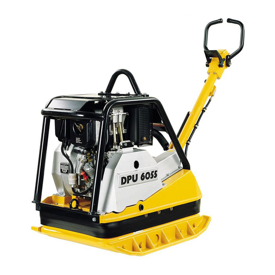
- Page 1 VIBRATORY PLATE DPU 6055 0200303en - 12.2001 0008766 100 0008768 100 Operator´s Manual...
-
Page 3: H00553Gb
CONTENTS Type Item no. DPU 6055 0008766 ... DPU 6055 - 860 wide 0008768 ... This machine has been equipped with an EPA certified engine. Additional information can be found in the engine manufacturers notes. H00553GB... -
Page 5: Foreword
FOREWORD Foreword For your own safety and protection from bodily injuries, carefully read, understand and follow the safety instruc- tions in this manual. Please operate and maintain your Wacker machine in accordance with the instructions in this manual. Your Wacker machine will reward your attention by giving trouble-free operation and a high degree of availability. Defective machine parts are to be replaced as soon as possible. -
Page 6: Table Of Contents
TABLE OF CONTENTS FOREWORD SAFETY INSTRUCTIONS General instructions Operation Safety checks Maintenance Transport Maintenance checks TECHNICAL DATA DESCRIPTION Field of application Dimensions Max. admissible inclination Description of function TRANSPORT TO WORK SITE, RECOMMENDATIONS ON COMPACTION Transport to work site Recommendations on compaction OPERATION Starting requirements Electric start... - Page 7 TABLE OF CONTENTS EC - CONFORMITY-CERTIFICATE 0127308GBIVZ.GB.fm...
-
Page 8: Safety Instructions
SAFETY INSTRUCTIONS SAFETY INSTRUCTIONS FOR THE USE OF VIBRATORY PLATES WITH COMBUSTION ENGINES General instructions Vibratory plates may only be operated by persons who * are at least 18 years of age * are physically and mentally fit for this job * have been instructed in guiding vibratory plates and proved their ability for the job to the employer * may be expected to carry out the job they are charged with carefully. -
Page 9: Safety Checks
SAFETY INSTRUCTIONS Make sure the soil or subsoil to be compacted has a high enough load carrying capacity. Use appropriate protective clothing while working or while carrying out maintenance work. When traveling backwards the operator has to guide the vibration plate laterally by its guide handle so that he will not be squeezed between the handle and a possible obstacle. -
Page 10: Technical Data
TECHNICAL DATA DPU 6055 DPU 6055 - 860 wide Item no. 0008766 ... 0008768 ... Operating weight without extension plates (550) with extension plates narrow (610) with extension plates Serial (710) with extension plates wide (860) Power transmission From drive engine directly to exciter... - Page 11 TECHNICAL DATA The required sound specifications, called-for by the EC-Machine Regulations per Appendix 1, Paragraph 1.7.4.f, are - sound pressure level at the operator's location L = 97 dB(A) The sound values were determined according to ISO 3744 for the sound power level (L ) and, alternately, ISO 6081 for the sound pressure level (L ) at the operator's location.
-
Page 12: Description
DESCRIPTION Field of application The vibratory plate has been designed for the compaction of almost every type of soil, both in trenches as well as surface compaction. In addition, it is possible to vibrate paving stones an concrete blocks by using extension plates up to 86 cm (accessories). -
Page 13: Description Of Function
DESCRIPTION Description of function The vibration required for compaction is produced by the exciter (13) which is firmly joined to the lower mass (5). This exciter (13) is designed as a central vibrator with aligned vibrations. Such a principle permits the di- rection of vibration to be changed by turning the eccentric weights (15). - Page 14 DESCRIPTION The speed of the drive engine (1) can be infinitely varied by remote control on the throttle control lever (8). The upper (4) and lower (5) masses are connected to each other by 4 vibration-damping rubber metal shock mounts (14). This damping system prevents the very high frequencies from being transmitted to the upper mass (4).
-
Page 15: Transport To Work Site, Recommendations On Compaction
TRANSPORT TO WORK SITE, RECOMMENDATIONS ON COMPACTION Transport to work site Conditions: To transport the vibration plate, only use suitable lifting equipment with a minimum load-bearing capacity of 500 kg. Always switch off engine before transporting the machine! Only attach suitable tackle at the central lifting point (16) provided. The central lifting point is located exactly above the centre of gravity of the machine. -
Page 16: Operation
OPERATION Starting requirements 1. Engine oil Check oil level on oil dipstick (19), if necessary top up with HD brand oil SAE 10 W-40 using the filler nozzle (21). ATTENTION! The machine must be level and the engine stopped before proceeding with the oil level check. - Page 17 T00796GB...
-
Page 18: Electric Start
OPERATION Electric start 1. Turn the throttle control lever (8) clockwise into load position 1/2 - 3/4. 2. Leave decompression lever (2) in the position „e“. 3. Put the ignition key into ignition switch (25) and turn it clockwise into operating position (the charge control lamp (27) lights up and the buzzer will be heard). - Page 19 T00796GB...
-
Page 20: Starting The Engine With The Safety Starting Crank
OPERATION Starting the engine with the safety starting crank 1. Turn the throttle control lever to the load position 1/2 - 3/4. 2. Turn the decompression lever (2) all the way to „f“. At this point automatic decompression lever engages with an audible click, and the engine is ready to start. 3. - Page 21 T00796GB...
- Page 22 OPERATION - Slowly turn the safety starting crank counter-clockwise until the ratchet engages. Then start turning the handle with force and with ever increasing speed. The highest possible turning speed must have been reached when the decompression lever reaches position ”e” (compression). Pull the safety start crank out of the protective hood once the engine has started.
-
Page 23: Starting In Cold Weather
OPERATION Starting in cold weather Always free the engine if the temperature is less than -5 ˚C (23 ˚F). 1. Push the throttle lever (8) to the full throttle position. 2. Turn decompression lever to any position in front of starting position „f“. 3. - Page 24 T00796GB...
-
Page 25: Starting With External Battery Etc
OPERATION Starting with external battery etc. Observe the following connection sequence when using an external battery to start the engine: 1. Connect one end of jumper cable to positive terminal of auxiliary battery. 2. Connect the other end of jumper cable to positive terminal of the vibro plate battery. 3. -
Page 26: Compaction Without Extension Plates
OPERATION Compaction without extension plates If the vibration plates is used without extension plates, screw set of protective screws (8 pes) No. 0067519 into the threaded boreholes situated in the lower mass, in order to avoid threads from being damaged. Stopping the engine ATTENTION! Never switch off the engine with the automatic decompression (2) as this inevitably results in damage to the valve drive and decompression mechanism. -
Page 27: Maintenance
MAINTENANCE Maintenance schedule Component Maintenance work Maintenance interval External hardware Check for tightness. approx. 8 hours after initial start-up Drive engine First oil change and filter. 25 hours after initial start-up Machine cpl. Run a visual check to see that everything is daily complete and undamaged. -
Page 28: Engine Oil And Oil Filter
MAINTENANCE Engine oil and oil filter Check oil level: Remove dirt from the oil dip stick area. Check oil level on oil dipstick (19). ATTENTION! Place the machine in an horizontal (level) position and stop the engine before checking the oil level. If the oil level is too low, top up with HD brand oil SAE 10W-40 though the filler nozzle (21). - Page 29 T00797GB...
-
Page 30: Air Filter
MAINTENANCE Air filter Air filter inspection: Check and, if necessary, remove coarse dirt accumulation such as leaves, dust deposits etc. from air admission holes. Examine and, if necessary, clean dust outlet (l) openings of cyclone prefilter. Air filter service indicator: Start engine and push throttle to full rpm’s for a few seconds. The filter system must be cleaned if the bellows contracts and covers the green ring (m). - Page 31 T00797GB...
-
Page 32: Fuel System
MAINTENANCE Fuel system ATTENTION! Do not work close to an open fire and do not smoke when working on the fuel system. Water separator inspection: Turn hex screw „v“ 2 - 3 turns to detach. Collect the emerging drops in a transparent container. First water and then fuel drops will emerge, as water is specifically heavier than diesel fuel. -
Page 33: Battery
MAINTENANCE Battery Check acid level: 1. Remove battery cover. 2. Check acid level, if necessary top up with distilled water. 3. Secure battery cover. ATTENTION! Before mounting the battery cover, make sure that the positive terminal cover is there! Check the course of the degassing hose. ATTENTION! Protect hands end eyes against the acid! Note:... -
Page 34: Exciter
MAINTENANCE Exciter Check oil level: 1. Position vibration plate horizontally. 2. Open filler bore (40). 3. The oil level must reach the start of the thread of the filler bore (40). 4. If necessary, pour in HD brand oil SAE 10W-40 through filler bore (40) (use funnel 0,75 l). 5. -
Page 35: Faults
FAULTS Forward speed too low Cause: - To little hydraulic oil in the centre pole head. - Air in hydraulic control. Remedy: - Top up hydraulic oil. - Bleed system. Reverse speed too low Cause: - Too much oil in centre pole head. Remedy: - Correct oil level in accordance with mark. -
Page 36: Accessories
ACCESSORIES Accessories Part No. Set of blanking bolts for use without extension plates 0067519 Set of extension plates narrow (610 wide) 0126290 Set of extension plates Serial (710 wide) 0045201 Set of extension plates wide (860 wide) 0043246 Fastening set for safety starting crank 0126699 Safety starting crank 0095187... - Page 39 Wacker-Werke GmbH & Co. KG , Preußenstraße 41, 80809 München hereby certify that the construction equipment specified hereunder: 1. Category: Vibratory plate 2. Type: DPU 6055 3. Equipment item number: 0008766 ... / 0008768 ... 4. absolute installed power: 9,7 kW...
- Page 41 DIN EN ISO 9001 Certificate...
Need help?
Do you have a question about the DPU 6055 and is the answer not in the manual?
Questions and answers
How do you adjust the v belt on a dpu 6055
The V-belt on a Wacker Neuson DPU 6055 does not need to be retightened because it uses an automatic centrifugal clutch. However, if the V-belt width falls below 15.5 mm, it must be replaced. To change the exciter V-belt:
1. Remove the belt guard.
2. Undo the specified screw.
3. Remove the button, belleville spring, seal, and the front segment of the V-belt pulley.
4. Replace the exciter V-belt.
5. Reassemble the components in reverse order, ensuring the colored marking on the pin aligns with the marking on the V-belt pulley.
Do not oil or grease clutch components, as it can damage the graphite bushes.
This answer is automatically generated
I haven't a manual