Table of Contents

Related Manuals for Kranzle therm 895 ST


Summary of Contents for Kranzle therm 895 ST
- Page 1 Operating manual - EN - H i g h - p r e s s u r e c l e a n e r therm 895 ST therm 1165 ST Read and conform safety instructions before use! Keep instructions in a safe place for later use and pass them on to any future user.
-
Page 3: Table Of Contents
Contents Page Contents ......................... 3 Overview “This is what you have purchased” ................4 Description of appliance ......................5 Technical data ......................... 6 General rules - accident prevention ..................7 Safety precautions ........................8 That‘s what you have to observe ..................10 Kränzle- technology ...................... -
Page 4: Overview "This Is What You Have Purchased
This is what you have purchased Kränzle hot water high-pressure cleaners therm 895 St, therm 1165 ST 10 m steel- weave high-pressure hose DN 8 Safety trigger gun with insulated handle and screw connection Spray lance Operating manual... -
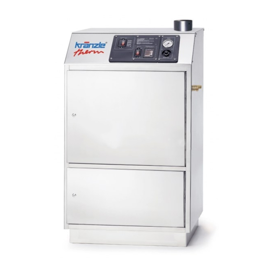
Page 5: Description Of Appliance
Description of appliance Kränzle therm 895 ST, 1165 ST Operating panel front door of housing 1 , lockable High-pressure outlet Water inlet with filter front door of housing 2, lockable Housing made of stainless steel Electric cable, 3 m (without plug) -
Page 6: Technical Data
Tecnical data therm 895 ST therm 1165 ST Operating pressure, continuously adjust. 30 - 195 bar / 3 - 19.5 MPa 30 - 165 bar / 3 - 16.5 MPa Admissible overpressure 215 bar / 21,5 MPa 180 bar / 18 MPa Water output Qmax 14.9 l/min (895 l/h) -
Page 7: General Rules - Accident Prevention
General rules Range of application This machine may only be used for cleaning facades, vehicles, containers, pavement slabs, stables, machines and smilar objects. Inspections The machine must be inspected according to the “Guidelines for Liquid Spray Devices” at least once every 12 months by a qualified person, to ensure that continued safe operation is guaranteed. -
Page 8: Safety Precautions
Safety notes Never operate the machine without supervision. The machine may only be operated by persons who have been instructed accordingly. Some parts inside the machine, all water conducting components and all metal parts of gun and lance are hot during hot water operation. Keep all hoods and protective covers closed during operation and never touch any metal parts of gun or lance. - Page 9 Never direct the water jet at people or animals! Only use power cables which are in perfect working order! Do not damage the power cable or repair it incorrectly! Never pull the high-pressure hose if it has formed kinks or “nooses”! Never pull the hose over sharp edges! Never allow children or untrained persons to use the high-pressure...
-
Page 10: That's What You Have To Observe
Please note - important! Lack of water Lack of water occurs more often than you probably believe. The more powerful a high- pressure cleaner is the greater is the danger that a lack of water occurs. If there is only an insufficient amount of water available, cavitation arises inside the pump, which is normally noticed too late or even not at all. -
Page 11: Electrical Connection
Connected load: Kränzle therm 895 ST: 400 V, 50 Hz (direction of rotation of no importance) Kränzle therm 1165 ST: 400 V, 50 Hz (direction of rotation of no importance) Check the line fusing and have the voltage and the available current intensity checked by an expert in case of uncertainty. -
Page 12: Kränzle Technology
Kränzle technology Water and Cleaning System The water is fed to the high-pressure cleaner under pressure (2-8 bar pre-pressure). A float valve regulates the water flow in the storage tank. Then the water is sucked directly from the storage tank by the high-pressure pump and forced with the adusted pressure through the heat exchanger to the safety spray lance. -
Page 13: High-Pressure Hose And Spraying Device
High-pressure hose and spraying device The high-pressure hose and spraying device supplied with the machine are made of high grade material, they are also optimized for the machine and marked as required by the appropriate regulations. If replacement parts are required, only such parts that are authorized by the manufacturer and which bear the markings required by the appropriate regulations may be used. -
Page 14: Thermostat
Kränzle technology Thermostat The thermostat controls the spray water temperature. After you switch on the device, “888” ap- pears in both displays for approx. 1 second as a test of the functioning of the displays. The thermostat also monitors the mini- mum fuel level in the tank with a floating switch. - Page 15 Thermostat - percentage mode The innovative new percent mode now lets the user specify the switching duration of the heater in percent using the “+” and “-” buttons (Pos. 5+6) (100% being the max. temperature) rather than setting the desired temperature. Now the result of the setting must be checked by using the “Actual”...
-
Page 16: Heat Exchanger
Kränzle technology Heat exchanger The water is forced through a heating coil by the high pressure pump. Heating coil: 38 m long - Content: 5 l of water - Heating capacity: max. 90 kW The fuel pump draws the oil from the tank through a filter and pumps it to the injector nozzle. -
Page 17: Fuel System
Fuel System: Your fuel may contain particles of dirt, or impurities or water may get into the tank during refuelling. To protect the fuel pump the machine is equipped with a fuel filter. Check this filter regularly for impurities and clean if necessary. Check the tank for impurities on a regular basis. -
Page 18: Commissioning
Commissioning Connect to power circuit. Make sure that the main switch is in the „OFF“ position. Connect machine to water mains (2 - 8 bar pre-pressure). Inside diameter of hose mini- mum 1/2“. The water storage tank is filled with water. The float valve shuts the water intake as soon as the tank is full. -
Page 19: Usage As Cold Water High Pressure Cleaner
Usage as cold water high-pressure cleaner Ignition switch to -OFF- position Detergent valve must be closed! (Turn knob to extreme left position „close“) Switch on main switch with disen gaged spray gun. Vent high-pressure cleaner: Pull and release trigger of spray gun various times. -
Page 20: Suction Of Detergents
Suction of detergents With detergent supply from the suction side: Detergent injectiors on the pressur side, as you probably know from other HP cleaners, consume approx. 30 % of the cleaning energy, no matter if they are used or not. Due to the water tank fitted to the Kränzle therm cleaners it is now possible to directly suck the deter- gent into the pump thus reducing output loss and increasing the efficency considerably. -
Page 21: Decommissioning - Frost Protection
Decommissioning - frost protection 01. Switch off the machine - main switch to „0“- position 02. Cut off the water supply 03. Open the spray gun briefly until the pressure is released 04. Apply the gun 05. Remove the water hose and spray gun 06. -
Page 22: Care And Maintenance (Weekly/Yearly)
Care and Maintenance The machine must be disconnected from the power supply when ser- vicing work is being carried out. The main switch should be in positi- on „0“ and the plug out of the socket. Weekly, or after approx. 40 hours of operation: Check the oil level of the high pressure pump. -
Page 23: Decalcifying The Heating Coil
Decalcifying the heating coil: Calcified machines use an unnecessary amount of energy because the water can only be heated slowly and the excess pressure valve feeds a part of the water back into the pump circuit. Calcified machines can be recognised by increased pipeline resistance. Check pipeline resistance by disconnecting the high pressure lance from the gun and switching the machine on. -
Page 24: Particular Rules, Directives And Inspections
Particular rules, directives and inspections Inspections performed by Kränzle - measurement of earth line resistance - measurement of voltage and current - inspection of tension consistency with +/- 1530 V - pressure check of heating coil at 300 bar - visual and functional check as per the inspection sheet provided - exhaust fume analysis (see test strips provided) Guidelines for liquid sprayers The machine conforms with the „Guidelines for liquid sprayers“. -
Page 25: Pipeline Plan
Pipeline plan High pressure connection Detergent Water inlet Safety valve number 5 must be set approx. 15 % higher than the unloader valve on the HP pump. Float valve, water inlet Water tank Control valve detergent High-pressure pump with integrated unloader valve Flow-Safety-Block with integrated safety valve for heating coil and flow monitoring device By-Pass line... -
Page 26: Circuit Diagram
Circuit diagram 400 V, 50 Hz... -
Page 28: Troubleshooting
Troubleshooting Malfunction Cause of malfunction / remedy Water supply Water tank runs over. Float valve is dirty or defective. Water tank does not fill completely. Float valve is defective. Water filter is dirty. Insufficient water inlet quantity. Pump does not suck. Valves stick or are dirty. -
Page 29: Excess Temperature Release
Troubleshooting Displayed malfunctions Display as follows Cause Action TARGET ACTUAL Water temperature at heating Operate appliance without chamber outlet above 147 °C heating „Heating OFF“ until the temperature has dropped below 147°C. Switch main switch „OFF“ and then back „ON“ again Appliance has not been Switch main switch „OFF“... -
Page 30: Hot Water Mode
Troubleshooting Hot water mode The fuel manometer shows the fuel pressure. If no pressure is shown, check if - there is heating oil in the tank. - the fuse in the electric box (below the operating panel) for the motor has blown. - the fuel sieve or the fuel sieve in the pump is dirty. - Page 31 Troubleshooting Malfunction Cause of malfunction / remedy Heating (burner) Fuel pump/blower operates, but Set water temperature is reached. Increase burner does not heat. temperature on thermostat with rotary control switch. Open gun, until temperature drops. Fuel tank is empty. Fuel filter is dirty. Fuel nozzle is dirty. Fuel pump/blower does not operate.
-
Page 32: Small Repairs Do It Yourself
Small repairs do it yourself! No water from the nozzle but the gauge shows full pressure: Most likely the nozzle is blocked. (Inside the pressure gauge there is no water but a filling with glycol to damp the vibration of the pointer.) Proceeding: Switch off the cleaner. - Page 33 The pressure gauge shows full pressure although the gun has been closed. The pressure switch valve switches constantly. Possible cause no.1: Leakage Having closed th gun, the HP cleaner must shut down and the pressure gauge must show „0“ bar. If the pressure gauge still shows full pressu- re and the motor constantly switches on and off, the possible reason for this can be a leakage of the pump, the HP hose or the lance.
-
Page 34: Spare Part Lists
Spare parts list... -
Page 35: Water Supply
Kränzle therm 895 ST, 1165 ST - housing Description Qty. Ord.-No Seitenblech links 47.111 Deckel 47.113 Rückwand 47.114 Seitenblech rechts 47.112 Frontblech 47.115 Wetterschutzgitter 47.100 2 Blindstopfen M20 x 1,5 Kreuzschlitzschraube M4 x 10 43.470 Zahnscheibe Ø 4,3 mm 43.471 Mutter M4 (niedrige Bauform) 40.111... -
Page 36: Electronics Switchbox
Spare parts list 33 32... - Page 37 Kränzle therm ST combustion chamber Description Qty. Ord.-No Ringmutter M 8 DIN 582 44.115 Federring A 8 44.222 Edelstahlmutter M 8 14.127 2 Brennstoffleitung „Düsenstock“ 115mm 44.089 1 Winkelverschraubung 6L x 6L 44.106 Brennstoffleitung Pumpe 44.108 1 Edelstahlschraube M 6 x 10 44.177 Blechschraube 6,3 x 13 44.109...
-
Page 38: Fuel Supply
Spare parts list... - Page 39 Kränzle therm ST comubstion chamber Description Qty. Ord.-No Außenmantel mit Grundplatte 44.379 Deckel Düsenstock 44.079 Innenmantel mit Bodenplatte 44.378 Innendeckel mit Flammrohr 44.377 Außendeckel 44.066 Brennstoffdüse 60° B 1,50 gph bei 895-1 44.077 Brennstoffdüse 60° B 1,65 gph bei 1165-1 / 1525-1 44.077 3 Blockelektrode 44.080...
-
Page 40: Combustion Chamber
Spare parts list... - Page 41 Kränzle therm ST fuel supply Description Qty. Ord.-No Deckel Brennstoffversorgung 44.011 Flansch mit Brennstoffleitungen 44.010 1 Gummidichtung 44.012 PA-Schlauch DN6 0,22 m 44.403 Schwimmerschalter 44.014 PA-Schlauch DN6 0,84 m 44.403 Steckverbinderwinkel 1/4“ x 6 44.405 Schraube 5,0 x 25 41.414 1 Steckverbinderstutzen 1/8“...
-
Page 42: Combustion Chamber Ii
Spare parts list 50 59 22 21 20 Verschlussschraube 14.113 Kabel 3 x 1,0mm² 0,49m 44.131 1 Steuerkolben kpl. mit Handrad 44.209 Rep. Satz Druckschaltermechanik Druckschalter ohne Mechanik 44.389 Druckschalter schwarz komplett 12.632... - Page 43 Kränzle therm ST unloader and pressure switch Description Qty. Ord.-No Ventilgehäuse AM-Pumpe 40.451 O-Ring 15 x 2 41.716 Ventile für APG-Pumpe 41.715 1 O-Ring 15 x 2 13.150 Einschraubwinkel 1/4“ IG x 1/4“ AG Verbindungsstück 1/8“ IG x 1/8“ IG Dichtring 40.019 Nippel...
-
Page 44: Flow Monitoring Device - Safety Block (Flow-Safety-Block)
Spare parts list - Valve housing Description Qty. Ord.-No. Dichtring 17 x 22 x 1,5 (Kupfer) 40.019 Stopfen 3/8“ 40.018 Ansaugschlauch mit Nippel R 1/4“ 44.096 4 Dichtstopfen M10 x 1 43.043 Dichtstopfen M8 x 1 13.158 Sicherungsring 40.032 Innensechskantschraube M12 x 45 40.504 Ausgangsteil Pumpe R 1/4“... - Page 45 Spare parts list - drive Description Qty. Ord.-No. Ölgehäuse 40.501 Innensechskantschraube M 8 x 30 41.036 1 Sicherungsscheibe 40.054 Flachdichtung 40.511 Öldichtung 20 x 30 x 7 40.044 1 Axial-Zylinderrollenlager AQ-Pumpe 40.524 Taumelscheibe 9,5° bei 895 40.523-9,5 11.1 Taumelscheibe 12° bei 1165 40.523-12,0 Plungerfeder 40.506...
-
Page 46: Motor Bearing
Spare parts list - engine 10 11 4 20 Description Qty. Ord.-No. Stator BG100 2,3kW 230V / 50Hz 40.720 Stator BG100 4,8kW 400V 7 50Hz 40.710 A-Lager Flansch 40.700 Rotor BG100 230V / 50Hz 40.703 1 Rotor BG 100 400V / 50Hz 40.703 Lüfterrad BG100 40.702... -
Page 47: Pump
Spare parts list - water filter Description Qty. Ord.-No. Filtergrundkörper 13.301 Filterbecher 13.302 Siebkörper 13.304 Gummidichtung 13.303 Gummidichtung 3/4“ 41.047 1 Eingangsteil beids. 3/4“ AG 13.305 Anschlussteil 13.306 O-Ring 14 x 2 43.445 Tülle 13.307 O-Ring 13 x 2,6 13.272 Überwurfmutter 41.047 5 Filter komplett... -
Page 48: Motor
Spare parts list (Setting must be 15% higher than operating pressure) - Page 49 Kränzle therm ST - Flow-Safety-Block Description Qty. Ord.-No Ventilkörper FSB250-1 14.215 Dichtstopfen M 8 x 1 13.158 Ermetoverschraubung R 3/8“ x 12 mm Rohrstutzen 1 44.365 Ermetowinkel R 1/4“ x 6L 44.062 Spannstift 14.148 Steuerkolben 14.110 O-Ring 16 x 2,0 13.150 Kolbenführung 14.130...
-
Page 50: Unloader And Pressure Switch
Spare parts list - console Description Qty. Ord.-No. Frontplatte Elektrik 891 44.042 Frontplatte Manometer 44.043 Bedienteil 44.257 Manometer 601 – 871 250bar 15.039 1 Manometer 891 400bar 15.039 4 Schraube M 5 x 14 40.536 Unterlegscheibe Ø 5,3 mm 40.135 Mutter M 5 44.113 1 Sicherungsmutter M 4... - Page 51 Spare parts list - console Description Qty. Ord.-No. Schütz 400V 46.005 1 Gummidichtung Elektrik 44.044 Steuerplatine 44.255 Klemme Wago 2,5mm² 44.047 Hutschiene 50 mm 44.125 1 Hutschiene 30 mm 44.125 2 Erdungsklemme Wago 2,5mm² 44.048 Blechschraube 3,9 x 9,5 41.636 Überstromauslöser 12,5A 601-871 42.641 2 10.1...
-
Page 52: Valve Housing
Spare parts list - console Description Qty. Ord.-No. Konsolenblech 44.122 Schaltkasten 44.123 PG 16 Verschraubung 40.145 Verschraubung M20 PG 9 Verschraubung (3-teilig) 43.034 Klemme Wago 2,5 mm² 44.047 Gegenmutter für M20 Verschraubung Federring M20 Mutter M6 14.127 1 Sicherung 44.166 Klemmschiene 30mm 44.125 2 Mutter M4... - Page 53 Spare parts list - Starlet Description Qty. Ord.-No. Ventilkörper mit Handgriff 12.294 Schutzhülse 12.295 Abdeckschutz 12.296 Betätigungshebel grau 12.298 3 Sicherungshebel 12.149 Abschlussschraube M 16 x1 12.247 Stopfen 12.287 Gewindeführungshülse Ø3 R 1/4“ AG 12.250 1 Aufsteuerbolzen Ø3 12.284 1 Stift 12.148 Lagernadel...
-
Page 54: Trigger Gun With Safety Catch „Starlet
Spare parts list 9 8 23 25.1... -
Page 55: Water Filter
Kränzle therm ST Description Qty. Ord.-No. Konsole mit intr. Klemmkasten 44.067 1 Transformator 230 V / 50 Hz 44.074 Kunstoffschraube 4,0 x 25 43.425 Deckel für Klemmkasten 44.075 2 Hutschiene für Verteilerkasten 44.125 Durchgangsklemme grau 44.047 Durchgangsklemme grün/gelb 44.048 Querbrücker 24 A 44.047 1 Entstörkondensator 44.124... -
Page 56: Inspection Report For Hp Cleaners
Inspection report for HP cleaners Inspection report on annually carried out Labour Safety Inspection (UVV) according to the Guidelines for Liquid Spray Equipment. (This inspection sheet serves as proof for the completion of the retest and must be kept carefully!) Kränzle-Test Stamp Mark: Order Number UVV200106 Owner: Type therm: Address:... - Page 57 Inspection report for HP cleaners Inspection report on annually carried out Labour Safety Inspection (UVV) according to the Guidelines for Liquid Spray Equipment. (This inspection sheet serves as proof for the completion of the retest and must be kept carefully!) Kränzle-Test Stamp Mark: Order Number UVV200106 Owner: Type therm: Address:...
-
Page 58: Ec Declaration Of Conformity
EC declaration of conformity We hereby declare that the design of the HP cleaners: Kränzle therm 895 ST, 1165 ST technical specifications available from: Manfred Bauer, Fa. Josef Kränzle Rudolf-Diesel-Str. 20, 89257 Illertissen comply with the following guidelines and their amendments for high-pressure... -
Page 59: Guarantee
Guarantee The guarantee is only valid for material and manufacturing errors. Wearing does not fall within this gurantee. The instructions in our operating manual must be complied with.. The operating instructions form part of the guarantee. he guarantee period is 12 month from date of purchase. In the case of a guarantee please contact your dealer or authorized seller delivering accessories and your purchase receipt. -
Page 60: Inspection Sheet
Inspection sheet Kränzle therm Customer All lines connected Hose clamps tight Screws all installed and tightened Ignition cable plugged in Visual check carried out Brake function checked Leak test Water tank filled and checked Water inlet checked for tightness Float valve function checked Machine checked for tightness under pressure Electrical check Earth line checked... - Page 61 Steam phase checked Result of flue gas analysis Chemical valve checked Start/Stop automatic and re-run delay checked Fuel shortage switch checked Thermostat function checked Burner function checked Water inlet temperature °C 5 6 7 8 9 10 11 12 13 14 15 Water outlet temperature °C 60 62 64 66 68 70 72 74 76 78 80 82 84 86 88 90...
- Page 62 I . K r ä n z l e G m b H E l p k e 9 7 D - 3 3 6 0 5 B i e l e f e l d Re p r i n t o n l y a l l o w e d w i t h t h e a u t h o r i s a t i o n o f K r ä n z l e . E ffe c t i v e 0 9.
Need help?
Do you have a question about the therm 895 ST and is the answer not in the manual?
Questions and answers