Table of Contents
Advertisement
Advertisement
Table of Contents

Subscribe to Our Youtube Channel
Related Manuals for Kranzle therm 895


Summary of Contents for Kranzle therm 895
- Page 1 Hot water - High pressure cleaner 3x 400V / 50Hz 3x 220V / 60Hz...
-
Page 2: Dear Customer
- Vehicles of all types - Containers - Paving slabs - Stables - Machinery - Removal of old paint, etc. Technical specifications therm 895 therm 895 therm 1165 therm 1165 Operating pressure fully adjustable 30 - 195 bar 30 - 195 bar... -
Page 3: Construction And Function
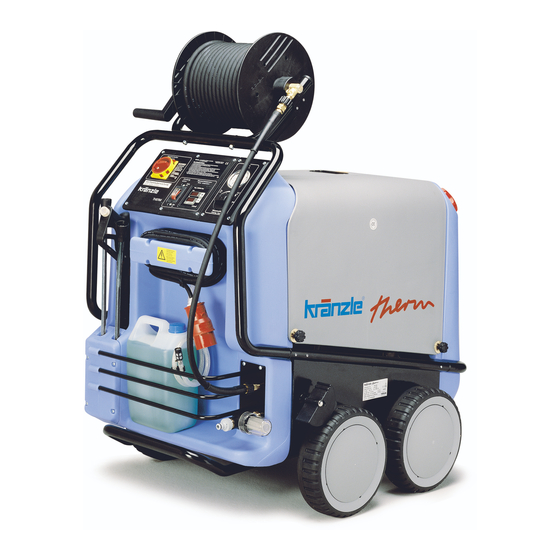
Description Construction and Function Water inlet connection filter Storage bin for spray gun and pipe Power cable Brake 10 Storage bin for accessories Winder for cable Suction hose for detergent 11 Fuel tank 12 Filler aperture for fuel High pressure hose Spray gun 13 High pressure outlet Spray pipe attachment... - Page 4 Description Water and Detergent/Caring Agent System The water flows into a tank. A float valve regulates the water intake. The water is then directed to the safety spray pipe under pressure from the high pressure pump. The high pressure spray is formed through this nozzle on the spray pipe. The high pressure pump can draw a detergent/caring agent at the same time and mix this with the spray.
-
Page 5: Flame Monitor
Description Flame monitor The system is fitted with a flame monitor. The flame monitor prevents fuel being injected if combustion is not taking place. There is a temperature sensor in the exhaust chimney of the combustion chamber, and it is connected to the central electronic control circuit. The burner is switched off if the temperature in the chimney has not reached 100°C within 37 seconds of the burner being started, or if the exhaust gas temperature drops below 100°C for longer than 2 seconds while the engine is in operation. - Page 6 Description Heat exchanger Heat exchanger The heat exchanger is heated by a high pressure fan heater. A ventilator (1) draws in The heat exchanger is heated by a high pressure fan heater. A ventilator (1) draws in the cold, fresh air from the bottom end of the machine and forces it upwards the cold, fresh air from the bottom end of the machine and forces it upwards between the outer mantle (2) and the inner mantle (3).
- Page 7 Description Spray pipe with spray gun The spray gun only allows the machine to be operated when the safety trigger (no. 1) is pulled. The spray gun can be used when the safety trigger is pulled. The liquid is then pumped up to the nozzle.
- Page 8 Description Description Thermostat Thermostat Thermostat The thermostat controls the temperature of the The thermostat controls the temperature of the The thermostat controls the temperature of the spray water. The target temperature is set using spray water. The target temperature is set using spray water.
-
Page 9: Safety Information
Safety Information Safety Information Important!!! The machine must be disconnected from the power supply when servicing work is being carried out. The master switch should be in position "0" and the plug out of the socket. The machine may only be used by persons who have received the necessary training. * Never operate the machine without supervision. -
Page 10: Electrical Connection
Description Electrical connection The voltage given on the specification plate must match the mains voltage. The machine is supplied with a power cable and plug. The plug must be connected to a properly installed electrical socket with earthing and have a 30 mA FI fault current safety switch. The socket must have a neutral 16A fuse on the mains side. -
Page 11: Water Connection
Commissioning If spare parts are required, only properly marked components approved by the maker should be used. High pressure hoses and spray equipment must be connected so that they are pressure-tight. The high pressure hoses should not be driven over, pulled excessively or twisted. Do not pull the hose over sharp edges, since this will invalidate the warranty. -
Page 12: Switching On The Machine
Commissioning Electrical connection Check that the master switch is off (position "0"). Connect the power cable to a properly installed electrical socket with earthing and a 30 mA FI fault current safety switch. The socket must have neutral 16A fusing on the mains side. Switching on the machine - Switch off the ignition. -
Page 13: Adjusting The Pressure
Decommissioning In the interests of the environment and to keep expenditure down, we recommend sparing use of detergent. Please observe the recommendations of the detergent manufacturer. After using detergents, rinse the machine for approx 2 minutes by pressing the trigger of the spray gun. Adjusting the pressure - There are two ways to adjust the working pressure: 1. -
Page 14: Care And Maintenance
Care and Maintenance Care and Maintenance Care and maintenance is required to keep the machine in good working order, and to allow you to enjoy the machine for as long as possible.. IMPORTANT!!! Always remove the plug before working on the machine! What to do! - weekly, or after approx 40 hours of operation * Check the oil lebel on the housing of the high pressure pump... -
Page 15: Changing The Oil
Care and Maintenance Changing the oil The oil of your high pressure pump should be changed after approx 40 hours of operation or if it has a grey or whitish appearance.. To do this, take the oil drainage hose (1) from the inside of the machine and open the oil filler cap (2) on the top side of the oil reservoir. - Page 16 Care and Maintenance Decalcifying the heating element Calcified machines use an unnecessary amount of energy because the water can only be heated slowly and the excess pressure valve feeds a part of the water back into the pump. Calcified machines can be recognised by increased pipeline resistance. Check pipeline resistance by disconnecting the high pressure lance from the gun and switching the machine on.
- Page 17 Inspections Rules, directives, inspections * Inspections performed by Kränzle - measurement of earth line resistance - measurement of voltage and current - inspection of tension consistency with +/- 1530 V - pressure check of heating element at 300 bar - visual and functional check as per the inspection sheet provided - exhaust fukme analysis(see test strips provided) * Guidelines for liquid sprayers The machine conforms with the "Guidelines for liquid sprayers").
-
Page 18: Troubleshooting
Troubleshooting Troubleshooting IMPORTANT!!! Always remove the plug before working on the machine! Multi-function thermostat The thermostat has several functions. Display Possible cause Action "Err OFF" Temperature of over The burner does not switch off properly. Check thermostat, 170° at the sensor thermocouple and klixon and renew if necessary "Err 2"... - Page 19 Troubleshooting Malfunctions without display Malfunction Possible cause Action Machine fails to start No electrical voltage at Check power supply and cables machine Master switch defective Check and replace if necessary Motor protection switch Eliminate cause of overload actuated Press switch (S3 or S5) Check and replace if necessary defective Motor protection (K3) switch...
- Page 20 Troubleshooting Malfunction Possible cause Action High pressure pump Ignition cable defective Check and replace if necessary operates but burner fails to ignite Ignition transformer defective Check and replace if necessary Burner motor (M2) defective Check and replace if necessary Coupling between burner motor Check and replace if necessary and fuel pump defective Fuel pump defective...
-
Page 21: Circuit Diagramme
Circuit diagramme... - Page 22 Terminal box terminal plan...
- Page 23 Cockpit terminal plan 223232323...
- Page 24 Circuit diagramme...
- Page 25 Terminal box terminal plan 52524...
- Page 26 Cockpit terminal plan 3x 220V / 60Hz...
-
Page 27: Pipeline Plan
Pipeline plan High pressure connection Detergent Control and safety block RSB 250 1 Float valve, water inlet 8 Press switch, hose 2 Water tank 9 Safety valve 3 Control valve, detergent 10 Excess pressure line, safety valve 4 High pressure pump 1 1 Flow controller 5 Press switch pump (ND) 12 Fuel pump with magnetic valve... -
Page 28: Complete Assembly
Complete assembly... - Page 29 Hochdruckschlauch NW 8 20 m 41.083 O-Ring 9,3 x 2,4 Viton 13.273 1 Pistole mit Verlängerung - Starlett II 41 053 1 Lanze mit Flachstrahldüse 25045 (für therm 895) 12.392 40.1 Lanze mit Flachstrahldüse 2507 (für therm 1165) 12.392 1 29999999999999999999999999999999999999999999999999999999999999999999999999999999999999999999999...
- Page 30 Switchbox electronics...
- Page 31 Kränzle therm 895 / 1165 Pos. Description Order No. Frontplatte Elektrik 895 44.042 Frontplatte Elektrik 1165 44.042 2 Frontplatte Manometer 44.043 Gummidichtung Elektrik 44.044 Kabeldurchführungsplatte 44.045 Hauptschalter KG32B T203/01E 44.046 Dichtung für Thermostat 44.101 1 Klemme Wago 2,5 mm² 44.047 Manometer 15.039 1...
- Page 32 Water supply Water supply Pos. Description Order No. Wassertank 44.009 Schwimmerventil 44.025 Distanzring 44.026 Anschlußstück R 3/8" IG 41.423 Einströmschlauch 44.027 O-Ring 13 x 2,6 13.272 Schlauchtülle 44.126 Überwurfmutter 41.047 Schlauchschelle 12 - 22 44.054 2 Wassereingangsschlauch 44.028 Schlauchtülle R3/8" x 13 44.029 Ermetorohr 12 mm 44.030...
-
Page 33: Fuel Supply
Fuel supply Pos. Description Order No. Deckel Brennstoffversorgung 44.011 Flansch mit Brennstoffleitungen 44.010 Gummidichtung 44.012 Schwimmerschalter 44.014 Rücklaufschlauch 44.015 Schlauchschelle 7 - 11 44.054 Einschraubwinkelverschraubung 1/4" x 6 44.062 Kunststoffschraube 4,8 x 25 41.414 Kugelhahn 44.203 Anschlußteil Brennstofffilter 44.214 Gummidichtung 3/4" 41.047 1 Filtergrundkörper 13.301... -
Page 34: Heat Exchanger
Heat exchanger... - Page 35 Kränzle therm 895 / 1165 Pos. Description Order No. Außenmantel 44.063 Heizschlange mit Innenmantel 44.064 Hydrospeicher 44.140 Innendeckel 44.065 Außendeckel 44.066 Anschlußmuffe für Hydrospeicher 44.140 1 Gebläsestutzen 44.068 Gebläsegehäuse 44.069 Gebläsedeckel 44.070 1 Lüfterrad 44.071 Brennermotor 220 V / 50 Hz 44.072...
- Page 36 Control and safety block Pos. Description Order No. Ventilgehäuse Sicherheitsblock 40.590 Verschlußschraube R 1/8" IG 40.591 Dichtstopfen M 8 x 1 13.158 Dichtstopfen M 10 x 1 43.043 O-Ring 15 x 2 13.150 Kolbenführung spezial 42.105 Stömungskörper 40.592 O-Ring 11 x 1,44 12.256 Edelstahlsitz 8,2 mm 13.146...
- Page 37 Terminal box and transformer Pos. Description Order No. Konsole mit integr. Klemmkasten 44.067 1 Transformator 230 V / 50 Hz 44.074 Kunststoffschraube 4,0 x 25 43.425 Deckel für Klemmkasten 44.075 2 Hutschiene für Verteilerkasten 44.125 Durchgangsklemme grau 44.047 Durchgangsklemme grün/gelb 44.048 Querbrücker 24 A 44.047 1...
- Page 38 Connections...
- Page 39 Kränzle therm 895 / 1165 Pos. Description Order No. Aggregathalterung 44.013 Halteblech Sicherheitsblock 44.095 Innensechskantschraube M 12 x 45 40.504 Elastic-Stop-Mutter M8 41.410 Unterlegscheibe 8,4 DIN 9021 41.409 Innensechskantschraube M 8 x 30 41.036 1 Schlauchschelle 7 - 10 44.054 Schlauchtülle 3/8"...
-
Page 40: Transmission Unit
Transmission unit... - Page 41 Kränzle therm 895 / 1165 Pos. Description Order No. Ölgehäuse 40.501 Innensechskantschraube M 8 x 25 40.053 Sicherungsscheibe 40.054 Flachdichtung 40.511 Öldichtung 20 x 38 x 7 40.044 1 Wellenscheibe 40.043 Axial-Rollenkäfig 40.040 AS-Scheibe 40.041 Taumelscheibe 9,5° bei 895 400V / 50Hz 40.042 1-9,5...
-
Page 42: Valve Housing
Valve housing Pos. Description Order No. Ventilgehäuse 40.502 1 O-Ring 18 x 2 40.016 Einlaß- / Auslaß- Ventil 42.024 O-Ring 21 x 2 42.025 Ventilstopfen 42.026 Sicherungsring 40.032 Innensechskantschraube M 12 x 45 40.504 Gewebemanschette 40.023 Backring 20 mm 40.025 O-Ring 31,42 x 2,62 40.508 1 Leckagering 20 x 36 x 13,3... - Page 43 Kränzle therm 895 / 1165 Motor Pos. Description Order No. Stator 112 5,5 kW 400V / 50Hz 40.540 Stator 112 3x 220V / 60 Hz 40.541 A-Lager Flansch 40.530 Rotor 112 40.531 Lüfterrad BG112 40.532 Lüfterhaube BG 112 40.533 Klemmkasten 40.534...
- Page 44 Kränzle therm 895 / 1165 Pressure switch Pos. Description Order No. Gehäuse (schwarz) 15.007 Gehäuse (rot) 15.007 1 Deckel (schwarz) 15.008 Deckel (rot) 15.008 1 Gehäuse Steuerkolben 15.009 Steuerkolben 15.010 Ausgangsteil R 1/4" AG 15.011 Parbaks 7 mm 15.013 O-Ring 5 x 1,5 15.014...
- Page 45 Düsenschutz 26.002 Rohr 500 mm; bds. R1/4" 12.385 1 ST 30 Nippel M 22 x 1,5 / R1/4" m. ISK 13.370 Flachstrahldüse 25045 (bei therm 895) D25045 54.1 Flachstrahldüse 2507 (bei therm 1165) D2507 Starlet-Pistole kpl. mit Verlängerung 12.320 2 Rep.-Satz "Starlet II"...
-
Page 46: Hose Drum
Hose drum (Special accessory) Supplementary Parts: 44.152... - Page 47 Kränzle therm 895 / 1165...
- Page 48 NOTES...
- Page 49 I. Kränzle GmbH Elpke 97 . 33605 Bielefeld EC declaration of conformity as defined by machinery directive 89/392/EEC Annex II A Herewith we Kränzle therm 895, 1165 declare that 91/368 EWG Anh. I Nr. 1 complies with the following 73/23 EWG...
-
Page 50: Inspection Sheet
Inspection Sheet Custumer:____________________ Mixing facility: MEKU Number of slots: Diameter of hole: 22 mm All lines connected Hose clamps tight Screws all installed and tightened Ignition cable plugged in Visual check carried out Brake function checked Sealing check: Float box filled and checked Water inlet checked for tightness Float valve function checked Machine checked for tightness under pressure... - Page 51 Kränzle therm 895 / 1165 Thermostat function checked Fuel warning switch checked Burner function checked: 70 72 74 76 78 80 82 84 86 88 90 Water temperature reached: °C Fuel pressure: 8 8,5 9 9,5 10 10,5 11,5 Measured soot count:...
-
Page 52: Inspection Log
Inspection log 1st Inspection Performed by Kränzle as per the inspection record supplied with the machine 2nd Inspection ___________ Date Performed by________________________ Stamp/signature 3rd Inspection ___________ Date Performed by________________________ Stamp/signature 4th Inspection ___________ Date Performed by________________________ Stamp/signature 5th Inspection 6th Inspection ___________ Date Performed by________________________...
Need help?
Do you have a question about the therm 895 and is the answer not in the manual?
Questions and answers