
Related Manuals for Kranzle 602 E-M 18


Summary of Contents for Kranzle 602 E-M 18
- Page 1 O p e r a t i n g m a n u a l Hot Water High-Pressure Cleaners - electrically heated 602 E-M 18 602 E-M 24 602 E-M 36 872 E-M 48 Read and conform safety instructions before use!
-
Page 2: Table Of Contents
Contents Contens ........................ 2 Overview ’This is what you have purchased’ ..............4 Description of appliance ....................5 Tecnical data ........................ 6 General rules ........................ 8 Safety precautions – accident prevention ..............9 Water connection – electrical connection ..............11 Putting into operation ....................12 Usage as a cold water high pressure cleaner ........14 Usage as a hot water high pressure cleaner ......... 15 Kränzle- technology ....................16 Water and cleaning system ..............16 Lance and spray gun ................16 Total stop system . - Page 3 Page Spare parts lists ......................30 Water supply ..................30 Heating element 18 / 24 kW ..............32 Heating element 36 / 48 kW ..............33 Electric module 18 / 24 kW ..............34 Electric module 36 / 48 kW ..............36 Engine mounting ..................38 Unloader valve and pressure switch ............40 Pump .....................42 Pump motor ...................44 Valve housing ..................45 Electronics switchbox ................46 Safety valve ...................48 Gun 'Starlet' ...................50 Pipeline plan ......................51 Wiring diagram 18 / 24 kW ..................52 Wiring diagram 36 / 48 kW ..................53 Inspection reports - attestation forms................54 EG – Declaration of Conformity ...................58 Guarantee ......................59...
-
Page 4: Overview 'This Is What You Have Purchased
This is what you have purchased Kränzle hot water high-pressure cleaners therm E-M, electrically heated, with hose drum and 20 m steel-weave high-pressure hose Kränzle hot water high-pressure cleaners therm E-M, electrically heated, without hose drum but with 10 m steel- weave high-pressure hose Safety spray gun with insulated handle and screw connection Spray lance Operating manual... -
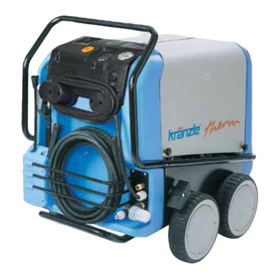
Page 5: Description Of Appliance
Gerätebeschreibung Kränzle therm E-M Hose drum with 20 m steel fabric high-pressure hose Operating panel Filling hole for detergents Winding device for mains lead electric connection cable with plug Detergent tank Detergent switch High-pressure outlet Drain screw for detergent Water inlet part with filter Power switch (appliance ON-OFF) Heating switch (burner ON/OFF) Brief operating instructions Digital thermostat for adjusting water temperature Pressure gauge – high pressure... -
Page 6: Tecnical Data
Tecnical data therm 602 E-M 18 Operating pressure, continuously adjustable, nozzle size 25045 30 - 100 bar Operating pressure, continuously adjustable, nozzle size 2503 30 - 160 bar Admissible overpressure, nozzle size 25045 120 bar Admissible overpressure, nozzle size 2503 170 bar Water output 180 - 600 l/h Maximum hot water discharge 60 °C at 32 bar... - Page 7 therm 602 E-M 24 therm 602 E-M 36 therm 872 E-M 48 30 - 100 bar 30 - 100 bar 30 - 170 bar 30 - 160 bar 30 - 160 bar 120 bar 120 bar 190 bar 170 bar 170 bar 180 - 600 l/h 180 - 600 l/h 180 - 870 l/h 72 °C bei 32 bar 80 °C at 32 bar 80 °C at 32 bar by 34 °C with 10 l/min by 50 °C with 10 l/min by 46 °C with 14 l/min 60 °C 60 °C 60 °C 10 m 10 m 10 m 400 V, 41,2 A, 50 Hz 400 V, 58,6 A, 50 Hz 400 V, 80 A, 50 Hz 26,6 kW 38,6 kW 53,5 kW...
-
Page 8: General Rules
General rules Range of application This machine may only be used for cleaning facades, vehicles, containers, pavement slabs, stables, machines and similar objects. Inspections The machine must be inspected according to the “Guidelines for Liquid Spray Devices” at least once every 12 months by a qualified person, to ensure that continued safe operation is guaranteed. The results of the inspection are to be recorded in writing. This may be done in any form. For inspection reports see pages 54/57. High-pressure cleaners used for commercial purposes have to be checked by a qualified person at least every 12 months! Accident prevention The machine is designed for accidents to be impossible (if used according to these instructions). Please read safety notes included in these instructions carefully before using the machine and act correspondingly. Operating staff has to be instructed according to this manual. The “Guidelines for Liquid Spray Devices” must be complied with. Setting up - Location Neither set up and operate the machine in rooms where there is a risk of fire or explosion nor put it into puddles. -
Page 9: Safety Precautions - Accident Prevention
Safety notes Never operate the machine without supervision. The machine may only be operated by persons who have been instructed accordingly. Some parts inside the machine, all water conducting components and all metal parts of gun and lance are hot during hot water operation. Keep all hoods and protective covers closed during operation and never touch any metal parts of gun or lance. - Page 10 Safety notes - This is prohibited! Never direct the water jet at people or animals! Only use power cables which are in perfect working order! Do not damage the power cable or repair it incorrectly! Never pull the high pressure hose if it has formed kinks or “nooses”! Never pull the hose over sharp edges! Never allow children to use the high...
-
Page 11: Water Connection - Electrical Connection
Connection to water supply Please pay attention to the regulations of your waterworks company! In accordance with DIN EN 61770, the machine may not be directly connected to the public drinking water supply lines. A brief connection however is permissible according to DVGW (German Association for Gas and Water Affairs) if a tube ventilator with check valve (Kränzle Order-No. 41.016 4) is built into the water supply. Also indirect connection to the public drinking water supply lines is permissible by way of free emission in accordance with EN 61 770; e.g. by using a reservoir with a float valve. Direct connection to a non-drinking water supply line is permissible. Electrical connection The voltage given on the specification plate must match the mains voltage. The machine is supplied with power cable without plug. The plug has to be equipped with a safety earth terminal and a 30 mA residual-current circuit breaker. The mains connection has to be fused with a time-delay fuse according to the specifications on page 6/7. -
Page 12: Putting Into Operation
Putting into operation Steering the machine: To change direction tilt machine by pressing a foot against the footrest and pull the handle at the same time. Then turn machine into desired direction. Always secure machine by activating the parking brake before starting work! . Check water inlet filter for cleanliness prior to putting the machine into operation! Unscrew glass body of the inlet filter and check if metal sieve is soiled. Always check oil level prior to operation! Open the right half of the protecting hood. Do not start the machine if the oil level is not between the two markings on the oil-level glass. Refill with oil if necessary. See page 23 Connect machine to water mains (2 - 8 bar pre-pressure). - Page 13 Connect to power circuit. Make sure that the main switch is on the "OFF" position. The socket must be protected by means of a time-delay fuse on the mains side (for details as to ampere values see technical data on pages 6/7). For appliances without hose drum: Screw high-pressure hose to the high-pressure outlet pressure-tightly. Release fixation of hose drum. Unwind high-pressure hose from the hose drum without any kinks or nooses. Attach high-pressure hose to the gun and screw together pressure-tightly. Take care that all screw connections are pressure-tight. A leakage of gun, high-pressure hose or hose drum has to be repaired at once. Leakages lead to an increased wear and to a possible malfunction of the delayed motor cut-out.
-
Page 14: Usage As A Cold Water High Pressure Cleaner
Usage as a cold water high-pressure cleaner Switch on main switch located below the right part of the machine hood. (switch to "ON") Ignition switch to -OFF- position Detergent valve must be closed! (switch in left end position) Switch on main switch with disengaged spray gun. Vent high-pressure cleaner: Pull and release trigger of spray gun repeatedly. The operating pressure is regulated my means of the pressure regulating valve at the pump head: turn the knob to the left to decrease the operating pressure; turn it to the right to increase the operating pressure. Start cleaning task. -
Page 15: Usage As A Hot Water High Pressure Cleaner
Usage as a cold water high-pressure cleaner Switch on main switch located below the right part of the machine hood. (switch to "ON") a) Temperature mode: Set required temperature at the thermostat. (Min. temperature 40 °C) b) Percentage mode: Set percentage value for heating output. (see pages 18/19) Detergent valve must be closed! (switch in left end position) Switch on main switch with disengaged spray gun. Vent high-pressure cleaner: Pull and release trigger of spray gun various times Start ignition. The water is heated up and constantly kept at the set temperature. Start cleaning task During high-pressure operation (above 30 bars) the temperature may not exceed 90 °C! During steam operation (90 - 150 °C) the pressure may not exceed 30 bar) To reach the steam level (above 90 °C water temperature) adjust the... -
Page 16: Kränzle Technology
Kränzle technology Water and cleaning system The water is fed to the high-pressure cleaner under pressure (2-8 bar pre-pressure). A float valve regulates the water flow in the storage tank. Then the water is sucked directly from the storage tank by the high-pressure pump and forced with the adusted pressure through the heat exchanger to the safety spray lance. The high pressure jet is formed by the nozzle at the end of the safety lance. Environmental, refuse disposal and water protection regulations must be observed! Lance with trigger gun The machine can only be operated when the safety trigger is squeezed. When the lever is squeezed, the spray gun opens. The liquid is then pumped to the nozzle. The spray pressure increases and quickly reaches the selected operating pressure. When the trig- ger is released, the trigger gun closes and any further spraying of liquid from the lance is stopped. The motor stops. When actuating the gun once more the pressure control valve - safety valve closes and the motor is started again. The pump resumes feeding water to the spraying lance with the selected operating pressure. When the gun is closed, the water hammer opens the pressure control valve - safety valve and the motor is switched off by the pressure switch. The trigger gun is a safety device. Repairs should only be performed by qualified persons. -
Page 17: High Pressure Hose And Spray Device
High pressure hose and spraying device The high pressure hose and spraying device supplied with the machine are made of high grade material, they are also optimized for the machine and marked as required by the appropriate regulations. If replacement parts are required, only such parts that are authorized by the manufacturer and which bear the markings required by the appropriate regulations may be used. The high pressure hose and spray device must be connected in a pressure-tight manner. -
Page 18: Thermostat
Kränzle technology Thermostat The thermostat controls the spray water temperature. After you switch on the device, "888" appears in both displays for approx. 1 second as a test of the functioning of the displays. 12 3 The thermostat has two operating modes: 1. Temperature mode This mode is always activated when the unit is switched on or can be selected using the "°C°" button (Pos. 3). The red LED above the "°C" button and next to the set temperature display lights up. The desired "Set" temperature is set using the two buttons (+/-, Pos. 5+6) and can be read in the upper display (Pos. 1). If you press the button for a longer time, the set temperature is quickly adjusted in 5°C increments. The last set value set is also stored after the unit is switched off and is available again immediately after switching back on. The current spray temperature can be read from the bottom display (Pos. 2). 2. Percentage mode This mode is activated by pressing the "%" button (Pos. 4). The yellow LED above the "%" button and next to the set temperature display flashes. In the temperature control system in conventional high pressure cleaners, and in temperature mode for this unit, the water temperature is measured at the outlet of the heater, and the heater is switched on an off according to the temperature desired by the user. Due to the large amount of water in the heating coil, it takes a long time until the temperature sensor registers that the burner has switched on and the desired temperature has been reached. This means that the temperature increases far above the desired value or falls far below the desired value. - Page 19 Thermostat - Percentage mode The innovative new percentage mode now lets the user specify the switching duration of the heater in percent using the "+" and "-" buttons (Pos. 5+6) (100% being the max. temperature) rather than setting the desired temperature. Now the result of the setting must be checked by using the "Actual" temperature display. If the desired temperature has not yet been reached, the percentage must be increased. By setting percentages of the heating duration, the temperature of the high pressure jet is kept constant in a very narrow range. The last value set is also saved after the unit is switched off in percent mode. Operating hour meter The cleaner is equipped with an operating hour meter. If during normal operation the momentary operating mode button ( "°C" or "%" ) is actuated for more then 2 seconds, the operating time of the pump is displayed for 5 seconds and afterwards the combustion time for 5 seconds as well. Thereafter the display shows the original values again. As long as the operating hours are displayed no further inputs on the monitor are possible. The operating time is displayed in hours [ h ] either in the “TARGET” or in the „ACTUAL“ window. The 1000 and 100 hours are displayed in the „TARGET“ window and the 10, 1 and 1/10 hours in the “ACTUAL” window: Pump operating time: Target-Display: P 9 9 Actual-Display: 9 9. 9 for 9 999.9h Combustion time: Target-Display: F 9 9 Actual-Display: 9 9. 9 for 9 999.9h e.g.: F00 27.3 = Cumbustion time 27 hours and 18 minutes Displayed malfunctions Anzeige im Feld Ursache Abhilfe SOLL Gerät ohne Heizung „Heizung AUS“...
-
Page 20: Electric Heating
Kränzle technology Electric heating 18, 24, 36, 48 kW The flow heaters are connected in series in modular design according to machine type and kW output. For water temperature at max. water output we refer to the table on pages 6/7, second column „Heating of sucked in water“. To be able to reach the maximum hot water output temperature it might be necessary to reduce the operating pressure, thus reducing the water output in l/min at the same time (see page 17). For the temperature values we refer once more to the table on page 6/7, see „max. hot water output“ Flow heater... -
Page 21: Suction Of Detergents
Suction of detergents Detergent supply from the suction side: Detergent injection on the pressur side, as you probably know it from other HP cleaners, consume approx. 30 % of the cleaning energy, no matter if they are used or not. Due to the water tank fitted to the Kränzle therm cleaners it is now possible to directly suck the detergent into the pump thus reducing output loss and increasing the efficency considerably. The detergents are applied without having to reduce the working pressure. Place detergent filter into detergent container. Dosing of detergent is done by turning the detergent valve. By closing the detergent valve the supply of detergent is stopped. After having used detergents rinse the appliance with open spray gun and clean water for at least 2 minutes. Only open the dosing valve, if the detergent sieve is placed in a liquid. -
Page 22: Decommissioning - Frost Protection
Decommissioning - frost protection 01. Switch off the machine - main switch to „0“- position 02. Cut off the water supply 03. Open the spray gun briefly until the pressure is released 04. Apply the safety catch on the spray gun 05. -
Page 23: Care And Maintenance (Weekly/Yearly)
Care and Maintenance The machine must be disconnected from the power supply when servicing work is being carried out. The main switch should be in position "0" and the plug out of the socket. Weekly, or after approx. 40 hours of operation: - Check the oil level of the high pressure pump. If the oil level is too low, add oil until the oil level is between the two markings on the oil measuring rod. -
Page 24: Decalcifying The Continuous-Flow Heater
Decalcifying the continuous-flow heater: Calcified machines use an unnecessary amount of energy because the water can only be heated slowly and the excess pressure valve feeds a part of the water back into the pump circuit. Calcified machines can be recognised by increased pipeline resistance. Check pipeline resistance by disconnecting the high pressure lance from the gun and switching the machine on. A full jet of water emerges from the gun. The machine must be decalcified if the pressure shown on the manometer is greater than 25 bar. Proceed as follows to decalcify the machine: Unscrew the high pressure hose from the machine and decalcify it separately. Put the detergent suction hose into a container of decalcifying solution. Set the detergent valve to the maximum concentration. Switch on the machine. Hold the gun in a separate container and press the trigger. Wait for about a minute until the decalcifier comes out of the gun (recognisable by its whitish colour) Switch off the machine and allow the solution to act for about 15-20 minutes. Switch the machine back on and rinse with clear water for about 2 minutes. Now check whether pipeline resistance is back to an acceptable level. Repeat the decalcifying process if the pressure without the high pressure lance is still above 25 bars. -
Page 25: Particular Rules, Directives And Inspections
Particular rules, directives and inspections Inspections performed by Kränzle - measurement of earth line resistance - measurement of voltage and current - inspection of tension consistency with +/- 1530 V - pressure check of heating coil at 300 bar - visual and functional check as per the inspection sheet provided Guidelines for liquid sprayers The machine conforms with the "Guidelines for liquid sprayers". These guidelines are issued by the organisation of trade associations and may be obtained from Carl Heymann-Verlag KG, Luxemburger Str. 49, 50939 Köln. These guidelines specify that this machine is to be inspected by qualified personnel whenever necessary, but no less than once every 12 months. These inspections must be recorded in the inspection log at the end of this manual. Pressure container and steam boiler directives Kränzle high pressure cleaning equipment conforms to the pressure container and steam boiler directive. No construction approval, notification of licence and takeover inspection are required. The water capacity is less than 5 l. Duties of owner The owner is to ensure that all safety-relevant components are in a serviceable condition before the sprayer is used. (e.g., safety valves, hose and electric cables, spray equipment etc). -
Page 26: Troubleshooting
Troubleshooting Malfunction Cause of malfunction / remedy Water supply Water tank runs over. Float valve is dirty or defective. Water tank does not fill completely. Float valve is defective. Water filter is dirty. Insufficient water inlet quantity. Pump does not suck. Valves stick or are dirty. Suction hose leaks. Chemistry valve is open or leaks. Check hose clips (connections). High-pressure nozzle is clogged. Test: check water and chemical Connect water inlet directly to the pump (2-8 bar system for tightness. pre-pressure). Disconnect suction lines below the pump High-pressure pump Pump makes loud noises. Pump sucks air. Check suction connections. Operating pressure is not reached. Check high-pressure nozzle. Check valves. Check O-rings under valves. Check sleeves. Manometer is defective. Unloader: check stainless steel seat and ball. Check seals on the control piston. Water drops from the pump. Replace sleeves in the pump. Replace O-rings. Oil drops from the transmission. Check oil seals (replace). Check plunger and plun- ger guides. Check water supply, since water defici- ency or air suction can cause damage to seals and O-rings (chemistry valve leaks?) Pressure is too low. - Page 27 Malfunction Cause of malfunction / remedy Machine does not start Check electricity supply. Check main switch. Check cable connections. Board defective. Check pressure switch. Switch off by overcurrent release. Electrical heating elements Insufficient water temperature. Check electricity: - ON-OFF - Switch - Contactor - Flow monitoring device Leakage Gun drips. High pressure hose drips. Clean nozzle. Replace seals. Replace O-ring below screwed connection. Manometer indicates pressure, but no Clean nozzle. water comes out of HP-hose.
-
Page 28: Small Repairs Do It Yourself
Small repairs do it yourself No water from the nozzle but the gauge shows full pressure: Most likely the nozzle is blocked. (Inside the pressure gauge there is no water but a filling with glycol to damp the vibration of the pointer.) Proceeding: Switch off the cleaner. Pull plug from the socket. Operate gun seveal times to decrease the pressure. First unscrew gun and lance, then rinse hose from any residues. Check water inlet filter for soiling. If the problem still exists, take wire (paper clip) and push cautiously through nozzle opening. If this procedure is not successful, the nozzle has to be dismantled and cleaned (from the backside) or even replaced, if necessary. Pressure gauge shows little pressure, the water from the nozzle comes squirts, the high-pressure hose vibrates. - Page 29 The pressure gauge shows full pressure although the gun has been closed. The pressure switch valve switches constantly. Possible cause no.1: Leakage Having closed th gun, the HP cleaner must shut down and the pressure gauge must show „0“ bar. If the pressure gauge still shows full pres- sure and the motor constantly switches on and off, the possible reason for this can be a leakage of the pump, the HP hose or the lance. Proceeding: Check the connections from the HP cleaner to the the HP hose, from the hose to the gun and also the connection between lance and gun for tightness. Switch off the cleaner. Shortly press the trigger of the gun to decrease the pressure. Unscrew HP hose, gun and lance and check the O-rings. If the O-rings are damaged they have to be replaced. In case of a leakage there is no guarantee for possible consequential damages.
-
Page 30: Water Supply
Complete assembly... - Page 31 Kränzle therm 602 E-M 18/24/36, therm 872 E-M 48 Description Qty. Ord.-No Cockpit 44.351 Chemietank 44.004 Wasserkasten 44.009 Lanzenköcher 44.008 Haube rechts 44.032 Haube links 44.031 Rad 44.017 Radkappe 44.018 Bremspedal 44.022 Bremshebel 44.023 Bremsklotz 44.024 Tankdeckel mit O-Ring 44.005 Fahrgestell 44.001 Frontbügel 44.002 Schubbügel...
- Page 32 Electronics switchbox...
- Page 33 Kränzle therm 602 E-M 18/24/36, therm 872 E-M 48 Description Qty. Ord.-No Position Bezeichnung Stck. Bestell-Nr. Elektrokasten 44.807 1 Deckel für Elektrokasten therm 47.014 1 Frontplatte Manometer 44.375 1 Kabelaufwicklung 44.822 Schraube 5 x 25 41.414 1 Bock für Schalter 44.810 Schraube 5,0 x 14 43.426 Bock für Thermostat 47.012 Dichtung für Thermostat 47.013 Dichtung für Schalter 44.817 Schalter 44.835 Mutter M4 40.111 Dichtung für Deckel Übertemp.
-
Page 34: Electric Module 18 / 24 Kw
Water supply... - Page 35 Kränzle therm 602 E-M 18/24/36, therm 872 E-M 48 Description Qty. Ord.-No Wassertank 44.009 Schwimmerventil 46.250 5 Mutter R3/4“ 46.258 Anschlussstück R 3/8“ IG 41.423 Einströmschlauch 44.027 O-Ring 13 x 2,6 13.272 Schlauchtülle 44.126 Überwurfmutter 41.047 Schlauchschelle 12 - 22 44.054 2 Wassereingangsschlauch 44.028 Schlauchtülle R3/8“ x 13 44.029 HD-Schlauch Wasserausgang 44.840 Haltescheibe 44.841 Schraube DIN912 M 5 x 12 41.019 4 Wasserausgangsteil 44.855...
- Page 36 Heating element Kränzle therm 602 E-M 18 / 24 Description Qty. Ord.-No 01 Andrückblech 44.7541 02 Moosgummidichtung 44.7551 03 Zentrierblech 3 Heizstäbe 44.756 04 Hochdruckschlauch Eingang/Ausgang 44.702 05 Ermetoverschraubung Winkel gelb verzinkt 44.865 06 Ausgangsteil Pumpe für Kräzle therm 44.215 07 Ermeto T-Stück 44.141 08 Ermetoverschraubung T-Stück gelb verzinkt 44.173 09 Eingangsstück R3/8“ IG für UL 250 13.136 10 Nippel 3/8“ IG auf M22 AG...
- Page 37 Heating element Kränzle therm 602 E-M 36, therm 872 E-M 48 Description Qty. Ord.-No 01 Andrückblech 44.7541 02 Moosgummidichtung 44.7551 03 Zentrierblech 3 Heizstäbe 44.756 04 Hochdruckschlauch Eingang/Ausgang 44.702 05 Ermetoverschraubung Winkel gelb verzinkt 44.865 06 Ausgangsteil Pumpe für Kräzle therm 44.215 07 Ermeto T-Stück 44.141 08 Ermetoverschraubung T-Stück gelb verzinkt 44.173 09 Eingangsstück R3/8“ IG für UL 250 13.136 10 Nippel 3/8“ IG auf M22 AG...
-
Page 38: Engine Mounting
Electric module 18/24 kW... - Page 39 Kränzle therm 602 E-M 18/24 Description Qty. Ord.-No 01 Heizungsgehäuse VA 44.746 02 Sicherungsautomat 16 A 44.617 03 Zeitrelais (einschaltverzögert) 44.634 04 Schütz AEG 63A 44.6211 05 Leitungsschutzschalter AEG B32 18 KW 44.616 05 Leitungsschutzschalter AEG B40 24 KW 44.6161 06 Fernauslöser 176158 44.618 07 Hauptschalter 63 A 44.622 08 Anschlußkabel 4x6 qmm 18 KW 44.610 08 Anschlußkabel 4x10 qmm 24 KW 44.6101 09 Gewindestange Edelstahl 44.6241...
-
Page 40: Electric Module 36/48 Kw
Electric module 36/48 kW... - Page 41 Kränzle therm 602 E-M 36, therm 872 E-M 48 Description Qty. Ord.-No 1 Heizungsgehäuse VA 44.746 2 Sicherungsautomat 16 A 44.617 3 Schütz DIL M32 230V 50Hz 44.6211 4 Fernauslöser 176158 44.618 5 Leitungsschutzschalter AEG B32 bei 36 kW 44.616 6 Hauptschalter Therm elektrisch 18 – 36 kW 44.215 6 Hauptschalter Therm elektrisch 48 kW 44.6221 7 Anschlußkabel bei 36 kW 44.611 7 Anschlußkabel bei 48 kW 44.612 8 Gewindestange Edelstahl 44.6241 9...
-
Page 42: Unloader Valve And Pressure Switch
Unloader valve and pressure switch... - Page 43 Kränzle therm 602 E-M 18/24/36, therm 872 E-M 48 Description Qty. Ord.-No O-Ring 16 x 2 13.150 5.1 O-Ring 13,94 x 2,62 42.167 O-Ring 11 x 1,44 12.256 Edelstahlsitz 14.118 Sicherungsring 13.147 Edelstahlkugel 8,5 mm 13.148 Edelstahlfeder 14.119 Verschlussschraube 14.113 Steuerkolben 14.134 Parbaks 16 mm 13.159 Parbaks 8 mm 14.123 Spannstift 14.148 Kolbenführung spezial 42.105 Mutter M 8 x 1 14.144...
-
Page 44: Pump Motor
Valve housing... -
Page 45: Valve Housing
Kränzle therm 602 E-M 18/24/36, therm 872 E-M 48 Description Qty. Ord.-No Ventilgehäuse AM-Pumpe 40.451 O-Ring 15 x 2 41.716 Ventile (grün) für APG-Pumpe 41.715 1 O-Ring 16 x 2 13.150 Ventilstopfen 41.714 Innensechskantschraube M10 x 35 42.509 1 Ansaugschlauch mit Nippel R1/4“ 44.096 4 Dichtring 40.019 Verschlussschraube 3/8“ mit R1/4“ IG Manschette 18 x 26 x 4/2 41.013 Backring 18 mm 41.014 O-Ring 40.026 Leckagering 18 mm 41.066 Gewebemanschette 18 x 26 x 5,5/3 41.013 1 Zwischenring 18 mm 41.015 2... -
Page 46: Electronics Switchbox
Kränzle therm 602 E-M 18/24/36, therm 872 E-M 48 Pump Description Qty. Ord.-No Ölgehäuse mit Öldichtungen 40.452 Innensechskantschraube M 8 x 25 40.053 Sicherungsscheibe 40.054 Flachdichtung 40.511 Öldichtung 18 x 28 x 7 41.031 Wellenscheibe 40.043 Axial-Rollenkäfig 40.040 AS-Scheibe 40.041 11.1 Swash plate 7,66° (therm 602) 40.460-7,66 11.2 Swash plate 10,8° (therm 872) 40.460-10,8 Plungerfeder 40.453 Federdruckscheibe 40.454 Plunger 18mm (AM-Pumpe) 40.455... - Page 47 Kränzle therm 602 E-M 18/24/36, therm 872 E-M 48 Pump motor Description Qty. Ord.-No Stator BG100 4,8 kW 400V / 50Hz 40.710 Lager Flansch 40.700 Rotor BG100 400V / 50Hz 40.703 Lüfterrad BG100 40.702 Lüfterhaube BG 100 40.701 10 Schrägkugellager 7306 40.704 11 Öldichtung 35 x 47 x 7 40.080 12 Passfeder 8 x 7 x 28 40.459 13 Kugellager 6206 - 2Z 40.538 14 Innensechskantschraube M 6 x 30 43.037 15 Toleranzhülse...
-
Page 48: Safety Valve
Flow-Safety-Block (Adjustment must be approx. 15% above the operating pressure) - Page 49 Kränzle therm 602 E-M 18/24/36, therm 872 E-M 48 Description Qty. Ord.-No Ventilkörper FSB250-1 14.215 Dichtstopfen M 8 x 1 13.158 Ermetoverschraubung R 3/8“ x 12 mm Rohrstutzen 44.365 Stopfen R1/4“ 13.387 Ermetowinkel R 1/4“ x 6L 44.062 Spannstift 14.148 Steuerkolben 14.110 O-Ring 16 x 2,0 13.150 Kolbenführung 14.130 Parbaks 16 mm 13.159 Parbaks 8 mm 14.123 Hydrospeicher 44.140 L-Verschraubung 44.869 Anschlussmuffe für Hydrospeicher 44.140 1 Ventilfeder 14.125...
-
Page 50: Gun 'Starlet
Spare parts list Kränzle E-M Gun 'Starlet' Description Qty. Ord.-No Seitenschale Schlauchführung 40.302 Ventilkörper mit Handgriff 12.294 Schutzhülse 12.295 Abdeckschutz 12.296 Betätigungshebel grau 12.298 3 Sicherungshebel 12.149 Abschlussschraube M 16 x1 12.247 Stopfen 12.287 Gewindeführungshülse Ø3 R 1/4“ AG 12.250 1 Aufsteuerbolzen Ø3 12.284 1 Stift 12.148 Lagernadel 12.253 Edelstahlfeder 12.246 Edelstahlkugel 8,5 12.245 Edelstahlsitz Ø7 14.118 O-Ring 11 x 1,44 12.256 O-Ring 3,3 x 2,4... -
Page 51: Pipeline Plan
Pipeline plan Safety valve, number 5 must be set approx. 15 % higher than the unloader valve on the HP pump 1 Float valve, water inlet 2 Water tank 3 Control valve detergent 4 High pressure pump with integrated unloader valve 5 Safety valve for heating coil Safety valve excess pressure line 7 Flow controller 8 Heating elements... -
Page 52: Wiring Diagram 18 / 24 Kw
Spare parts list Kränzle therm E-M Wiring diagram 18 / 24 kW... -
Page 53: Wiring Diagram 36 / 48 Kw
Spare parts list Kränzle therm E-M Wiring diagram 36 / 48 kW... -
Page 54: Inspection Reports - Attestation Forms
Inspection report for HP cleaners Inspection report on annually carried out Labour Safety Inspection (UVV) according to the Guidelines for Liquid Spray Equipment. (This inspection sheet serves as proof for the completion of the retest and must be kept carefully!) Kränzle-Test Stamp Mark: Order Number UVV200106 Owner: Type therm: Address: Serial no.: Rep.-order-no.: Scope of inspection: ok yes repaired Type plate (on hand) Operating manual (on hand) Protective covering, -device Pressure line (tightness) Pressure gauge (function) Float valve (tightness) Spraying device (marking) HP-hose/ connector (damage, marking) Safety valve opens at 10% / 20% excess Pressure reservoir Heating oil line (tightness) Solenoid valve (function) Thermostat (function) Flow controller (function) Power cable (damage) Power plug (damage) Protective conductor (connected) Emergency Off Switch (function) On/Off-switch Water quantity safety device (function) Used chemicals Allowed chemicals Inspection data determ. - Page 55 Inspection report for HP cleaners Inspection report on annually carried out Labour Safety Inspection (UVV) according to the Guidelines for Liquid Spray Equipment. (This inspection sheet serves as proof for the completion of the retest and must be kept carefully!) Kränzle-Test Stamp Mark: Order Number UVV200106 Owner: Type therm: Address: Serial no.: Rep.-order-no.: Scope of inspection: ok yes repaired Type plate (on hand) Operating manual (on hand) Protective covering, -device Pressure line (tightness) Pressure gauge (function) Float valve (tightness) Spraying device (marking) HP-hose/ connector (damage, marking) Safety valve opens at 10% / 20% excess Pressure reservoir Heating oil line (tightness) Solenoid valve (function) Thermostat (function) Flow controller (function) Power cable (damage) Power plug (damage) Protective conductor (connected) Emergency Off Switch (function) On/Off-switch Water quantity safety device (function) Used chemicals Allowed chemicals Inspection data determ.
- Page 56 Inspection report for HP cleaners Inspection report on annually carried out Labour Safety Inspection (UVV) according to the Guidelines for Liquid Spray Equipment. (This inspection sheet serves as proof for the completion of the retest and must be kept carefully!) Kränzle-Test Stamp Mark: Order Number UVV200106 Owner: Type therm: Address: Serial no.: Rep.-order-no.: Scope of inspection: ok yes repaired Type plate (on hand) Operating manual (on hand) Protective covering, -device Pressure line (tightness) Pressure gauge (function) Float valve (tightness) Spraying device (marking) HP-hose/ connector (damage, marking) Safety valve opens at 10% / 20% excess Pressure reservoir Heating oil line (tightness) Solenoid valve (function) Thermostat (function) Flow controller (function) Power cable (damage) Power plug (damage) Protective conductor (connected) Emergency Off Switch (function) On/Off-switch Water quantity safety device (function) Used chemicals Allowed chemicals Inspection data determ.
- Page 57 Inspection report for HP cleaners Inspection report on annually carried out Labour Safety Inspection (UVV) according to the Guidelines for Liquid Spray Equipment. (This inspection sheet serves as proof for the completion of the retest and must be kept carefully!) Kränzle-Test Stamp Mark: Order Number UVV200106 Owner: Type therm: Address: Serial no.: Rep.-order-no.: Scope of inspection: ok yes repaired Type plate (on hand) Operating manual (on hand) Protective covering, -device Pressure line (tightness) Pressure gauge (function) Float valve (tightness) Spraying device (marking) HP-hose/ connector (damage, marking) Safety valve opens at 10% / 20% excess Pressure reservoir Heating oil line (tightness) Solenoid valve (function) Thermostat (function) Flow controller (function) Power cable (damage) Power plug (damage) Protective conductor (connected) Emergency Off Switch (function) On/Off-switch Water quantity safety device (function) Used chemicals Allowed chemicals Inspection data determ.
-
Page 58: Ec Declaration Of Conformity
EC declaration of conformity Hereby we declare that, Kränzle therm 602 E-M 18, 602 E-M 24, 602 E-M 36, 872 E-M 48 technical specifications available from: Manfred Bauer, Fa. Josef Kränzle Rudolf-Diesel-Str. 20, 89257 Illertissen comply with the following guidelines and their amendments for high-pressure cleaners: machinery directive 2006/42/EEC, EMC-directive 2004/108/EEC, Applied specifications and standards: EN 60 335-2-79 :2009... -
Page 59: Guarantee
Guarantee The guarantee is only valid for material and manufacturing errors. Wearing does not fall within this gurantee. The instructions in our operating manual must be complied with.. The operating instructions form part of the guarantee. The Guarantee is void if other parts are used than genuine Kränzle accessory parts or genuine Kränzle spare parts. For high-pressure cleaners sold to the user the guarantee period is 24 month. For high-pressure cleaners sold for industrial use the guarantee period is 12 month. In the case of a guarantee please contact your dealer or authorized seller delivering accessories and your purchase receipt. You can fin them in the internet under www.kraenzle.com. The guarantee is also void if the machine is used with exceeding the temperature and speed limits, a voltage below the required rating, with less than the required amount of water or with dirty water. Pressure gauge, nozzle, valves, sleeves, high pressure hose and spray equipment are wear parts and are not covered by the warranty. - Page 60 K r ä n z l e - w o r l d - w i d e : Te c h n i c a l p e r f e c t i o n a t i t s b e s t . I .
Need help?
Do you have a question about the 602 E-M 18 and is the answer not in the manual?
Questions and answers