
Related Manuals for DFI ES520-HU


Summary of Contents for DFI ES520-HU
- Page 1 ES520-HU Desktop Box PC User’s Manual A40200546 Chapter 1 Introduction www.dfi.com...
-
Page 2: Copyright
Product names or trademarks appearing in this manual are for identification purpose only and Shielded interface cables must be used in order to comply with the emission limits. are the properties of the respective owners. Chapter 1 Introduction www.dfi.com... -
Page 3: Table Of Contents
Main ......................31 Key Features ....................6 Specifications Advanced ....................31 ....................7 Chipset ...................... 41 Getting the Know the ES520-HU ............8 Mechanical Dimensions Boot......................45 ................9 Security ...................... 46 Chapter 2 - Getting Started Save & Exit ....................46 ��������������������������������������������������������... -
Page 4: About This Manual
ESD protection. Safety Measures To avoid damage to the system: • Use the correct AC input voltage range. To reduce the risk of electric shock: • Unplug the power cord before removing the system chassis cover for installation or servicing. After installation or servicing, cover the system chassis before plugging the power cord. Battery: • Danger of explosion if battery incorrectly replaced. • Replace only with the same or equivalent type recommend by the manufacturer. • Dispose of used batteries according to local ordinance. Chapter 1 Introduction www.dfi.com... -
Page 5: Safety Precautions
• Unplug the power cord before removing the system chassis cover for installation or servic- ing. After installation or servicing, cover the system chassis before plugging the power cord. • 1 ES520-HU system unit • Danger of explosion if battery incorrectly replaced. • Replace only with the same or equivalent type recommend by the manufacturer. -
Page 6: Chapter 1 - Introduction
Chapter 1 Chapter 1 - Introduction Key Features Overview Model Name ES520-HU Processor 4th generation Intel ® Core processors 2 LAN ports 3 COM ports Display 2 HDMI 2 USB 2.0 ports at the front panel I/O ports; 4 USB 3.0 ports at the rear panel I/O ports... -
Page 7: Specifications
- 1 Reset button • Rear Panel - 2 DB-9 RS232 serial ports - 1 DB-9 RS485 serial port - 1 12V DC-in jack - 2 HDMI ports - 2 RJ45 LAN ports - 4 USB 3.0 ports - 1 Mic-in - 1 Line-out Chapter 1 Introduction www.dfi.com... -
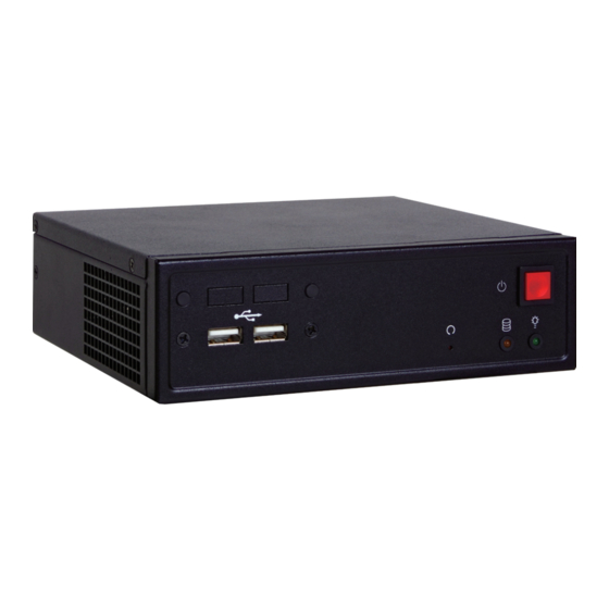
Page 8: Getting The Know The Es520-Hu
Chapter 1 Getting to Know the ES520-HU Front View Rear View HDMI Power DC-in USB 2.0 Reset Power LED USB 3.0 HDD LED Mic-in Line-out Power COM Ports Press to power-on or power-off the system. Used to connect serial devices. -
Page 9: Mechanical Dimensions
Chapter 1 Mechanical Dimensions Chassis Dimensions Motherboard Dimensions Rear View DC 12V 19.85 29.93 35.95 77.95 98.4 Left View Right View 166.00 Front View Chapter 1 Introduction www.dfi.com... -
Page 10: Chapter 2 - Getting Started
Installing the Drivers The system package includes a CD disk. The CD includes drivers that must be installed to pro- vide the best system performance. Refer to the Supported Software chapter for instructions on installing the drivers. Chapter 2 Getting Started www.dfi.com... -
Page 11: Chapter 3 - Installing Device
4. 2 Mini PCIe slots, the SODIMM socket and the SIM card socket are readily accessible after removing the chassis cover. Mounting screws SATA drive Mini PCIe Mini PCIe SIM card socket HDD bracket SODIMM socket Chapter 3 Installing the Device www.dfi.com... - Page 12 4. After completing steps above, fasten the cover with 5 mounting screws. SATA drive Mounting screw HDD bracket Mounting screw 3. Connect the SATA data cable and the SATA power cable to the connectors on the SATA drive. SATA data cable SATA power cable Chapter 3 Installing the Device www.dfi.com...
-
Page 13: Installing The Sodimm
4. Press the memory module down until the clips at each end of the socket lock into position. the socket in one direction only. You will hear a distinctive “click”, indicating the module is correctly locked into the socket. Clip Clip Chapter 3 Installing the Device www.dfi.com... -
Page 14: Installing A Sim Card
1. The SIM card socket is located on the system board. SIM card socket SIM card 4. Close the SIM card cover and lock the 2. Press the SIM card cover backward slightly to release it. press backward release SIM card cover SIM card Chapter 3 Installing the Device www.dfi.com... -
Page 15: Installing Mini Pcie And/Or Msata Cards
4. Press the Mini PCIe card down and use the mounting screw provided to secure the half size or full size card on the system board. Half length Full length Mounting Screw Mounting Screw half size card full size card Chapter 3 Installing the Device www.dfi.com... -
Page 16: Chapter 4 - Jumper Settings
2. Set JP1 pins 2 and 3 to On. Wait for a few seconds and set JP1 back to its default setting, pins 1 and 2 On. 3. Now plug the power cord and power-on the system. Chapter 4 Jumper Settings www.dfi.com... -
Page 17: Usb Power Select
If you are using the Wake-On-USB Keyboard/Mouse function for 2 USB ports, the +5V_standby power source of your power supply must support ≥1.5A. For 3 or more USB ports, the +5V_standby power source of your power supply must support ≥2A. Chapter 4 Jumper Settings www.dfi.com... -
Page 18: Chapter 5 - Ports And Connectors
The Wake-On-USB Keyboard/Mouse function allows you to use a USB keyboard or USB mouse to wake up a system from the S3 (STR - Suspend To RAM) state. To use this function: • Jumper Setting JP25 must be set to “2-3 On: +5V_standby”. Refer to “USB Power Select” in chapter 4 for more information. Important: If you are using the Wake-On-USB Keyboard/Mouse function for 2 USB ports, the +5V_standby power source of your power supply must support ≥1.5A. For 3 or more USB ports, the +5V_standby power source of your power supply must support ≥2A. Chapter 5 Ports and Connectors www.dfi.com... -
Page 19: 12V Dc-In
DC power cord to this jack. We only provide 12V power adapter in the optional package contents. Using a voltage more than the recommended range may fail to boot the system or cause damage to the system board. Chapter 5 Ports and Connectors www.dfi.com... -
Page 20: Graphics Interfaces
TV that has the HDMI port. The LAN ports allow the system board to connect to a local area network by means of a network hub. Driver Installation BIOS Setting Install the graphics driver. Refer to chapter 8 for more information. Configure the onboard LAN in the Chipset menu (“PCH-IO Configuration” submenu) of the BIOS. Refer to chapter 7 for more information. Driver Installation Install the LAN drivers. Refer to chapter 8 for more information. Chapter 5 Ports and Connectors www.dfi.com... -
Page 21: Usb Ports
USB port cables to a connector. BIOS Setting Configure the onboard USB in the Advanced menu (“USB Configuration” submenu) of the BIOS. Refer to chapter 7 for more information. Chapter 5 Ports and Connectors www.dfi.com... -
Page 22: I/O Connectors
Digital I/O Connector The front audio connector allows you to connect to the second line-out and mic-in jacks that are at the front panel of your system. Pins Function Driver Installation DIO7 Install the audio driver. Refer to the chapter 8 for more information. DIO6 DIO5 DIO4 DIO3 DIO2 DIO1 DIO0 Chapter 5 Ports and Connectors www.dfi.com... -
Page 23: Com (Serial) Ports
BIOS. Refer to the chapter 7 for more information. Pin Pin Assignment Pin Pin Assignment HDD Power LED Power Note: HDD-LED To make the RS485 auto flow control function work on COM 1, please set either 8 Signal LED Power PWR-LED data bits + 1 stop bit or one of the following settings: Ground Signal (1) 8 data bits + 1 parity bit + 1 stop bit (2) 8 data bits + 1 parity bit + 2 stop bits RST Signal Ground RESET-SW (3) 8 data bits + 2 stop bits PWR-BTN N.C. Signal Chapter 5 Ports and Connectors www.dfi.com... -
Page 24: Sata (Serial Ata) Connectors
ATA data cable to a SATA connector and the other end to your Serial ATA device. BIOS Setting Configure the Serial ATA drives in the Advanced menu (“SATA Configuration” submenu) of the BIOS. Refer to chapter 7 for more information. Chapter 5 Ports and Connectors www.dfi.com... -
Page 25: Expansion Slots
CPU and system board components. The SIM slot on the system board is used to insert a SIM card. BIOS Setting The Advanced menu (“NCT6106D HW Monitor” submenu) of the BIOS will display the current speed of the cooling fans. Refer to chapter 7 for more information. Chapter 5 Ports and Connectors www.dfi.com... -
Page 26: Smbus Connector
When the system’s power is off and a chassis intrusion occurred, the alarm will sound only when the system restarts. Chapter 5 Ports and Connectors www.dfi.com... -
Page 27: Standby Power Led
Battery The lithium ion battery powers the real-time clock and CMOS memory. It is an auxiliary source of power when the main power is shut off. Safety Measures • Danger of explosion if battery incorrectly replaced. • Replace only with the same or equivalent type recommend by the manufacturer. • Dispose of used batteries according to local ordinance Chapter 5 Ports and Connectors www.dfi.com... -
Page 28: Chapter 6 - Mounting Option
Please refer to the provided DVD for details relevant to the system board. 1. The mounting holes are located at the bottom of the system. 3. Mount the whole system on the wall by fastening the screws through the mounting holes. Mounting hole Chapter 6 Mounting Options www.dfi.com... - Page 29 Chapter 6 182.60 Ø8.50 5.00 182.60 Ø8.50 5.00 Chapter 6 Mounting Options www.dfi.com...
-
Page 30: Chapter 7 - Bios Setup
When ““ appears on the left of a particular field, it indicates that a submenu which contains additional options are available for that field. To display the submenu, move the highlight to that field and press <Enter>. Chapter 7 BIOS Setup www.dfi.com... -
Page 31: Main
The time format is <hour>, <minute>, <second>. The time is based on the 24-hour military-time clock. For example, 1 p.m. is 13:00:00. Hour displays hours from 00 to 23. Minute displays minutes from 00 to 59. Second displays seconds from 00 to 59. Chapter 7 BIOS Setup www.dfi.com... - Page 32 Selects the highest ACPI sleep state the system will enter when the Suspend button is pressed. S3 only (STR) Enables the Suspend to RAM. S3 available for OS to choose from Resume by RTC Alarm When Enabled, the system uses the RTC to generate a wakeup event. Chapter 7 BIOS Setup www.dfi.com...
- Page 33 Number of cores to enable in each processor package. Limit CPUID Maximum Disabled for Windows XP. Intel Virtualization Technology When this field is set to Enabled, the VMM can utilize the additional hardware capabili- ties provided by Vanderpool Technology. Chapter 7 BIOS Setup www.dfi.com...
- Page 34 This field is used to enable or disable the serial ATA port. Enter: Select +/ -: Change Opt. General Help Previous Values Optimized Defaults Save & Exit ESC: Exit Version 2.15.1236. Copyright (C) 2012 American Megatrends, Inc. Chapter 7 BIOS Setup www.dfi.com...
- Page 35 Enables or disables the rapid start display save or restore. Version 2.15.1236. Copyright (C) 2012 American Megatrends, Inc. Intel AMT Enables or disables the AMT function. Hide Un-Configure ME Confirmation OEMFlag Bit 6: Hide Un-configure ME without the password confirmation prompt. Chapter 7 BIOS Setup www.dfi.com...
- Page 36 EHCI driver. Select Screen → ←: Select Item ↑↓: Enter: Select +/ -: Change Opt. General Help Previous Values Optimized Defaults Save & Exit ESC: Exit Version 2.15.1236. Copyright (C) 2012 American Megatrends, Inc. Chapter 7 BIOS Setup www.dfi.com...
- Page 37 +/ -: Change Opt. Save & Exit General Help ESC: Exit Previous Values Optimized Defaults Save & Exit Version 2.15.1236. Copyright (C) 2012 American Megatrends, Inc. ESC: Exit Version 2.15.1236. Copyright (C) 2012 American Megatrends, Inc. Chapter 7 BIOS Setup www.dfi.com...
- Page 38 Boundary 1 General Help Speed Count 5 Previous Values Speed Count 4 Optimized Defaults Speed Count 3 Save & Reset Speed Count 2 ESC: Exit Speed Count 1 Version 2.15.1236. Copyright (C) 2012 American Megatrends, Inc. Chapter 7 BIOS Setup www.dfi.com...
- Page 39 If the system’s power is off when AC power failure occurs, it will remain off when power returns. If the system’s power is on when AC power failure occurs, the system will power-on when power returns. Chapter 7 BIOS Setup www.dfi.com...
- Page 40 Ipv6 PXE Support [Enabled] Select Screen → ←: Select Item ↑↓: Enter: Select +/ -: Change Opt. General Help Previous Values Optimized Defaults Save & Exit ESC: Exit Version 2.15.1236. Copyright (C) 2012 American Megatrends, Inc. Chapter 7 BIOS Setup www.dfi.com...
-
Page 41: Chipset
System Agent (SA) Configuration Select Screen → ←: Select Item ↑↓: Enter: Select +/ -: Change Opt. General Help Previous Values Optimized Defaults Save & Exit ESC: Exit Version 2.15.1236. Copyright (C) 2012 American Megatrends, Inc. Chapter 7 BIOS Setup www.dfi.com... - Page 42 Version 2.15.1236. Copyright (C) 2012 American Megatrends, Inc. Version 2.15.1236. Copyright (C) 2012 American Megatrends, Inc. XHCI Mode Selects the operation mode of the XHCI controller. The options are Smart Auto, Auto, En- abled, Disabled and Manual. Chapter 7 BIOS Setup www.dfi.com...
- Page 43 256M 512M 1024M Select Screen → ←: Select Item ↑↓: Enter: Select +/ -: Change Opt. General Help Previous Values Optimized Defaults Save & Exit ESC: Exit Version 2.15.1236. Copyright (C) 2012 American Megatrends, Inc. Chapter 7 BIOS Setup www.dfi.com...
- Page 44 Select Screen → ←: Select Item ↑↓: Enter: Select +/ -: Change Opt. General Help Previous Values Optimized Defaults Save & Exit ESC: Exit Version 2.15.1236. Copyright (C) 2012 American Megatrends, Inc. Chapter 7 BIOS Setup www.dfi.com...
-
Page 45: Boot
When set to Off, the function of the numeric keypad is the arrow keys. Controls the execution of UEFI and legacy PXE OpROM. Quiet Boot Launch Storage OpROM policy Enables or disables the quiet boot function. Controls the execution of UEFI and legacy storage OpROM. Chapter 7 BIOS Setup www.dfi.com... -
Page 46: Security
<Enter>. A dialog box will appear. Select Yes to restore the default values of all the setup options. Launch EFI Shell from filesystem device Attempts to Launch EFI Shell application (Shellx64.efi) from one of the available filesystem devices. Chapter 7 BIOS Setup www.dfi.com... -
Page 47: Notice: Bios Spi Rom
Writing NVRAM ...... done technical person's instructions to confirm that the MAC address should be burned Verifying NVRAM ....done or not. Erasing BootBlock ....done Writing BootBlock ....done Verifying BootBlock ....C:\AFU\AFUDOS> Chapter 7 BIOS Setup www.dfi.com... -
Page 48: Chapter 8 - Supported Software
CD, “Autorun” did not automatically start (which is, the Mainboard Utility CD screen did not appear), please go directly to the root directory of the CD and double-click “Setup”. Auto Run Page (For Windows 8.1) Chapter 8 Supported Software www.dfi.com... -
Page 49: Intel Chipset Software Installation Utility
To install the utility, click “Intel Chipset Software Installation Utility” on the main menu. 1. Setup is now ready to install the utility. Click Next. 4. After completing installation, click Finish to exit setup. 2. Read the license agreement then click Yes. Chapter 8 Supported Software www.dfi.com... - Page 50 We recommend that you skip this process by disabling this function then click Next. 2. Read the license agreement then click Yes. 5. Click “Yes, I want to restart this computer now” then click Finish. Restarting the system will allow the new software installation to take effect. Chapter 8 Supported Software www.dfi.com...
- Page 51 To install the driver, click “Intel Management Engine Drivers 9.5” on the main menu. 1. Setup is ready to install the driver. Click Next. 4. After completing installation, click Finish. 2. Read the license agreement then click Yes. Chapter 8 Supported Software www.dfi.com...
- Page 52 Finish. then click “Next”. Restarting the system will allow the new software installation to take effect. 3. Select the program features you want installed then click Next. Chapter 8 Supported Software www.dfi.com...
- Page 53 DFI Utility 4. Click Install to begin the installation. DFI Utility provides information about the board, Watchdog, DIO, and Backlight. To access the utility, click “DFI Utility” on the main menu. Note: If you are using Windows 7, you need to access the operating system as an administrator to be able to install the utility.
- Page 54 Chapter 8 The DFI Utility icon will appear on the desktop. Double-click the icon to open the utility. 3. Enter “User name” and “Organization” information then click “Next”. 4. Click “Install” to begin the installation. Information 5. After completing installa tion, click “Finish”.
- Page 55 Chapter 8 HW Health Set WatchDog Chapter 8 Supported Software www.dfi.com...
- Page 56 3. After completing installation, click Finish. To install the utility, click “Microsoft Framework 4.5” on the main menu. 1. Read and accept the license agree- ment. Then, click “Installation“. 2. Setup is installing the driver. Chapter 8 Supported Software www.dfi.com...
- Page 57 1. Setup is ready to install the driver. Click Next. 4. Setup is currently installing the driver. After installation has com- pleted, click Next. 2. Read the license agreement then click Yes. 5. After completing installation, click Finish. Chapter 8 Supported Software www.dfi.com...
- Page 58 1. Setup is now ready to install the utility. Exit all programs before continuing and click Next to continue. 4. Click Finish to complete the setup process. 2. Read the license agreement and then click Yes. Chapter 8 Supported Software www.dfi.com...
-
Page 59: Intel Rapid Storage Technology
Click Next. 4. Go through the readme document for system requirements and instal- lation tips then click Next. 2. Read the warning then click Yes. 5. Setup is now installing the utility. Click Next to continue. Chapter 8 Supported Software www.dfi.com... -
Page 60: Intel Rapid Start Technology
1. Setup is now ready to install the utility. Click Next. 2. Click ON and select the Advanced Settings to enable the Intel Rapid Start Technology. Then, click Save. Chapter 8 Supported Software www.dfi.com... - Page 61 Select a setup type and then click Next. The setup program is now ready to install the utility. Click Next. Click Install. Click “I accept the terms in the license agreement” and then click “Next”. Chapter 8 Supported Software www.dfi.com...
- Page 62 TPM requires installing the Microsoft 10. Click “Yes“ to restart your system. Visual C++ package prior to install- ing the utility. Click Install. The setup program is currently installing the Microsoft Visual C++ package. Click Finish. Chapter 8 Supported Software www.dfi.com...
- Page 63 To install the reader, click “Adobe Acrobat Reader 9.3” on the main menu. 1. Click Next to install or click Change Destination Folder to select another folder. 2. Click Install to begin installa- tion. 3. Click Finish to exit installation. Chapter 8 Supported Software www.dfi.com...
-
Page 64: Chapter 9 - Intel Amt Settings
SPI device. Select Screen → ←: Select Item ↑↓: Enter: Select +/ -: Change Opt. General Help Previous Values Optimized Defaults Save & Exit ESC: Exit Version 2.15.1236. Copyright (C) 2012 American Megatrends, Inc. Chapter 9 Intel AMT Settings www.dfi.com... -
Page 65: Enable Intel ® Amt In The Intel ® Management Engine Bios
Copyright(C) 2003-13 Intel Corporation. All Rights Reserved. MAIN MENU MEBx Login > Intel (R) ME General Settings > Intel (R) AMT Configuration MEBx Exit Intel(R) ME Password [↑↓] = Move Highlight [Enter] = Select Entry [Esc]= Exit Chapter 9 Intel AMT Settings www.dfi.com... - Page 66 Intel(R) Management Engine BIOS Extension v9.0.0.0029/Intel(R) ME v9.5.30.1808 Copyright(C) 2003-13 Intel Corporation. All Rights Reserved. MAIN MENU > Intel (R) ME General Settings > Intel (R) AMT Configuration MEBx Exit [↑↓] = Move Highlight [Enter] = Select Entry [Esc]= Exit Chapter 9 Intel AMT Settings www.dfi.com...
- Page 67 > SOL/ IDER/ KVM > User Consent Password Policy <Anytime> > Network Setup Unconfigure Network Access <Full Unprovision> > Remote Setup And Configuration > Power Control [↑↓] = Move Highlight [Enter] = Select Entry [Esc]= Exit Chapter 9 Intel AMT Settings www.dfi.com...
- Page 68 Legacy Redirection Mode <Disabled> Legacy Redirection Mode <Disabled> Disabled Enabled Menu for FW Redirection Configuration [↑↓] = Move Highlight [Enter] = Select Entry [Esc]= Exit [↑↓] = Move Highlight [Enter] = Complete Entry [Esc]= Discard Changes Chapter 9 Intel AMT Settings www.dfi.com...
- Page 69 Legacy Redirection Mode <Disabled> Legacy Redirection Mode <Disabled> Disabled Disabled Enabled Enabled [↑↓] = Move Highlight [Enter] = Complete Entry [Esc]= Discard Changes [↑↓] = Move Highlight [Enter] = Complete Entry [Esc]= Discard Changes Chapter 9 Intel AMT Settings www.dfi.com...
- Page 70 > Remote Setup And Configuration > Power Control Default Password Only During Step And Configuration Anytime [↑↓] = Move Highlight [Enter] = Complete Entry [Esc]= Discard Changes [↑↓] = Move Highlight [Enter] = Complete Entry [Esc]= Discard Changes Chapter 9 Intel AMT Settings www.dfi.com...
- Page 71 Domain Name > TCP/ IP Settings Shared/ Dedicated FQDN <Shared> Dynamic DNS Update <Disabled> Computer Domain Name [Enter] = Complete Entry [Esc]= Discard Changes [↑↓] = Move Highlight [Enter] = Select Entry [Esc]= Exit Chapter 9 Intel AMT Settings www.dfi.com...
- Page 72 Shared/ Dedicated FQDN <Shared> Dynamic DNS Update <Disabled> Disabled Enabled Disabled Enabled [↑↓] = Move Highlight [Enter] = Complete Entry [Esc]= Discard Changes [↑↓] = Move Highlight [Enter] = Complete Entry [Esc]= Discard Changes Chapter 9 Intel AMT Settings www.dfi.com...
- Page 73 Provision Record is not present > Remote Setup And Configuration > Power Control [ESC] = Exit [↑↓] = Move Highlight [Enter] = Select Entry [Esc]= Exit [↑↓] = Move Highlight [Enter] = Select Entry [Esc]= Exit Chapter 9 Intel AMT Settings www.dfi.com...
- Page 74 Mobile: ON in S0 Mobile: ON in S0, ME Wake in S3, S4-5 (AC only) Exit [↑↓] = Move Highlight [Enter] = Complete Entry [Esc]= Discard Changes [↑↓] = Move Highlight [Enter] = Select Entry [Esc]= Exit Chapter 9 Intel AMT Settings www.dfi.com...
-
Page 75: Appendix A - Watchdog Sample Code
;Select watchdog timer register DX,AL DX,2FH AL,10H ;Set watchdog timer value DX,AL DX,2EH AL, F5H ;Select watchdog Control Register DX,AL DX,2FH AL,61H ;Set Watchdog Control Value DX,AL ;---------------------------------------------------------------- ;(1) Exit extended function mode ;---------------------------------------------------------------- DX,2EH AL,AAH DX,AL Appendix A Watchdog Sample Code www.dfi.com... -
Page 76: Appendix B - System Error Message
The BIOS reports memory test fail if the memory has error(s). VIDEO selection. FLOPPY DISK(S) fail (80) Unable to reset floppy subsystem. FLOPPY DISK(S) fail (40) Floppy type mismatch. Hard Disk(s) fail (80) HDD reset failed. Hard Disk(s) fail (40) HDD controller diagnostics failed. Appendix B System Error Message www.dfi.com... -
Page 77: Appendix C - Troubleshooting
4. There is not enough space left on the diskette. Use another diskette with adequate storage 4. Adjust the brightness of the display by turning the monitor’s brightness control knob. space. Appendix C Troubleshooting Checklist www.dfi.com... -
Page 78: Hard Drive
Nothing happens when a key on the keyboard was pressed. 1. Make sure the keyboard is properly connected. 2. Make sure there are no objects resting on the keyboard and that no keys are pressed dur- ing the booting process. Appendix C Troubleshooting Checklist www.dfi.com...
Need help?
Do you have a question about the ES520-HU and is the answer not in the manual?
Questions and answers