
Subscribe to Our Youtube Channel
Related Manuals for Vello FWIRC-N


Summary of Contents for Vello FWIRC-N
- Page 1 FREEWAVE IR COMMANDER WIRELESS INFRARED TTL FLASH TRIGGER FOR NIKON i-TTL (FWIRC-N) USER MANUAL...
- Page 2 THANK YOU FOR CHOOSING VELLO The Vello FWIRC-N FreeWave IR TTL control. It also offers high- Commander is the nexus of your speed sync with compatible flashes, wireless flash setup, enabling you to allowing you to use shutter speeds set and control all functions of your higher than your camera’s top flash...
-
Page 3: Table Of Contents
TABLE OF CONTENTS Precautions ............ 4 Turning On the FreeWave Advanced Features ........23 IR Commander ........... 12 High-Speed Sync Mode ������������������������������������� 23 Key Features ..........6 Repeating (Stroboscopic) Mode ������������������ 23 Selecting Channels ........14 The Modeling Light ���������������������������������������������� 25 Overview ............ -
Page 4: Precautions
• Keep this product away from water, cause a malfunction. Promptly remove moisture, and any flammable gases the batteries and contact Vello • Dispose of used or damaged batteries or liquids. Customer Service. according to local regulations. - Page 5 • Keep the metal contacts in the • Do not clean this product with agents battery compartment clean and free containing corrosive or flammable of corrosion and dirt. Do not touch substances. them with your fingers. Corrosive elements on the contacts can damage •...
-
Page 6: Key Features
KEY FEATURES 180° rotation: Pivots to Manual mode: Can manually adjust Modeling light: Gives the appearance achieve IR line of sight. power output in 1/3 increments. of a continuous light to simulate the direction of light. Wireless i-TTL (intelligent Standby mode: through-the-lens): Makes Flash Exposure Bracketing: Reduces power consumption. -
Page 7: Overview
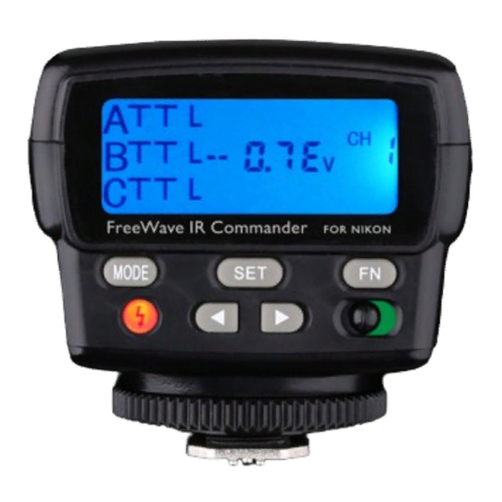
OVERVIEW Front 1. Battery chamber 2. AF-assist light 3. Transmitter 4. Locking wheel 5. Mounting foot 6. LCD 7. Mode button 8. Test button/flash ready light [ ] Back 9. Navigation buttons [ 10. Set button 11. FN button 12. Power switch Also Included •... -
Page 8: Compatible Devices
COMPATIBLE DEVICES INSTALLING BATTERIES The Vello FWIRC-N FreeWave IR The FreeWave IR Commander is Commander is compatible with powered by two AA batteries. To Nikon’s i-TTL (intelligent through- install batteries, make sure the device the-lens) system. To make full use of... -
Page 9: Setting Up Slave Flash Units
SETTING UP SLAVE FLASH UNITS You can create a sophisticated lighting To set up your slave flash units: setup by positioning slave flash units individually or in groups to function 1. Turn on your slave flash and set it to as main, fill, accent, and other lights. - Page 10 When positioning wireless slaves to light • Make sure the Commander’s a subject, keep in mind the following: transmitter is facing your flash’s IR sensor and that there are no obstructions between the two units (see Turning On the FreeWave IR Commander on page 12 for more).
-
Page 11: Mounting The Freewave Ir Commander
MOUNTING THE FREEWAVE IR COMMANDER To mount the FreeWave IR Commander To dismount the FreeWave IR on your camera, make sure all devices Commander from your camera, are turned off and follow these steps: make sure the Commander is turned off and follow these steps: 1. -
Page 12: Turning On The Freewave Ir Commander
TURNING ON THE FREEWAVE IR COMMANDER Test Button/Ready Light To turn on the FreeWave IR The ready light indicates the status Commander, slide the power of the Commander. When it glows switch to the On position. When red, the Commander is ready to turning off the Commander, it will be fired. - Page 13 Automatic Power-saving Function LCD Illumination After a designated period of inactivity, When reactivating via your camera’s When you turn on the FreeWave IR the Commander will automatically shutter button, standby time will Commander or press any button, the enter power-saving mode to conserve be controlled by the camera’s LCD will glow blue for up to six seconds.
-
Page 14: Selecting Channels
SELECTING CHANNELS Lock Mode To prevent inadvertent operation of On the FreeWave IR Commander, the Commander, you can deactivate its four channels (1, 2, 3, and 4) are controls by setting it to lock mode. This available. You can use this option will disable all of the buttons except for to prevent your flashes from being the power switch and the test button. -
Page 15: About Flash Groups
ABOUT FLASH GROUPS On the FreeWave IR Commander, Note: Be aware of the independent three flash groups (A, B, and C) are recycling time of each flash to ensure available, with independent control all flash units are ready to fire. over all three groups. -
Page 16: I-Ttl Mode
i-TTL MODE In i-TTL mode, the FreeWave IR Setting i-TTL mode: To set a group Commander will automatically set to i-TTL mode, follow these steps: the appropriate flash level via your 1. Press the Set button repeatedly until camera’s intelligent through-the- lens (i-TTL) metering system data, the desired group’s mode indicator i-TTL Mode... - Page 17 Adjusting a Flash Group’s TTL Power (EV) To adjust EV: Flash output compensation (EV) can be set in i-TTL and AA modes (for more 1. Make sure the desired group is in information about AA, refer to AA i-TTL mode. Mode on page 18).
-
Page 18: Auto Aperture Mode
AUTO APERTURE MODE Setting AA Mode In Auto Aperture (AA) mode, your To set a group to AA mode, flash’s built-in sensor will automatically follow these steps: set the appropriate flash power output 1. Press the Set button repeatedly until level by measuring the reflected light from the environment. - Page 19 Adjusting a Flash Group’s TTL Power (EV) To adjust EV: Flash output compensation (EV) can be set in i-TTL and AA modes (for more 1. Make sure the desired group is in information about i-TTL, refer to i-TTL AA mode. Mode on page 16).
-
Page 20: Manual Mode
MANUAL MODE Setting Manual Mode For greater creative control over To set a group to manual your images, you can set the flash mode, follow these steps: power output level manually. 1. Press the Set button repeatedly until Manual mode and flash power output the desired group’s mode indicator Manual Mode are set independently for each group. - Page 21 Adjusting Power Output Flash power output is represented as a To adjust power output: fraction. The 1/1 setting is the full-power flash, and each successive setting halves 1. Make sure the desired group is in the light output, all the way down to manual mode.
-
Page 22: Restoring The Factory Settings
RESTORING THE FACTORY SETTINGS This restores the FreeWave IR Commander to the factory default settings. This will erase all current settings and replace them with the default settings. Default Screen To restore the factory settings, press and hold the Set button for five seconds until the Commander reverts to the default screen. -
Page 23: Advanced Features
ADVANCED FEATURES High-Speed Sync Mode Repeating (Stroboscopic) Mode You can use shutter speeds that are The repeating (stroboscopic) mode faster than your camera’s maximum fires the flash multiple times in quick flash sync speed with the FreeWave succession during a single exposure. In IR Commander by enabling high-speed stroboscopic mode, you can adjust flash sync (HSS) in your camera. - Page 24 To set the FreeWave IR Commander to 4. Press the Set button repeatedly until stroboscopic mode, follow these steps: the flash output level blinks, and use the Left and Right [ ] navigation 1. Mount the Commander on your buttons to adjust the output from camera.
-
Page 25: The Modeling Light
The Modeling Light Autofocus Assist The modeling light gives the appearance Camera autofocus (AF) systems can To enable AF assist on the Commander, of a continuous light so you can have difficulty locking onto a subject press the FN button. The AF-ILL approximate how the flash will illuminate in dim light or low-contrast scenes. -
Page 26: Flash Exposure Bracketing
Flash Exposure Bracketing Flash Value Lock Flash exposure bracketing (FEB) lets In i-TTL mode, you can lock the flash you take three continuous pictures output level that is optimal for specific while automatically changing the flash elements of your scene by using the flash exposure compensation between value lock (FV Lock) feature. -
Page 27: Specifications
SPECIFICATIONS Transmission Infrared Transmission Range Up to 90´ (27.5 m) Channels Groups Horizontal: 40° Flash Coverage Vertical: 30° Display Backlit LCD Controllable Remote Flash Mode i-TTL, AA, Manual, Stroboscopic Power Source Two AA batteries Dimensions 2.5˝ × 2.5˝ × 3.3˝ (6.3 × 6.3 × 8.3 cm) Weight 4.2 oz. -
Page 28: Troubleshooting
TROUBLESHOOTING The Commander is stuck The Commander is not flashing. The slave units are not firing. in the camera hot shoe. • Make sure that fresh batteries • Make sure the hot-shoe light’s locking • Make sure that the mounting foot are installed and in the proper switch is set to the lock position. - Page 29 • Make sure that the Commander is • Make sure that the electrical contacts Note: After changing any settings in your within the transmission range and on the foot of the slave unit are not wireless setup, press the test button to fire the wireless sensor on the slave is dirty.
- Page 30 ONE-YEAR LIMITED WARRANTY This VELLO product is warranted to the original purchaser to be free from defects in materials and workmanship under normal consumer use for a period of one (1) year from the original purchase date or thirty (30) days after replacement, whichever occurs later.
- Page 31 To obtain warranty coverage, contact the Vello Customer Service Department to obtain a return merchandise authorization (“RMA”) number, and return the defective product to Vello along with the RMA number and proof of purchase. Shipment of the defective product is at the purchaser’s own risk and expense.
- Page 32 VELLO is a registered trademark of the Gradus Group. © 2015 Gradus Group LLC. All Rights Reserved. www.vellogear.com All other trademarks are the property of their respective owners.
Need help?
Do you have a question about the FWIRC-N and is the answer not in the manual?
Questions and answers