Advertisement
Quick Links
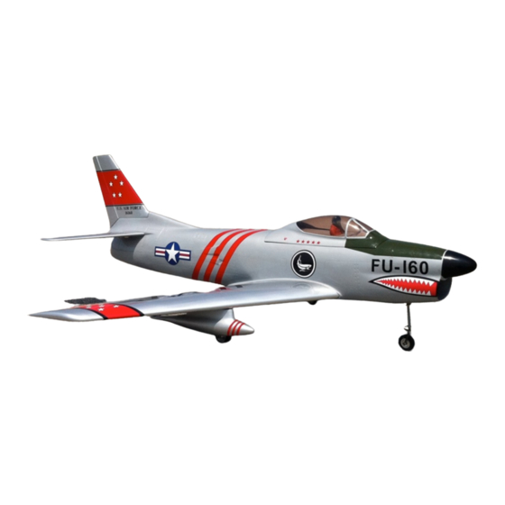
Wing Span
Wing Area
Flying Weight
Fuselage Length
Engine
Recommended Engine
The F86D is designed for maximum performance. If you are not
familiar with the operation of turbine powered aircraft please
seek the advice of an experienced modeler. Operating this
model with out prior preparation and experience can cause
injuries.
Specifications
Warning!!! This is not a toy.
60in.
895 sq in.
15 lb.
68 in.
12lb.-18lb. Thrust Turbine
Jet Cat P60, KingTech K80
Advertisement

Related Manuals for Troy Built Models F86D DOG SABRE


Summary of Contents for Troy Built Models F86D DOG SABRE
- Page 1 Specifications Wing Span 60in. Wing Area 895 sq in. Flying Weight 15 lb. Fuselage Length 68 in. Engine 12lb.-18lb. Thrust Turbine Recommended Engine Jet Cat P60, KingTech K80 Warning!!! This is not a toy. The F86D is designed for maximum performance. If you are not familiar with the operation of turbine powered aircraft please seek the advice of an experienced modeler.
-
Page 2: Before You Begin
Before You Begin 1. Read through the instruction manual thoroughly before beginning construction 2. Check all parts supplied with the kit for defects, and missing parts. Dry fit all parts that will be glued for proper fit. If any parts are found to be defective please contact your local dealer or us directly for assistance. - Page 3 Locate the plastic hinges with pin and fit into slots that are cut into the wing panels, trim the slot as necessary. Hinge the ailerons and flaps on each wing panel using Hysol or 30 min epoxy. (NOTE: If you are using a larger engine, like the K80, install the flap hinges at the bottom edge of the flap so greater flap throw can be obtained).
- Page 4 Locate 4 composite control horns and cut a slot in each aileron and flap for the control horn. Use 30 min epoxy or Hysol to secure horn in place and let cure. Assemble a pushrod using 2 clevisʼs and and secure to the servo. Pay close attention to have a slop free surface;...
- Page 5 Assemble a pushrod using 2 clevisʼs and and secure to servo. Pay close attention to have a slop free surface. Any excess movement can cause flutter during high speed flight.
- Page 6 Locate the servo location in the rudder and glue blocks inside of the rudder to attach the servo with 90 degree servo mounts ( not supplied ). We recommend you use a Hitec HS-5245MG. After you complete the above assembly, drill two holes in the fuselage where the vertical stabilizer retention pins will fit into.
- Page 7 Locate the two horizontal stabilizer halves and prepare the surfaces to hinge. Find the plastic hinges with pin and fit into the slots that are cut into the elevators, trim the slots as necessary. Hinge the elevators on each panel using Hysol or 30 min epoxy. The elevator servoʼs are installed just like the ones in the rudder except for the servo cover, which is held on with clear tape for best utilization of space in the servo bay.
- Page 8 We now have to glue the two horizontal stabilizers to the fuselage. Locate the two carbon fiber spars for the horizontal stabilizer and test fit them into the fuselage. DO NOT change the hole location, it is critical due to precise stab incidents.
- Page 9 Before installing the turbine run all wires from the tail along the top of the fuselage. Use either aluminum tape or heat shield to guard the wires from the heat. Slide the dual walled exhaust pipe into the fuselage. Trim the rear of the fuselage (primarily on the bottom) to allow the thrust pipe to exit the fuselage with only a small gap all around.
- Page 10 After you have test fit the turbine and the thrust pipe glue the ply former in place with Hysol or 30 min epoxy with micro balloons and use two sheet metal screws to affix the thrust pipe to the former. 12.
- Page 11 15. Install a mini-servo for steering, we recommend a Hitec HS225MG. Locate the supplied pull-pull cable and install the steering cables as per the retract instructions supplied with the kit. Do not over tighten the cables since this will cause the nose gear to have problems locking in the down position.
- Page 12 Installation of the hatch and canopy is very simple and should not be made harder than it is. Find the supplied hatch latch and glue it to the fiberglass hatch from the inside. Drill a small hole in the fuselage for the hatch latch pin to fit into.
- Page 13 18. The drop tanks are held in place with two screws in each drop tank. Use two 3mm pan head screws and screw them into the blind nuts in the drop tank. The distance of how far you need to screw them in varies depending on installation, so do not fully secure them yet.
- Page 14 19. Underneath these holes there are needed supports for the drop tanks. Cut a small square away and place either carbon fiber or hard wood and glue it in place.
- Page 15 20. Control Throws and CG Ailerons- 15mm up 15mm down measured at wing tip Elevator- 26mm up 26mm down measured at the root Rudder- 30mm left 30mm right Flaps- 25mm down for take-off 45mm down for landing measured at wing root Crow- 12mm up on each Aileron with landing flaps measured at wing tip.
-
Page 16: First Flight
FIRST FLIGHT If this is your first turbine powered model we suggest you seek the help of an experienced RC Jet Pilot for the maiden flight of your model. Before starting the turbine, ensure you have all safety equipment in place incase of a fire or other problem.
Need help?
Do you have a question about the F86D DOG SABRE and is the answer not in the manual?
Questions and answers