Table of Contents
Advertisement
Quick Links
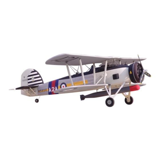
FAIREY SWORDFLSH
Specification:
Length
:1700 mm(67")
Wing Span
:2160 mm(85.4")
Wing Area
:129/sq. dm
13.9/sq.ft
Wing Loading :69.8g/sq. dm
22.8oz/sq. ft
Flying Weight :9000g(19.8 lbs)
Radio
:6ch & 7servos
Engine(a pair) :180 4-cycle
SAFETY PRECAUTIONS
INSTRUCTION MANUAL
This R/C airplane is not a toy!
(The people under 18 years old is forbidden from flying this model)
First-time builders should seek advice from people having building
experience.If misused or abused,it can cause serious bodily injury
and damage to property.
Fly only in open areas and preferably at a dedicated R/C flying site.
We suggest having a qualified instructor carefully inspect your
airplane before its first flight.Please carefully read and follow all
instructions included with this airplane,your radio control system
and any other components purchased separately.
Advertisement
Table of Contents

Subscribe to Our Youtube Channel
Related Manuals for Troy Built Models FAIREY SWORDFLSH


Summary of Contents for Troy Built Models FAIREY SWORDFLSH
-
Page 1: Instruction Manual
FAIREY SWORDFLSH Specification: Length :1700 mm(67") Wing Span :2160 mm(85.4") Wing Area :129/sq. dm 13.9/sq.ft Wing Loading :69.8g/sq. dm 22.8oz/sq. ft Flying Weight :9000g(19.8 lbs) INSTRUCTION MANUAL Radio :6ch & 7servos Engine(a pair) :180 4-cycle This R/C airplane is not a toy! -
Page 2: Side View
Adjustment. Adjustment. (with 7 servos), Side View Side View AILERON 20mm 20mm RUDDER 25mm 6 channel radio for aiplane is highly recommended for this model. AILERON 25mm Top view AILERON Centre of Gravity. : 4-cycle .180 Spinner nut " 130mm Apply Pre-cover the covering with clean cloth! Warning... -
Page 3: Accessory List For The Coming Installation Steps
Drill holes to relevant position on the fuselage and Trim the dummy radiator careful along the shaded line Assemble the aileron to main wing with instant Accessory list for the coming installation steps. epoxy the dummy bomb in it steadily. and epoxy it to relevant position on the fuselage. - Page 4 Secure the servo.Install the nylon control horn and Keep about 1mm width space between aileron Epoxy the dummy engine to appropriate position Cut the surplus portion off the dummy engine carefully. connect the linkage. and trailing edge. in the cowl. TP Screw (2.3x12mm) TP Screw (3x20mm) Trailing...
- Page 5 According to the rib template drill holes to the top Notice the alignment of the steel wire when assemble it. Assemble the stabilizer strut. Install the nylon control horn and connect the linkage. outer wing and epoxy wood dowel in them. 36mm Screw (3x10mm) Retainer...
- Page 6 According to the rib template drill holes to the bottom Fix the metal plate to the appropriate position steadily Fix another side of the lower wing strut to the fuselage Fix the wings steadily with screw. outer wing and epoxy wood dowel in them. on the bottom of the lower wing.
- Page 7 Set blind nut to appropriate position in the fuselage Fix the top mid wing struts to the fuselage with gear Accessory list for the coming installation steps. and assemble the bottom wings to fuselage with screw Install the servo of switch. plates as illustration.
- Page 8 Down action the center line,drilling holes and set blind Assemble the aluminum block to appropriate position The sketch map of the the push rod assemble Assemble the fiber cover to fuselage with the top nut to the appropriate symmetrical position for on bottom of the top wing with screw.
- Page 9 keep about 1mm width space between stabilizer Put the stabilizer to appropriate position on the fuselage Epoxy ply to appropriate position in the fuselage The side sketch map of the engine installation finished. and drill holes throught the stabilizer and tail fuselage. and elevator.
- Page 10 Drill holes to appropriate position in the tail fuselage and Keep some space about 1mm width between Assemble the linkage rods for elevator and rudder. Install the control horn and connect the linkage. rudder for connecting the rudder and rudder servo. the tailing edge and the rudder.
Need help?
Do you have a question about the FAIREY SWORDFLSH and is the answer not in the manual?
Questions and answers