Table of Contents
Advertisement
Quick Links
1800JN (NG) & 1800JP (LPG)
DANGER
!
A barrier designed to reduce the risk of burns from the hot
viewing glass is provided with this appliance and shall be
installed for the protection of children and other at-risk
individuals.
!
WARNING
FIRE OR EXPLOSION HAZARD
Failure to follow safety warnings exactly
could result in serious injury, death, or
property damage.
— Do not store or use gasoline or other
fl ammable vapors and liquids in the
vicinity of this or any other appliance.
— WHAT TO DO IF YOU SMELL GAS
▪ Do not try to light any appliance.
▪ Do not touch any electrical switch; do
not use any phone in your building.
▪ Leave the building immediately.
▪ Immediately call your gas supplier from
a neighbor's phone. Follow the gas
supplier's instructions.
▪ If you cannot reach your gas supplier,
call the fi re department.
— Installation and service must be
performed by a qualifi ed installer, service
agency or the gas supplier.
4004995-02
©2016, Miles Industries Ltd.
L3 S
DV ZC Gas Fireplace
Installation & Owner's Manual
HOT GLASS WILL
CAUSE BURNS.
DO NOT TOUCH GLASS
UNTIL COOLED.
NEVER ALLOW CHILDREN
TO TOUCH GLASS.
ERIES
Please read this manual
BEFORE installing and
operating this appliance.
This manual contains instructions to install the
ENGINE ONLY. A front or trim kit is REQUIRED
to install the engine. A barrier screen is provided
with the front or trim kit. Refer to the manual
supplied with the front or trim for installation.
This appliance may be installed in an
after-market permanently located,
manufactured (mobile) home where not
prohibited by local codes.
This appliance is only for use with the type
of gas indicated on the rating plate. This
appliance is not convertible for use with
other gases, unless a certifi ed kit is used.
This appliance is a domestic room-heating
appliance. It must not be used for any other
purposes such as drying clothes, etc.
This appliance is suitable for installation in a
bedroom or bed sitting room.
Ce guide est disponible en français sur demande.
I N S TA L L E R
L e a v e t h i s m a n u a l
w i t h t h e a p p l i a n c e .
C O N S U M E R
R e t a i n t h i s m a n u a l
f o r f u t u r e r e f e r e n c e .
Advertisement
Table of Contents

Subscribe to Our Youtube Channel
Related Manuals for Valor 1800JN


Summary of Contents for Valor 1800JN
- Page 1 L3 S ERIES DV ZC Gas Fireplace 1800JN (NG) & 1800JP (LPG) Installation & Owner’s Manual DANGER I N S TA L L E R L e a v e t h i s m a n u a l HOT GLASS WILL w i t h t h e a p p l i a n c e .
-
Page 2: Table Of Contents
fi tter in the State of North Vancouver, BC, CANADA V7H 3B1 Massachusetts. Also, see Carbon Monoxide Tel. 604-984-3496 Fax 604-984-0246 Detector requirements on page 18. www.valorfi replaces.com © Copyright Miles Industries Ltd., 2016. All rights reserved. -
Page 3: Safety Precautions
Safety Precautions READ and UNDERSTAND all instructions carefully Due to the high temperature, the appliance should be before starting the installation. FAILURE TO FOLLOW LOCATED out of traffi c areas and away from furniture these installation instructions may result in possible fi re and draperies. -
Page 4: Safety And Your Fireplace
Child Safety Precautions and Recommendations, A physical barrier is strongly • recommended if there are young Parts of your Valor Fireplace become • children, or at-risk individuals in the extremely hot while in operation. house. Install an approved after- The glass viewing window •... -
Page 5: Owner's Information
For purchasing a Valor by Miles Industries. Your new EXTREMELY HOT!!! radiant gas heater is a technical appliance that must be installed by a qualifi ed dealer. Each Valor fi replace • READ the SAFETY information on pages is fully tested during the production process for your 3 and 4 of this manual BEFORE operating safety and comfort. -
Page 6: Operating Your Fireplace For The First Time
OWNER’S Owner’s Information INFORMATION Operating Your Fireplace for the First Time compromising the strength of the glass. An emulsion type cleaner is recommended. When operating your new fi replace for the fi rst time, • Use a soft damp cloth to apply the cleaner. Dry the some vapors may be released due to the burning of glass with a soft, dry, preferably cotton cloth. - Page 7 WARNING Failure to install the window correctly can leak carbon monoxide, affect the performance of the fi replace, damage components, cause overheating resulting in dangerous conditions. Damage caused by incorrect window installa- tion is not covered by the Valor warranty.
-
Page 8: Checking Pilot And Burner Flames
OWNER’S Owner’s Information INFORMATION The appliance area must always be kept clear and 5. If the Hot Glass Warning plate has been removed from the front lower corner of the window, free from combustible materials, gasoline and other reinstall it by sliding it between the glass and fl... -
Page 9: Using Remote Control Handset Wall Holder
OWNER’S Owner’s Information INFORMATION 2. Disconnect the snap connector Servicing Your Fireplace from the battery holder. Do If any attention is required for your appliance, contact not pull the connector by the your supplier quoting the model number. It will be wire! helpful if the appliance’s serial number can also 3. -
Page 10: How To Ensure Your Fireplace Cannot Be Turned On Inadvertently
OWNER’S Owner’s Information INFORMATION How to Ensure Your Fireplace Cannot Be Turned ON Inadvertently You can use one of the two following methods to ensure that your fi replace will not turn on when you don’t want it on. Battery holder &... -
Page 11: Remote Control Operation
OWNER’S Remote Control Operation INFORMATION NOTE: Before using the remote control system for IMPORTANT: BEFORE YOU BEGIN, please note that the fi rst time, the receiver and the handset must be on this system, the settings of time, temperature and synchronized. - Page 12 OWNER’S Remote Control Operation INFORMATION MODES OF OPERATION • Press and hold (small fl ame) button to decrease fl ame height or • Briefl y pressing the SET button to set the appliance at pilot fl ame. changes the mode of operation in •...
- Page 13 OWNER’S Remote Control Operation INFORMATION SETTING THE ON / OFF TEMPERATURES SETTING THE “NIGHTTIME SETBACK” SETTING THE “DAYTIME” TEMPERATURE TEMPERATURE Default Settings: (sun), 23ºC / 74ºF Default Settings: (moon), “ ” (OFF) TEMP T E M P • Briefl y press SET button to scroll to •...
- Page 14 OWNER’S Remote Control Operation INFORMATION SETTING PROGRAM TIMERS SETTING P1 OFF TIME • You can program two periods of time between 12:00 • Briefl y press SET button to scroll am and 11:50 pm in each 24-hour cycle. to TIMER (moon) while the •...
- Page 15 OWNER’S Remote Control Operation INFORMATION Timer Programming Example (default temperatures shown) 4:00 p.m.— 6:00 a.m.— 8:00 a.m.— 10:00 p.m.— ☼ 6:00 a.m.— ☼ ☼ ☽ ☽ Start time Start time End time End time Start time ☼ ☼ ☽ ☽ Set temp 40˚F Set temp...
-
Page 16: Wall Switch Operation
OWNER’S Wall Switch Operation INFORMATION The Wall Switch can be used to TO ADJUST FLAME HEIGHT control your fi replace. You can turn the pilot on or off and you can • Press and hold large fl ame increase or decrease the fl ame button to gradually increase height. -
Page 17: Lighting Instructions
OWNER’S Lighting Instructions INFORMATION FOR YOUR SAFETY, READ BEFORE LIGHTING WARNING: If you do not follow these instructions exactly, a fi re or explosion may result causing property damage, personal injury or loss of life. A. This appliance has a pilot which must be lighted by hand, remote control, or wall switch. Follow these instructions exactly. -
Page 18: Commonwealth Of Massachusetts
QUALIFIED Commonwealth of Massachusetts INSTALLER State of Massachusetts Carbon Monoxide 3. SIGNAGE. A metal or plastic identifi cation plate shall be permanently mounted to the exterior of the Detector/Vent Terminal Signage building at a minimum height of eight (8) feet above Requirements grade directly in line with the exhaust vent terminal for For all side wall horizontally vented gas fueled... - Page 19 QUALIFIED Commonwealth of Massachusetts INSTALLER (d) MANUFACTURER REQUIREMENTS - GAS EQUIPMENT VENTING SYSTEM NOT PROVIDED. When the manufacturer of a Product Approved side wall horizontally vented gas fueled equipment does not provide the parts for venting the fl ue gases, but identifi...
-
Page 20: Specifi Cations
Standard for Vented Gas Fireplace Heaters for use in Supply Gas Canada and USA, and to CGA 2.17-91 High Altitude Heater engine 1800JN is used with natural gas. Standard in Canada. This appliance is for direct vent Heater engine 1800JP is used with propane gas. -
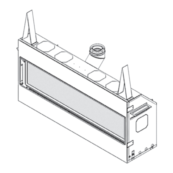
Page 21: Overview
QUALIFIED Overview INSTALLER Mantel—See Mantel & Hearth Clearances Framing—See Framing Requirements Remote Handset 1/2 inch thick non-combustible Wall Holder cement board – NOT supplied Supplied as vertical outlet, fi eld convertible to horizontal outlet. Note - Vertical rise required in S urrou u vent system Remote Battery... -
Page 22: Dimensions & Location
QUALIFIED Dimensions & Location INSTALLER Dimensions 72” (1829 mm) 66-1/4” (1683 mm) Center Line LDK Duct Kit outlets (remove plates) Top View Heat shield required for 18-5/8” rear vent (473 mm) outlet applications Zero Clearance 15-1/1 16” Stand-Offs (382 m 6-5/8”... -
Page 23: Mantel & Hearth Clearances
QUALIFIED Mantel & Hearth Clearances INSTALLER Combustible Mantel—Left Side View Ceiling Note: Use of the optional LDK Duct Kits affects mantel and hearth clearances. See instructions packed Mantel Projection with LDK Duct Kits. (from Face of Cement Board) 0 2” 4” 6” 8” 10” 12” 54”... - Page 24 QUALIFIED Mantel & Hearth Clearances INSTALLER Combustible Sidewall / Mantel Leg—Top View FIREPLACE Face of Finished Wall Fireplace Opening 64” (1626 mm) Wall Min. 4” (102 mm) to wall or combustible mantel leg...
-
Page 25: Framing Requirements
QUALIFIED Framing Requirements INSTALLER Framing Dimensions NOTE: Height of cavity may be Between underside affected by vent configuration - see page 26 of header and bottom of firebox 1/2” thick non-combustible cement board required above, on each side and below engine opening (NOT supplied) NOTE: This unit requires a 48”... - Page 26 QUALIFIED Framing Requirements INSTALLER Framing with Partial Shelf— Top Outlet 15-3/16” (386 mm) Approx. 10-3/4” (274 mm) from back surface of wall finish to front surface of appliance case w/no vent offset 1/2” thick Min. 1” non-combustible (25.4 mm) Cement Board clearance to combustibles around...
- Page 27 QUALIFIED Framing Requirements INSTALLER Venting Considerations—Vertical Takeoff Notes—ALL venting considerations • Dimensions of venting are based on using Dura-Vent elbows. Elbow curve 24” pipe section radius dimensions will vary when using other brands. In general, other brands have slightly bigger radius. •...
-
Page 28: Venting
QUALIFIED Venting INSTALLER Top or Rear Outlet Framing Vent in Combustible Walls & Ceilings This unit is supplied with a top vent outlet which can be fi eld-converted to a rear vent outlet. See Appliance When penetrating through combustible walls and Preparation section for more information. -
Page 29: Co-Axial Venting
QUALIFIED Co-axial Venting INSTALLER Typical Co-axial Venting Components HORIZONTAL TERMINATION 2-PIECE WALL THIMBLE PIPE 90˚ ELBOW LENGTH VERTICAL TERMINATION PIPE STORM LENGTH COLLAR FLASHING 90˚ ELBOW ATTIC INSULATION SHIELD HORIZONTAL TERMINATION ATTIC FIRESTOP CEILING FIRESTOP 2-PIECE Rear Outlet WALL THIMBLE PIPE PIPE LENGTH LENGTH... - Page 30 QUALIFIED Co-axial Venting INSTALLER How to Read the Venting Chart be used. Excludes the 45 degrees take-off elbow shipped with the appliance. The chart below applies to co-axial roof or wall 6. Each 90 degrees elbow installed on the horizontal termination.
- Page 31 QUALIFIED Co-axial Venting INSTALLER Restrictor The restrictor is located in the roof of the fi rebox hidden above the top liner panel. Adjust the restrictor before installation of the top liner panel. Should subsequent adjustment be required, you will need to remove the top liner panel—see page 41.
- Page 32 QUALIFIED Co-axial Venting INSTALLER Horizontal Vent Termination Location or a safety hazard. Local codes or regulations may require greater clearances. • The vent terminal must be located on an outside • The vent terminal must not be recessed into a wall wall or through the roof.
- Page 33 QUALIFIED Co-axial Venting INSTALLER Vertical Vent Termination Overhang should not extend beyond vent if within 48” of Horizontal termination cap Roof Minimum overhang Pitch "H" (feet) Flat to 7/12 Termination Min. 24” Over 7/12 to (unvented soffit) 1.5' 8/12 Min. 36” Vertical Min.
-
Page 34: Installation Planning
QUALIFIED Installation Planning INSTALLER Installer—READ THIS FIRST Only qualifi ed licensed or trained personnel 8. Install the venting system and tape vent pipe joints. should install this appliance. 9. Position the restrictor. 10. Connect the electrical wiring for optional electric 1. -
Page 35: Remove Heat Shield
QUALIFIED Installation INSTALLER Remove Heat Shield Fit optional LDK Duct Kit’s take-off collars to appliance (if used) Remove the heat shield from the top of the appliance case (3 screws). If using the top outlet, discard the See installation instructions packed with the LDK kits shield. -
Page 36: Plan Wall Finish
QUALIFIED Installation INSTALLER Plan Wall Finish Gypsum board Non-combustible cement board up to perimeter of cement board The L3 Linear fi replace requires a 1/2” (13 mm) thick non-combustible cement Min. 74-1/8” board to be used as a wall surface (1883 mm) immediately surrounding the unit on each 64-1/8”... -
Page 37: Remove Window
QUALIFIED Installation INSTALLER Cracking wall fi nishes • Always pre-drill screw holes through cement board and use screws with self-milling head. We recommend installing the optional LDK Duct Kit • Always use tape over joints. to reduce the wall temperatures and minimize the possibility of cracking wall fi... -
Page 38: Install Electrical Wiring (For Optional Accessories)
QUALIFIED Installation INSTALLER Install Electrical Wiring (for optional 2. Provide a steel surface mount electrical utility box (Iberville BC 1110 or equivalent), thread cable accessories) through knock-out in the end of box and through the This section provides information to install the electric cable clamp locking ring (if used). -
Page 39: Set-Up Gas Supply
QUALIFIED Installation INSTALLER 7. Pull the excess cable back through the cable clamp and tighten the locking ring to the cable clamp. Alternate clamp without locking ring may be used - ensure the proper clamp is used for the type of cable used. - Page 40 QUALIFIED Installation INSTALLER Pressure test the supply line for leaks. The appliance and its individual shut-off valve must be Window Flexible disconnected from the gas supply piping system during connector any pressure testing of that system at test pressures in supplied excess of 1/2 psig (3.5 kPa).
-
Page 41: Install Liners
QUALIFIED Installation INSTALLER Install Liners Place the panel’s right section on the ledge above the ports of the rear of the fi rebox. The section sits The liners install in the manner outlined below with the on the ledge behind the tabs, with its plain edge on exception of the 1825RGL Refl... - Page 42 QUALIFIED Installation INSTALLER 6. Place rear panel’s centre section on the ledge 10. Carefully lift, slide and position top panel on to left behind the tabs, slide it to the right so that its side and rear panel. stepped edge fi ts into the stepped edge of the rear panel’s right section.
-
Page 43: Install Driftwood Kit 1800Dwk
QUALIFIED Installation INSTALLER Install Driftwood Kit 1800DWK NOTE: Ensure the area within the pilot shield is clear of vermiculite. Material required • Driftwood Kit, which contains: ◊ Left and right steel platforms Pilot shield ◊ 7 logs ◊ 10 pebbles ◊... - Page 44 QUALIFIED Installation INSTALLER 3. Place the center rear log fi tting the log’s pegs into the holes of the platform as indicated. 4. Place the center front log fi tting the log’s pegs into the holes of the platform as indicated. 6.
- Page 45 QUALIFIED Installation INSTALLER 7. Place the right cross log into the front notch of the 8. Place the rocks on the platform as shown below. rear log; its peg serves here as a hook to maintain it Some of the rocks can be used to hide the platform in position.
-
Page 46: Install Decorative Glass Murano 1800Dgm
IMPORTANT: Approved for use only with the fi reglass to maximize the air gap behind the burner. provided with your Valor fi replace or the tempered crushed fi reglass brands American Fireglass™ or fi regear. The use of any other fi reglass products may void your fi... -
Page 47: Refi T Window
WARNING Failure to install the window correctly can leak carbon monoxide, affect the performance of the fi replace, damage components, cause overheating resulting in dangerous conditions. Damage caused by incorrect window installa- tion is not covered by the Valor warranty. -
Page 48: Install Remote Battery And Wall Switch Kit Rbwsk (Required)
QUALIFIED Installation INSTALLER Install Remote Battery and Wall Switch 4. Run harness assembly to mounted position of junction box, securing harness to framing using Kit RBWSK (required) insulated staples (not included) The Remote Battery and Wall Switch Kit is provided 5. - Page 49 QUALIFIED Installation INSTALLER 8. Mount switch plate to junction box with 2 long 12. Position battery holder to rear face and secure screws provided. Note: switch position left or right together with cable tie. note clearance is required to suit homeowner wishes. for battery snap connection.
-
Page 50: Initialize Remote Control
QUALIFIED Installation INSTALLER Initialize Remote Control Reset button The receiver and the handset of the remote control sys- Velcro tem must be initially synchronized before the fi rst use. Battery wall holder 1. Insert one 9 V alkaline battery in the handset. connection 2. -
Page 51: Install Trim And Barrier Screen
QUALIFIED Installation INSTALLER Install Trim and Barrier Screen Install the trim on the fi replace. Install as well the barrier screen which is provided with the trim. Show the customer how to remove the barrier screen to access the controls. Follow the instructions provided with the trim and leave those instructions behind for the customer’s further reference. -
Page 52: Wiring Diagram
QUALIFIED Wiring Diagram INSTALLER Remote Battery Holder Wall 4 AA Switch Batteries 5-pin connector 9-Volt connector GV60 Wiring Diagram... -
Page 53: Approved Venting Components
QUALIFIED Approved Venting Components INSTALLER Approved Direct Vent Suppliers - Valor Models 1800 Venting Parts Code / availability by Manufacturer Venting Parts Description Standard Co-axial 46DVA-HC 4DT-HC TM-4HT — — 4DHC round 658DVK2 940160 Deluxe Co-axial — — TM-4DHT —... - Page 54 QUALIFIED Approved Venting Components INSTALLER Venting Parts Code / availability by Manufacturer Venting Parts Description Galvanized 46DVA-06 4DT-06 TC-4DL6 SV4L6 94610606 6” long — — — Black 46DVA-06B 4DT-06(B) TC-4DL6B SV4LB6 90410606B Galvanized 7” long — — — — — —...
-
Page 55: Warranty
The warranty registration card must be completed by the initial owner and returned to the Company within 90 days of purchase. Alternatively, the warranty registration form may be fi lled out online at www.valorfi replaces.com. b) Installation and maintenance must be performed by an authorized and trained dealer in accordance with the Company’s installation instructions. -
Page 56: Spare Parts
OWNER’S Spare Parts INFORMATION Part Part Code Description Code Description Number Number Heat shield 4003049 Gaskets module plate, long (2) 3000400 45 degrees fl anged elbow 0945M Valve mount 4002905 Elbow gasket 4002999 GV60 valve assembly NG 4005082X Top stand-offs (2) 4002985 GV60 valve assembly LPG 4005083X... - Page 57 OWNER’S Spare Parts INFORMATION Part Code Description Number Black (2) 4005108 Murano Glass Fire 1800DGM LH Glass platform 4005366 RH Glass platform 4005367 Runners (4) 4005498AH Middle tabs (2) 4005499AH 1/2” Clear fi reglass bags (2) 4004521 Driftwook Kit 1800DWK LH Steel Platform 4004956AH RH Steel Platform...
- Page 58 OWNER’S Spare Parts INFORMATION 15a, 15b 20a, 27-33 40a, 40b...
- Page 59 Thank You ... For purchasing a Valor by Miles Industries. Your new radiant gas heater is a technical appliance that must be installed by a qualifi ed installer. Please fi ll in the information below. The information provided will be used for customer records only.
-
Page 60: Miles Industries Ltd
Tape Shut Fold here Postage needed Miles Industries Ltd. 190 - 2255 Dollarton Highway North Vancouver, BC V7H 3B1 Canada Online Warranty registration at www.valorfi replaces.com Thank you for choosing a Valor Product...
Need help?
Do you have a question about the 1800JN and is the answer not in the manual?
Questions and answers