Table of Contents
Advertisement
Quick Links
Installation and Operation Manual
Installation and Operation Manual
Installation and Operation Manual
CONTACT LOCAL BUILDING OR FIRE
CONTACT LOCAL BUILDING OR FIRE OFFICIALS ABOUT RESTRICTIONS AND
INSTALLATION INSPECTION REQUIREMENTS IN YOUR AREA.
INSTALLATION INSPECTION REQUIREMENTS IN YOUR AREA.
PLEASE READ THIS ENTIRE MANUAL BEFORE INSTALLATION AND USE OF THIS
PLEASE READ THIS ENTIRE MANUAL BEFORE INSTALLATION AND USE OF THIS
PLEASE READ THIS ENTIRE MANUAL BEFORE INSTALLATION AND USE OF THIS
PELLET
FUEL-BURNING
BURNING
BURNING
INSTRUCTIONS COULD RESULT IN PROPERTY DAMAGE, BODILY INJURY OR
INSTRUCTIONS COULD RESULT IN PROPERTY DAMAGE, BO
EVEN DEATH.
This manual is available for free download on the manufacturer's web site. It is a
This manual is available for free download on the manufacturer's web site. It is a
This manual is available for free download on the manufacturer's web site. It is a
copyrighted document. Re
copyrighted document. Re-sale is strictly prohibited. The manufacturer may update this
manual from time to time and cannot be responsible for
manual from time to time and cannot be responsible for problems, injuries, or damages
arising out of the use of information contained in any manual obtained from unauthorized
arising out of the use of information contained in any manual obtained from unauthorized
arising out of the use of information contained in any manual obtained from unauthorized
sources.
READ AND KEEP THIS MANUAL FOR REFERENCE
READ AND KEEP THIS MANUAL FOR REFERENCE
Printed in Canada
Eco-65
(DP00060 model)
PROFESSIONAL IS STRONGLY
OFFICIALS ABOUT RESTRICTIONS AND
ROOM
ROOM
ROOM
HEATER.
HEATER.
HEATER.
sale is strictly prohibited. The manufacturer may update this
Safety tested according to ULC S627,
y tested according to ULC S627,
UL1482 and ASTM E1509 by
UL1482 and ASTM E1509 by
an accredited laboratory
laboratory
INSTALLATION BY A
INSTALLATION BY A
IS STRONGLY
RECOMMENDED
RECOMMENDED
Fabricant de poêles international inc.
Fabricant de poêles international inc.
250, rue de Copenhague, St-Augustin
Desmaures (Québec) Canada G3A 2H3
Canada G3A 2H3
After-sale service: 418-908
E-mail: tech@sbi-international.com
international.com
www.drolet.ca
FAILURE
FAILURE
FAILURE
TO
TO
TO
problems, injuries, or damages
Augustin-de-
908-8002
FOLLOW
FOLLOW
FOLLOW
THESE
THESE
THESE
DILY INJURY OR
45725A
26-04-2016
Advertisement
Table of Contents

Subscribe to Our Youtube Channel
Related Manuals for Drolet Eco-65 DP00060


Summary of Contents for Drolet Eco-65 DP00060
- Page 1 Canada G3A 2H3 After-sale service: 418-908 908-8002 E-mail: tech@sbi-international.com international.com www.drolet.ca CONTACT LOCAL BUILDING OR FIRE CONTACT LOCAL BUILDING OR FIRE OFFICIALS ABOUT RESTRICTIONS AND OFFICIALS ABOUT RESTRICTIONS AND INSTALLATION INSPECTION REQUIREMENTS IN YOUR AREA. INSTALLATION INSPECTION REQUIREMENTS IN YOUR AREA.
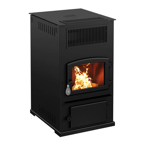
- Page 2 Eco-65 Installation and Operation Manual THANK YOU FOR CHOOSING THIS DROLET PELLET STOVE As one of North America’s largest and most respected pellet stove, wood stove and fireplace manufacturers, Stove Builder International takes pride in the quality and performance of all its products.
-
Page 3: Table Of Contents
Eco-65 Installation and Operation Manual Table of contents Introduction .............................. 5 1.1 About Pellet Heating ..........................5 1.1.1 Top 10 Reasons for Buying a Pellet Stove ................... 5 1.2 Appliance performance ........................6 1.3 General Features ..........................7 1.4 Overall Exterior Dimensions ........................8 PART A –... - Page 4 APPENDIX A: HORIZONTAL AND VERTICAL VENT CHART ..............86 APPENDIX B: INSTALLING A THERMOSTAT (AC05558) ................88 APPENDIX C: MOBILE HOME INSTALLATION .................... 91 APPENDIX D: COMBUSTION AIR SUPPLY ....................93 APPENDIX E: OPTIONAL HOT AIR PLENUM KIT (AC01330) ..............96 DROLET LIMITED LIFETIME WARRANTY ....................98...
-
Page 5: Introduction
Eco-65 Installation and Operation Manual 1 Introduction 1.1 About Pellet Heating Pellet stoves offer a dramatic improvement in the convenience of heating with solid fuel. Wood pellets are handled in bags and are therefore easily and cleanly stored. A single loading of a pellet stove can provide long hours of warmth. -
Page 6: Appliance Performance
Eco-65 Installation and Operation Manual 1.2 Appliance performance ☨ Fuel type Wood Pellet (Premium grade or better) Recommended heating area 800 to 2,600 ft (74 to 242 m Hopper capacity 125 lb (57 kg) Maximum burn time 104 h Maximum heat input rate 65,400 BTU/h (19.1 kW) Overall heat output rate (min. -
Page 7: General Features
Eco-65 Installation and Operation Manual 1.3 General Features 4 po (see Section 4.3: Equivalent Vent Length Recommended chimney diameter (EVL)) Flue outlet diameter 4 po (100 mm) Type of chimney ULC/ORD-C441, CAN/ULC S609, UL 641 (TYPE L) Baffle material Stainless Steel Approved for alcove installation Not approved Approved for mobile home... -
Page 8: Overall Exterior Dimensions
Eco-65 Installation and Operation Manual 1.4 Overall Exterior Dimensions FRESH AIR INLET EXHAUST... -
Page 9: Part A - Installation
Eco-65 Installation and Operation Manual PART A – INSTALLATION 2 Installation Safety Information 2.1 Installation Warnings, Cautions and Recommendations • PROFESSIONNAL INSTALLATION IS HIGHLY RECOMMENDED. • YOU MAY NEED TO OBTAIN A BUILDING PERMIT FOR THE INSTALLATION OF THIS STOVE AND ITS VENTING SYSTEM. -
Page 10: Regulations Covering Pellet Stove Installation
Eco-65 Installation and Operation Manual • MIXING APPLIANCE COMPONENTS FROM DIFFERENT SOURCES MODIFYING COMPONENTS IS PROHIBITED AND WILL VOID THE WARRANTY. • ANY MODIFICATION OF THE STOVE THAT HAS NOT BEEN APPROVED IN WRITING BY THE TESTING AUTHORITY IS PROHIBITED AND VIOLATES CSA B365 (CANADA), AND ANSI NFPA 211 (USA). -
Page 11: Clearances To Combustible Material
Eco-65 Installation and Operation Manual A POWER CORD OWNER’S MANUAL C TOP GRILL D SCRAPER DESICCANT (drying agent) SWEEPING BRUSH (the tie wrap must be cut) 3 Clearances to Combustible Material The clearances shown in this section have been determined by tests according to procedures set out in safety standards ULC S627 (Canada), ASTM E1509 (U.S.A). -
Page 12: Certification Label Location
Eco-65 Installation and Operation Manual 3.1 Certification Label Location Since the information given on the certification label affixed to the stove always overrides the information published in any other media (owner’s manual, catalogues, flyers, magazines and/or web sites), it is important to refer to it in order to have a safe and compliant installation. -
Page 13: Floor Protection
Eco-65 Installation and Operation Manual 3.3 Floor Protection For floor protection clearances refer to the following table. FLOOR PROTECTION LETTER CANADA 18″ (460 mm) 6″ (155 mm) N/A (USA only) 6″ (155 mm) N/A (Canada 8″ (205 mm) only) N/A (Canada 8″... -
Page 14: Venting System
Eco-65 Installation and Operation Manual 4 Venting system 4.1 General Even though the chimney draft is mechanical, a suitable venting system will ensure a natural draft which will prevent smoke spillage in your home if a power outage occurs. Moreover, a suitable venting system configuration will help getting the best efficiency out of your stove when installed in accordance with the required EVL (see Section 4.3: Equivalent Vent Length (EVL)). - Page 15 Eco-65 Installation and Operation Manual Here is an example to help you calculate Equivalent Vent Length. On the following figure the EVL can be calculated like this: • 2 horizontal run of 1’ = (2 X 1’) X 1’ = 2’ of EVL •...
-
Page 16: Termination Location
Eco-65 Installation and Operation Manual 4.4 Termination Location Termination should not be located so that hot exhaust gases can be a hazard. They can reach temperatures of 500°F (260°C) and cause serious burns. CAUTION: TERMINATION COLLAR (SPARK ARRESTER) IS MANDATORY. 4.4.1 Permitted Termination Location Refer to NFPA 211 (USA) or CSA B365 (Canada) for rules for the distance of exit terminal from windows and openings. -
Page 17: Installation Configurations
Eco-65 Installation and Operation Manual Canada: Min. Letter Description clearances Clearances above grade level or any adjacent surface that might 12’’ (30 cm) support snow, ice, or debris 39’’ (100 cm) Clearance to window or door that may be opened 39’’... -
Page 18: Through Wall Installation (Main Floor Or Basement)
Eco-65 Installation and Operation Manual • USE RTV SILICONE (Room Temperature Vulcanization), METALLIC TAPE, AND A MINIMUM OF THREE SELF-TAPING SCREWS AT ALL JOINT CONNECTIONS TO ENSURE A TIGHT SEAL. • THE CHIMNEY CONNECTOR SHALL NOT PASS THROUGH AN ATTIC OR ROOF SPACE, CLOSET OR SIMILAR CONCEALED SPACE OR FLOORS OR CEILING. -
Page 19: Through Roof Installation
Eco-65 Installation and Operation Manual 4.5.3 Through Roof Installation Position stove following clearances given Section 3.2: Minimum Clearances to Combustibles and following vent manufacturer’s instructions. 2. Install a cleanout tee to the stove exhaust. If necessary, use a horizontal additional length between the exhaust and the tee. -
Page 20: Through A Factory Built Chimney
Eco-65 Installation and Operation Manual 4.5.4 Through a Factory Built Chimney To make an installation through a factory built chimney, run a 4" stainless steel liner inside the factory built chimney. 1. Position stove following clearances given Section 3.2: Minimum Clearances Combustibles following... -
Page 21: Through An Existing Masonry Fireplace
Eco-65 Installation and Operation Manual 4.5.5 Through an Existing Masonry Fireplace 1. Position stove, following clearances shown Section 3.2: Minimum 12”-18” Clearances Combustibles following vent manufacturer’s instructions. 2. Build and Install a blocking plate inside the chimney to seal the fireplace damper. -
Page 22: Through An Existing Masonry Chimney
Eco-65 Installation and Operation Manual 4.5.6 Through an Existing Masonry Chimney 1. Position stove following clearances shown Section 3.2: Minimum 12”-18” Clearances Combustibles following vent manufacturer’s instructions. 2. Mark the center of the hole where the vent pipe will go through the masonry chimney. -
Page 23: Part B - Operation
Eco-65 Installation and Operation Manual PART B - OPERATION 4.6 General Information 4.7 Operation Warnings, Cautions and Recommendations • KEEP THIS MANUAL FOR REFERENCE. • DURING THE FIRST FEW FIRES, YOUR STOVE WILL EMIT AN ODOR AND A SMALL AMOUNT OF FUMES AS THE HIGH TEMPERATURE PAINT CURES OR BECOMES SEASONED TO THE METAL. - Page 24 Eco-65 Installation and Operation Manual • TURNING THE STOVE OFF DOES NOT DISCONNECT ALL POWER FROM THE STOVE. DISCONNECT THE POWER CORD BEFORE PERFORMING ANY MAINTENANCE OR REPAIRS ON THE STOVE. • ALLOW THE STOVE TO COOL BEFORE CARRYING OUT ANY MAINTENANCE OR CLEANING.
-
Page 25: Zone Heating And How To Make It Work For You
Eco-65 Installation and Operation Manual FIREBOX CLEARS AND BLOWERS SHUT DOWN. DO AS INSTRUCTED IN “EVERYDAY STARTUP” THEN ATTEMPT TO RESTART THE STOVE. IF THE PROBLEM PERSISTS, CONTACT YOUR DEALER. NOTE THAT SMOKE BUILD-UP DURING IGNITION MAY OCCUR. SMOKE CAN ACCUMULATE IN THE FIREBOX FOR A FEW SECONDS JUST BEFORE THE IGNITOR IS HOT ENOUGH TO FIRE-UP THE PELLETS IN THE BURN POT. -
Page 26: Combustible
Eco-65 Installation and Operation Manual 4.8 Combustible 4.8.1 Proper Fuel Each type of pellet has its properties and will burn differently. The amount of ashes produced can also vary greatly. Conventional pellets are those ¼” or 5/16” in diameter and not over 1” long. -
Page 27: Stove Controls
Eco-65 Installation and Operation Manual 5 Stove Controls 5.1 Control Panel The blowers and automatic fuel supply are controlled from a control panel (A) on the right- hand side of the ECO-65. The control panel functions are as follows:... -
Page 28: Mode Button
Eco-65 Installation and Operation Manual Control panel screen Operation mode : THERMOSTAT: Thermostatic control MANUAL (optional) Button to select Button to clear between modes most error codes Button to change the Button to feed and start convection fan speeds when the auger is empty Pellet burn rate Button + and –... -
Page 29: Fuel Feed Button
Eco-65 Installation and Operation Manual 5.1.2 Fuel Feed Button When the “Fuel Feed” button is pushed the stove will feed pellets continuously into the burn pot during 1 minute and then the ignition cycle will begin. The “Feed and Start” message will appear. -
Page 30: Adjustments
Eco-65 Installation and Operation Manual 5.2 Adjustments 5.2.1 Selecting the Combustion Level (Heat Rate) The heat input of the stove varies between 10,500 BTU/h to 65,000 BTU/h. To change the combustion level select the + or – button when the stove is in function. Note: Input range may vary according to the type of pellets being used. -
Page 31: Stove Operation
Eco-65 Installation and Operation Manual 6 Stove Operation 6.1 First Startup Before starting your stove, make sure that the burn pot, the baffle and the maintenance access panels are properly installed. Make sure that the stove has been emptied of all tools and accessories (see Section 2.3: Before Operating Your Stove). -
Page 32: Shutting Down Procedure
Eco-65 Installation and Operation Manual 6.5 Shutting Down Procedure To turn your stove off, press the button on the control panel until the LED light is in the OFF position. The cooling cycle will take a few minutes and the blowers will continue to function while the stove is cooling down. -
Page 33: Signs Of An Overheating Stove
Eco-65 Installation and Operation Manual 6.7 Signs of an Overheating Stove Under normal conditions, the flame should have a bright yellow color and be very active, but stable. If you see the flame getting lazy, very high and orange, it may be a sign that there is something wrong. -
Page 34: Maintenance
Eco-65 Installation and Operation Manual 7 Maintenance 7.1 Stove Maintenance 7.1.1 Recommended Maintenance Schedule Use this as a guide when used under average conditions. Weekly Twice a year Annually Components or after or after ± 250 pounds ± 1 tons ±... -
Page 35: Cleaning The Baffle, The Heat Exchanger And The Combustion Chamber
Eco-65 Installation and Operation Manual 7.1.2 Cleaning the Baffle, the Heat Exchanger and the Combustion Chamber Cleaning of the heat exchanger must be done on a regular basis (see Section 7.1.1: Recommended Maintenance Schedule). To access the heat exchanger you need to first rise up and pull towards you the decorative grill (A) above the viewing door. - Page 36 Eco-65 Installation and Operation Manual Using the provided sweeping rod, sweep up and down each exchanger. Make sure you go all the way down to the bottom. Reinstall the access panel to the combustion chamber and tighten the wing nuts. DO NOT USE PLIERS OR OTHER TOOLS TO TIGHTEN THE WING NUTS.
- Page 37 Eco-65 Installation and Operation Manual 1) Open the door and turn the lock (A) that can be found above the door opening. 2) Once the baffle (B) is unlocked, it will pivot downwards automatically. 3) Lift the baffle (B) from its pivots (C). Pull it down.
-
Page 38: Exhaust Channel And Exhaust Blower Maintenance
Eco-65 Installation and Operation Manual 4) Take out the baffle from the combustion chamber. IT IS HIGHLY RECOMMENDED TO CLEAN THE EXHAUST CHANNEL (SEE SECTION 7.1.3: EXHAUST CHANNEL AND EXHAUST BLOWER MAINTENANCE) IMMEDIATLY AFTER CLEANING THE HEAT EXCHANGER. 7.1.3 Exhaust Channel and Exhaust Blower Maintenance Exhaust channels and the exhaust blower are located on the left hand side of the stove. - Page 39 Eco-65 Installation and Operation Manual Using a Philips or Robertson screwdriver, remove both clean-out traps by unlocking them. Push the screw and give it a counter-clockwise quarter turn. Locate both openings. Using the provided scraper, remove the dirt in the bottom channel of the heat exchangers.
-
Page 40: Cleaning The Burn Pot
Eco-65 Installation and Operation Manual 7.1.4 Cleaning the Burn Pot The burn pot must remain clean and the holes should not be obstructed by combustion residues (ashes or clinkers). 1. Clean the burn pot using the scraper provided with the stove or a smaller one. - Page 41 Eco-65 Installation and Operation Manual 2. The burn pot simply sits onto the air intake channel. You must lift to remove it from the stove. Two small pins guide the burn pot in place. Make sure that the burn pot is well in place before turning on the stove (as shown in the diagram).
-
Page 42: Ash Removal
Eco-65 Installation and Operation Manual Verify that the clean out trap gasket is still in good condition, replace it if needed (3/16’’ black round gasket, AC06815). 7.1.5 Ash Removal 1. To empty the ash drawer (A) of its contents, open the ash pan access door by loosening the round knob on the bottom left hand side. -
Page 43: Cleaning The Air Wash System
Eco-65 Installation and Operation Manual 7.1.6 Cleaning the Air Wash System Vacuum the ashes that may have accumulated into the airwash system inlet between the bottom glass retainer and the glass. This will allow an optimum air flow along the inside portion of the glass and prevents the glass from sooting-up. -
Page 44: Door Gasket Maintenance
Eco-65 Installation and Operation Manual 7.1.9 Door Gasket Maintenance It is important to maintain the door gasket in good condition. After a while, the gasket will wear and compress; adjusting the door may then be required. If the door adjustment is not sufficient, replace the door gasket with a genuine part. -
Page 45: Venting System Maintenance
Eco-65 Installation and Operation Manual 7.2 Venting System Maintenance CAUTION: REGULARLY EXAMINE THE VENTING SYSTEM, THE JOINTS, AND THE SEALING TRIMS TO ENSURE THAT THE SMOKE AND THE COMBUSTION GASES ARE NOT DRAWN BY THE CONVECTION BLOWER. The most efficient method to sweep the venting system is by using a 4'' pellet brush depending on your installation. -
Page 46: Troubleshooting
Eco-65 Installation and Operation Manual 8 Troubleshooting When you have issues with your stove, your first reaction may be to call technical support. This section will help you save time and money by enabling you to solve simple problems by yourself. -
Page 47: Testing A Component
Eco-65 Installation and Operation Manual 8.2 Testing a Component If you suspect that an electrical component to be defective, you can test it by following the procedure given below. Note that you will be able to test only components when the stove is OFF and that all the components are no more in function. - Page 48 Eco-65 Installation and Operation Manual and Operation Manual Push the control key to proceed. control key to proceed. The frequency of the power source is displayed. The frequency of the power source is displayed. Push any control key to proceed. The tension of the power source is displayed The tension of the power source is displayed.
- Page 49 Eco-65 Installation and Operation Manual Displays the temperature read by the thermistor. Push any control key to proceed. Convection blower test. Push the control key to proceed. Combustion blower test. Push the control key to proceed. Exhaust blower test. Push the control key to proceed.
-
Page 50: Main Error Codes, Possible Causes And Solutions
Eco-65 Installation and Operation Manual 8.3 Main Error Codes, Possible Causes and Solutions WARNING: RISK OF ELECTRICAL SHOCK. IF YOU NEED TO MANUALLY TEST, MANIPULATE OR REPLACE ANY COMPONENTS, THE STOVE NEEDS TO BE DISCONNECTED FROM THE WALL OUTLET. This section contains main error codes, possible causes and many suggestions to guide you in resolving them. -
Page 51: P Code
Eco-65 Installation and Operation Manual 8.3.1 P Code STOVE SHUTS OFF AND APPEARS ON CONTROL BOARD Possible Remedies: (Unplug stove first when Possible Causes: possible) 1. Pressure tap (located on the Pull off the air hose from the exhaust blower pressure exhaust blower) is blocked. - Page 52 Eco-65 Installation and Operation Manual 8. Pressure switch is defective Even though this situation is highly unlikely, it’s (very rare). possible the pressure switch is defective. To test the airflow pressure switch, you need to disconnect the air hose from the blower casing. With the other end still attached to the switch, very gently suck on the loose end of the hose (you may want to completely disconnect the hose from the stove and the switch first...
-
Page 53: H Code
Eco-65 Installation and Operation Manual 8.3.2 H Code STOVE STOPS FEEDING PELLETS AND APPEARS ON THE CONTROL BOARD. BEFORE RESETTING TAKE CARE IN READING THE POSSIBLE CAUSES AND THEN PRESS ON AT THE SAME TIME FOR 2 SECONDS. Possible Cause: Possible Remedy: Remove the burn pot, make sure that all 1. - Page 54 Eco-65 Installation and Operation Manual NOTE: IF THE CODE APPEARS MORE THAN THREE TIMES, THE ERROR CODE WILL LOCK ITSELF UP. THIS PELLET STOVE IS EQUIPED WITH MULTIPLE DEVICES TO ENSURE YOUR SAFETY. IF A WARNING ERROR CODE STOPS YOUR STOVE ON SEVERAL OCCASIONS, IT IS MORE THAN LIKELY THAT THE STOVE DOES NOT EXHAUST PROPERLY.
-
Page 55: E Code
Eco-65 Installation and Operation Manual 8.3.3 E Code STOVE SHUTS OFF AND DISPLAYS WARNING CODE Possible Remedies: (Unplug stove first when Possible Causes: possible) 1. The stove ran out of pellets. Refill the hopper. Erase the error code and press the auger button (see Section 5.1.2: Fuel Feed Button). - Page 56 Eco-65 Installation and Operation Manual 5. The flue temperature sensor failed. The “thermistor” is a heat sensor located on the exhaust motor housing. Its function is to tell the control board that the stove has ignited properly by measuring the heat at the exhaust. The pellet stove will not start feeding pellets at the desired heat setting until it has received a signal from the thermistor heat sensor.
- Page 57 Eco-65 Installation and Operation Manual HOPPER AUGER Screws Auger and motor assembly gasket BURN POT AUGER Screws Auger and motor assembly GASKET...
-
Page 58: L Code
Eco-65 Installation and Operation Manual 8.3.4 L Code STOVE FEEDS PELLETS, BUT WILL NOT IGNITE AND APPEARS ON THE CONTROL BOARD Possible Causes: Possible Remedies: 1. Inadequate fuel is used. Remove the burn pot, make sure that all openings are clear and check that no ash has filled the tube around the igniter. -
Page 59: Code
Eco-65 Installation and Operation Manual 8.3.5 d Code STOVE STOPS FEEDING PELLETS AND APPEARS ON THE CONTROL BOARD Possible Cause: Possible Remedy: 1. The hopper lid has stayed open for more As a security measure, the auger stops than 3 minutes. turning and feeding pellets as soon as the hopper lid opens. -
Page 60: I Code
Eco-65 Installation and Operation Manual 8.3.8 I Code STOVE FEEDS PELLETS, BUT WILL NOT IGNITE AND APPEARS ON THE CONTROL BOARD Possible Cause: Possible Remedy: Test the resistance (ohms, Ω) with a multimeter. If the 1. The igniter fuse on the control board has blown. -
Page 61: Smoke Smell
Eco-65 Installation and Operation Manual 8.3.10 Smoke Smell SMOKE SMELL COMING BACK INTO THE HOME Possible Causes: Possible Remedies: 1. Venting system leaks. Inspect all vent connections. This is a pressurized venting system. All vent connector joints must be sealed and fastened in accordance with the pellet vent manufacturer's instructions to ensure consistent performance and avoid smoke and ash spillage (see Section 4.5.1: Installation... -
Page 62: Auger Motor Stops Momentarily
Eco-65 Installation and Operation Manual 8.3.11 Auger Motor Stops Momentarily AUGER MOTOR STOP FEEDING PELLETS AND COMES BACK ON Possible Cause: Possible Remedy: 1. The auger motor is overheating and It’s possible that the auger is jammed. tripping the internal temperature shutoff Remove it from its housing (see drawing (thermal protector). -
Page 63: No Display
Eco-65 Installation and Operation Manual 4. Air intake channel is Visually inspect the air intake channel that leads to the burn pot for restricted. foreign material. Make sure that the air-intake shutter is functional and free of any obstruction. 5. The See Section 8.2: Testing a Component and test the combustion combustion/exhaust and the exhaust blowers independently. -
Page 64: Wiring Diagram
Eco-65 Installation and Operation Manual 9 Wiring Diagram... -
Page 65: Access To Fuses
Eco-65 Installation and Operation Manual 10 Access to Fuses WARNING: UNPLUG THE STOVE BEFORE CHANGING THE FUSES. All fuses are located inside the housing of the electronic board; the housing is on the back of your stove. Unplug your stove, remove the screw and turn the four spring clips to open the housing. - Page 66 Eco-65 Installation and Operation Manual LETTER FUSE FUNCTION AMPERAGE MAIN BOARD FUSE 7.5A CONVECTION BLOWER COMBUSTION BLOWER EXHAUST BLOWER TOP AUGER #1 BOTTOM AUGER #2 IGNITOR...
-
Page 67: Components Location
Eco-65 Installation and Operation Manual 11 Components Location LETTER COMPONENT HEAT EXCHANGER TUBES BURN POT IGNITOR CONVECTION BLOWER THERMISTOR L-250 THERMAL SWITCH HOPPER CONTROL PANEL HOPPER SAFETY SWITCH PRESSURE SWITCH F-160 THERMAL SWITCH POWER CORD RECEPTACLE THERMOSTAT TERMINAL BLOCK COMBUSTION BLOWER/FRESH AIR INTAKE EXHAUST BLOWER BOTTOM AUGER #2... -
Page 68: Blower Replacement
Eco-65 Installation and Operation Manual 12 Blower Replacement CONVECTION BLOWER Unscrew screw A (1), slightly pivot the fan upward then partially slide the fan out (2). Disconnect the fan from the harness and remove completely. - Page 69 Eco-65 Installation and Operation Manual COMBUSTION BLOWER Remove the 9 screws (A) and the bottom grille (B). Unlatch the clamps (C). Remove the back draft shutter (G) and the gasket (D). Pull the combustion blower (F) and unplug the wire connector from the harness. Remove the plug (E) of the blower.
- Page 70 Eco-65 Installation and Operation Manual EXHAUST BLOWER Remove the left panel. Unplug the connections (A) and (B). Unplug the silicone tube (C).
- Page 71 Eco-65 Installation and Operation Manual Remove the clamp (D). With a Philips screwdriver, unlock and remove the access panel (E).
- Page 72 Eco-65 Installation and Operation Manual Remove the nuts (F) located in the opening of the trapdoor. Remove the duct assembly (G).
- Page 73 Eco-65 Installation and Operation Manual Remove the bolts (H) and nuts (I) to remove the exhaust blower (J)
-
Page 74: 250 And F-160 Thermal Switch Replacement
Eco-65 Installation and Operation Manual 13 L-250 and F-160 Thermal Switch Replacement L-250 1. Remove both retaining screws (A) holding the thermal switch support bracket (B). 2. Lift up the support bracket. Rotate the bracket 90° clockwise then pull the bracket toward you. - Page 75 Eco-65 Installation and Operation Manual Remove the faulty thermal switch. Replace new thermal switch (D) underneath the bracket (B) by means of 2 screws (C). F-160 Unscrew both screws (B) and take out the thermal switch F-160 (A).
-
Page 76: Exploded View And Replacement Parts
Eco-65 Installation and Operation Manual 14 Exploded View and Replacement Parts SECTION A... - Page 77 Eco-65 Installation and Operation Manual SECTION B...
- Page 78 Eco-65 Installation and Operation Manual SECTION C...
- Page 79 Eco-65 Installation and Operation Manual SECTION D SECTION E...
- Page 80 Eco-65 Installation and Operation Manual SECTION F SECTION G...
- Page 81 Eco-65 Installation and Operation Manual SECTION H SECTION I...
- Page 82 Eco-65 Installation and Operation Manual SECTION J SECTION K...
- Page 83 Eco-65 Installation and Operation Manual IMPORTANT: THIS IS DATED INFORMATION. When requesting service or replacement parts for your stove, please provide the model number and the serial number. We reserve the right to change parts due to technology upgrade or availability. Contact an authorized dealer to obtain any of these parts.
- Page 84 Eco-65 Installation and Operation Manual Item Description PL67173 BAFFLE EXTENSION 30799 STEEL ROUND KNOB, 3/8"-16 THREADED 30800 FULLY THREADED STEEL EYE BOLT, 3/8"-16 SE67151 ASH DRAWER ACCESS DOOR AC06825 GASKET KIT SELF ROUND BLACK 3/4" 30055 HINGE PIN RETAINING RING 5/16" ID X 0.512" OD 30167 HINGE PIN 5/16 DIA.
- Page 85 Eco-65 Installation and Operation Manual Item Description 44015 FUSE 5A / 250V / 1/4" DIA. X 1 1/4'' L 44016 FUSE 3A / 250V / 1/4" DIA. X 1 1/4'' L 30132 SCREW #10 X 3/8" HEX WASHER ZINC GR 5 TYPE "A" 30408 ELECTRONIC BOARD CLIP PL64459...
-
Page 86: Appendix A: Horizontal And Vertical Vent Chart
Eco-65 Installation and Operation Manual APPENDIX A: HORIZONTAL AND VERTICAL VENT CHART Possible Horizontal vent length (feet) For example, let’s imagine an installation consisting of a horizontal vent coming out at the back of the stove on a total distance of 8 feet. This horizontal run is followed by a tee and a 6-foot vertical rise. - Page 87 Eco-65 Installation and Operation Manual Instead, if the installation consisted of a horizontal vent coming out at the back of the stove on a total distance of 4 feet, followed by a tee and a 6-foot vertical rise, it would be acceptable.
-
Page 88: Appendix B: Installing A Thermostat (Ac05558)
Eco-65 Installation and Operation Manual APPENDIX B: INSTALLING A THERMOSTAT (AC05558) Using a thermostat will help you maintain a constant temperature throughout the house. A low voltage thermostat (24 volts) is required. A fixed wall mount or hand held model can be used. - Page 89 Eco-65 Installation and Operation Manual Wired thermostat Before installing the thermostat, unplug the power cord from the power outlet. First, connect the two thermostat wires to the terminal block located at the rear on the right hand side of the stove when facing it. Loosen the two middle screws and insert the wires in the terminals.
- Page 90 Eco-65 Installation and Operation Manual Wireless thermostat If you are using a wireless thermostat or a hand held thermostatic remote control, connect the two thermostat wires to the terminal block located at the rear on the right hand side of the stove while facing it.
-
Page 91: Appendix C: Mobile Home Installation
Eco-65 Installation and Operation Manual APPENDIX C: MOBILE HOME INSTALLATION Anchor the stove WARNING: FOR MOBILE HOME INSTALLATION, IT IS MANDATORY TO CONNECT THE STOVE TO AN OUTSIDE COMBUSTION AIR SOURCE. (SEE APPENDIX D: COMBUSTION AIR SUPPLY). When installed in a mobile home, the stove must be anchored to the floor with two screws. Use the two anchoring holes (A) located for this purpose on each side of the pedestal, as shown on the following image. - Page 92 Eco-65 Installation and Operation Manual Fresh air intake Pellet pipe length and/or slip section Ceiling support Attic insulation shield Roof flashing Storm collar Pellet pipe length Vertical rain cap...
-
Page 93: Appendix D: Combustion Air Supply
Eco-65 Installation and Operation Manual APPENDIX D: COMBUSTION AIR SUPPLY WARNING: FOR MOBILE HOME INSTALLATION, IT IS MANDATORY TO CONNECT THE STOVE TO AN OUTSIDE COMBUSTION AIR SOURCE. INSULATED PIPE SHOULD NEVER EXCEED 10 FEET. It is recommended to install an outside air inlet in or near the room where the stove is installed. - Page 94 Eco-65 Installation and Operation Manual To complete the installation, make a hole of1/4" to 1/2" (6 mm à 13 mm) bigger than the insulate pipe diameter in the outside wall of the house at the chosen location. From outside, place the outside air inlet cap (E) in the hole (open side down) and fasten the register to the wall, with screw.
- Page 95 Eco-65 Installation and Operation Manual Sources of Outside Combustion Air WARNING: IT IS FORBIDDEN TO DRAW COMBUSTION AIR FROM A BASEMENT, AN ATTIC, A GARAGE OR ANY CONFINED SPACE. • You can draw air from a ventilated crawl space underneath the floor. •...
-
Page 96: Appendix E: Optional Hot Air Plenum Kit (Ac01330)
Eco-65 Installation and Operation Manual APPENDIX E: OPTIONAL HOT AIR PLENUM KIT (AC01330) The hot air plenum kit AC01330 is available at your local dealer. Please note that the 3.25” x 10” duct is sold separately. Duct 3.25” x 10”... - Page 97 Eco-65 Installation and Operation Manual This hot air plenum kit contains the following parts: (A) -49068 (B) -PL62444 (C) -SE62443 (D) -PL62446 (5” x 17.5”) (E) -30153 (F) -30220 (G) PL67179 (DP00060) (3” x 16”)
-
Page 98: Drolet Limited Lifetime Warranty
Labour cost and repair work to the account of the manufacturer are based on a predetermined rate schedule and must not exceed the wholesale price of the replacement part. Shall your unit or a components be defective, contact immediately your DROLET dealer. To accelerate processing of your warranty claim, make sure to have on hand the following information when calling: •...
Need help?
Do you have a question about the Eco-65 DP00060 and is the answer not in the manual?
Questions and answers