Table of Contents
Advertisement
Quick Links
Advertisement
Table of Contents

Related Manuals for Otto Bock B400b400


Summary of Contents for Otto Bock B400b400
- Page 1 B400 Instructions for Use (User)
-
Page 3: Table Of Contents
Table of contents Table of contents Foreword ............... 5.3.2 Adjusting the back angle ........5.3.3 Adjusting the side panels ........Product Description ..........5.3.4 Adjusting the footrests ........Function ............5.3.5 Adjusting the belt lengths ......... Product Overview ..........5.3.6 Adjusting the control panel ....... - Page 4 Table of contents Batteries/charging process ....... 6.12 Additional options ..........6.7.1 Safety Instructions ........... 6.12.1 Control panel holder ........6.7.2 General ............6.12.2 Lights ............6.7.3 Battery charging information ......6.12.3 Belts / belt systems .......... 6.7.4 Battery charger ..........6.12.4 Suspension ............
- Page 5 Table of contents Maintenance ........... 7.2.1 Maintenance intervals ........Repair ............7.3.1 Replacing a defective fuse ........ 7.3.2 Replacing a defective bulb ........ 7.3.3 Replacing the battery ........Troubleshooting ..........7.4.1 Types of notifications ........7.4.2 Wheelchair control unit fault overview ....
- Page 6 Foreword Please note the following: 1 Foreword • If you have any questions or cannot solve a problem despite reading these instructions for use, please con INFORMATION tact the qualified personnel who fitted the product or the Date of the last update: 2013-08-15 manufacturer's service department (please see inside ►...
-
Page 7: Product Overview
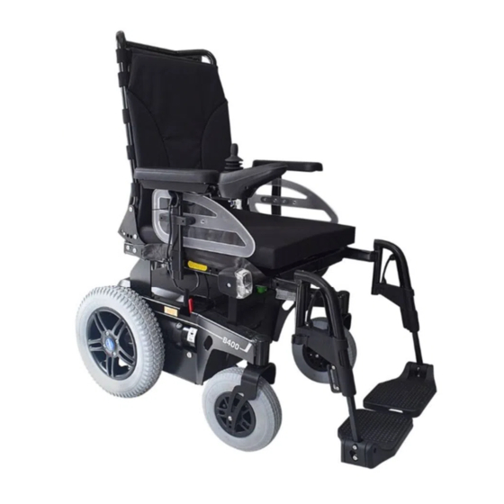
Product Description 2.2 Product Overview • The operational safety of the wheelchair can only be ensured if it is used properly in accordance with the information contained in these instructions for use. The user is ultimately responsible for accident-free opera tion. -
Page 8: General Safety Instructions 8
Safety 3 Safety ► You must observe road traffic regulations when driving in road traffic. 3.1 Explanation of Warning Symbols WARNING Warnings regarding possible risks of severe WARNING Failure to heed or observe the safety instructions accident or injury. Risk of pinching, crushing, being pulled in, tipping, falling Warnings regarding possible risks of acci... - Page 9 Safety • Chapter "Usage" > "Manual Seat Functions" CAUTION • Chapter "Usage" > "Disassembly/Transport" Extreme temperatures • Chapter "Usage" > "Use in a Wheelchair Accessible Risk of hypothermia or burns on components, failure of Vehicle" components • Chapter "Usage" > "Care" ►...
- Page 10 Safety 3.4 Name plate and warning labels 3.4.1 Name plate Label Meaning Type designation Read the instructions for use before using the product. Observe safety information in the instructions for use. Symbol for separate collection of electric and electronic devices. Com ponents of the power wheelchair and batteries may not be disposed of in household waste.
- Page 11 Safety Label Meaning Manual driving mode: unlock motor brake Risk of pinching. Do not reach into the danger area. (Only for installation of ISO sets according to ISO 7176) Fixation point/eyebolt for fastening the product in wheelchair access ible vehicles B400 Ottobock | 11...
- Page 12 Delivery 4.3.2 In case of extended disuse 4 Delivery NOTICE 4.1 Scope of supply Deep discharge due to standby current The power wheelchair is normally shipped fully assembled Risk of battery damage and fitted to the personal requirements of the respective user.
-
Page 13: Preparation For Use
Preparation for Use Note regarding the tyres 5 Preparation for Use • If the power wheelchair is not moved for several days, 5.1 Safety Instructions permanent colour changes may occur where the wheel chair comes into contact with the surface it is standing WARNING on. -
Page 14: Adjusting The Back Angle
Preparation for Use Seat height, seat width and seat angle are set according to CAUTION the customer order and may only be changed by a specialist Unsecured screw connections dealer. Risk of pinching, crushing, tipping over, falling of user The following can be adjusted by the user: ►... -
Page 15: Adjusting The Side Panels
Preparation for Use Fig. 2 Adjusting the back angle Fig. 3 Thumb screw for adjusting the height Adjusting the armrest to the forearm length 5.3.3 Adjusting the side panels 1) Loosen the two Allen head screws (Allen key, size 3) on INFORMATION the bottom of the armrest (see Fig. 4, item 1). -
Page 16: Adjusting The Footrests
Preparation for Use 2) Adjust the footplate bar to match the user's lower leg length. INFORMATION: Ensure that the footplate bar is inserted into the swivel segment by at least 40 mm. 3) Re-tighten the footrest bar screws. Fig. 4 Adjusting the armrest depth 5.3.4 Adjusting the footrests INFORMATION To remove and install the footrests: see Page 18. -
Page 17: Changing Control Unit Parameters
Preparation for Use Adjusting the control panel to the forearm length INFORMATION 1) Loosen the 3 set screws on the bottom of the armrest. The control panel mounting side may only be changed by 2) Slide the rail with the control panel forwards or back authorised personnel. -
Page 18: Usage
Usage 6 Usage 6.1 Side panels INFORMATION For additional information on side panels with lighting: see Page 48. Removing the side panel 1) Loosen the wing screw on the side panel holder (see Fig. 7, arrow). 2) Pull the side panel out from the side panel holder and set it aside. -
Page 19: Getting In / Transfer
Usage Installing the footrests INFORMATION Proceed as follows if a footrest must be installed: For detaching/attaching the power footrest: see Page 40. 1) Hook the footrest into the holder from above. 2) Swing the footrest forward until the footrest lock Removing the footrests engages (see Fig. 8, item 2). - Page 20 Usage Getting in from the front CAUTION Exposed pinch points Pinching, crushing of fingers ► Ensure that your fingers are not in the danger area when flipping the footrests up or down. 1) Place the seat in the horizontal position. 2) Fold up the footplates (see Fig. 9).
-
Page 21: Control Unit
Usage Getting in from the side Since the control unit is programmable, it can be adapted to the personal requirements of the user; e. g. the speed, 1) Place the seat in the horizontal position. acceleration and deceleration values can all be adapted. 2) Bring the power wheelchair as close as possible to where the user is sitting. - Page 22 Usage Fig. 11 VR2 control panel, version 1 Fig. 12 VR2 control panel, version 2 1 Joystick 5 [Horn] button 1 Joystick 6 Selected speed level (LED display) 2 [Decrease Speed] button 6 [On/Off] button 2 [Direction Indicator 7 [Warning Flasher On/Off] 3 [Increase Speed] button 7 Battery capacity (LED indic...
-
Page 23: Buttons And Display Functions
Usage 6.4.2 Buttons and display functions tions. To access "Seat function 3", it is necessary to use a toggle under the armrest (control panel side) (see Joystick Page 41). The speed and driving direction are controlled with the joy stick. If a power seat function is activated, the joystick is [Horn] button used to operate the seat function. -
Page 24: Driving Functions
Usage Battery indicator on the control panel accordingly. Moreover at low temperatures the battery capacity displayed on the control panel can differ more sig Display Information nificantly from the actual battery capacity. Battery is charged The "Battery Capacity" LED display (see Fig. 11, item 7; see Fig. 12, item 11) is divided into 10 segments and indic... - Page 25 Usage ► Practise using the product on level, open ground first. CAUTION Risk of uncontrolled driving behaviour Hazards while driving Risk of falling, tipping, collision with persons or nearby objects WARNING ► If any faults, defects or other hazards that can lead to Uncontrolled rolling personal injury are detected, the product must be Risk of collision with persons nearby objects...
- Page 26 Usage Hazards due to defective tyres ► Turn all mobile devices off while driving, since the driv ing characteristics of the product are affected by elec CAUTION tromagnetic fields. Defective tyres ► Turn the control unit off when it is not required, since Accidents/falling due to poor traction, reduced braking the product may generate electromagnetic fields that force or lack of manoeuvrability...
-
Page 27: Driving Notes
Usage Further Information Obstacles (steps, curbs): The critical obstacle height is 60 mm (with curb climb • INFORMATION ing assist, 100 mm). Obstacles higher than 60 mm must During use of the power wheelchair, electrical discharges crossed. (high voltage with low current; discharge via the user) may INFORMATION: This information applies to the occur which are caused by factors such as friction. -
Page 28: Switching On And Off
Usage Driving on rough terrain: WARNING The speed must be reduced in dangerous areas (e.g., Defective safety functions select speed level 1). Risk of falling, tipping, collision with persons or nearby • Typical dangerous areas include: objects – Narrow paths along waterways/slopes/cliffs (e.g., ►... -
Page 29: Selecting The Speed Levels
Usage 6.5.4 Selecting the speed levels ► Only drive on inclines and over obstacles with the seat • The power wheelchair has 5 speed levels. lowered and with a vertical backrest. The seat can be tilted back slightly when driving downhill. •... -
Page 30: Range
Usage 6.5.7 Drive-away lock • The maximum speed at full deflection of the joystick depends on the selected speed level. The power wheelchair control unit features an electronic drive-away lock. This function is activated/deactivated via • Releasing the joystick automatically activates the brake the control panel. -
Page 31: Adjusting The Driving Characteristics
Usage 2) Push the joystick all the way back until a beep sounds. ► Note that modified parameter settings in the configura tion can lead to changes in driving characteristics. In 3) Release the joystick. particular, changes to the speed, acceleration, braking →... - Page 32 Usage ► Lock the brake every time before parking the power Display Information wheelchair. Brake is released WARNING Flashing light Improper maintenance, repair, or adjustment work on the brake Falling, tipping, collision with persons or nearby objects ► Repairs and adjustments to the brake may only be made by qualified personnel trained by the manufac...
-
Page 33: Batteries/Charging Process
Usage 6.7.2 General The standard version of the power wheelchair is equipped with 2 maintenance-free AGM batteries with a capacity of 50 Ah (C5). Optionally, the power wheelchair can be equipped with maintenance-free batteries with capacity 63 Ah (C5). The batteries are located under the seat of the power wheel chair, below the battery cover. -
Page 34: Battery Charger
Usage 6.7.4 Battery charger • The batteries can be charged at any time, regardless of the remaining battery capacity. NOTICE It takes about 10 hours until a discharged battery (only • Improper use of the battery charger 1 flashing segment) is completely charged. When the Damage to the battery charger, damage to the battery due charging process is complete, the battery charger can to user error... -
Page 35: Charging The Battery
Usage Please see the instructions for use supplied with the battery NOTICE charger for further details on use and on the LED displays. Improper charging 6.7.5 Charging the battery Damage to the batteries due to user error ► Avoid deep discharge of the battery. The manufacturer WARNING does not assume any liability for damage due to deep Discharge of explosive gases during battery charging... -
Page 36: Power Seat Functions
Usage 7) Turn the power wheelchair control unit on. ► Drive in street traffic only with the seat tilt and seat height adjustments lowered and with a vertical back → The power wheelchair is ready to use. rest. ► Drive with the seat raised or with the seat tilt/back angle adjustment activated only for short distances at home. -
Page 37: Power Seat Height Adjustment
Usage ► When using power seat options, note that the seat WARNING function actuators are not designed for continuous Exposed pinch points in the seat adjustment and lift use, only for short-term use under limited loads (10% ing areas load, 90% idle time). Risk of pinching, crushing of limbs ►... - Page 38 Usage ► Ensure that creep speed is activated when the seat ► Observe the instructions for use in the sections "Elec height adjustment function is used. If this is not the tric Seat Functions" > and "Joystick Functions". case, contact a specialist dealer immediately. Only use The power wheelchair can be equipped with a power seat the power wheelchair with the seat height adjustment height adjustment feature.
-
Page 39: Power Seat Tilt
Usage Display Information The power seat tilt function allows the seat to be tilted, for example to relieve pressure. The power seat tilt is available Creep speed in 2 different versions: Power seat tilt up to 20° • Power seat tilt up to 45° Flashing •... -
Page 40: Power Footrests
Usage ► When driving with the back angle adjustment activ ated, fasten the belts (lap belt, four-point belt) and do not lean out beyond the seat surface. INFORMATION ► Please also observe the safety instructions in the sec tion "Electric Seat Functions" > "Safety Instructions for Use". -
Page 41: Controlling Power Seat Functions
Usage Fig. 19 Power footrest flipped up Fig. 20 Removing the footrest The footplates can be flipped up to increase the entry and 6.8.6 Controlling power seat functions exit area. • If the power wheelchair is equipped with one or more In addition, the electrically adjustable footrests can be power seat functions, they are activated and controlled removed from their brackets and lifted up (see Fig. 20, item... -
Page 42: Joystick Functions
Usage Activating "Seat function 2" ("Seat function 1" must • already be activated): move the joystick sideways to the right to activate "Seat function 2" (see Fig. 12, item 1). The LED display on the right lights up when the func tion is activated (see Fig. 12, item 3b). -
Page 43: Manual Seat Functions
Usage 6.9.2 Manual seat tilt Seat Function Joystick movement Footrests Forward: Both footrests move up WARNING Back: Both footrests move down Unintentional lowering of the seat tilt Direction of movement can be modified by the specialist Risk of pinching, crushing of limbs dealer. -
Page 44: Manual Back Angle Adjustment
Usage Adjusting the Back Angle 1) Activate the release lever on the armrest (see Fig. 23). 2) Move the backrest to the desired position. 3) Let go of the release lever. → The backrest is adjusted. Fig. 22 Tilting the seat manually 6.9.3 Manual back angle adjustment INFORMATION ►... -
Page 45: Additional Seat Options
Usage 6.10.1 Contour seat The mechanical elevating footrests with a gas compression spring make it possible to prevent constant pressure or to Compared to the standard seat, the contour seat provides provide anti-shock support. the user with improved comfort and lateral support. Swivelling the footrest 1) Activate the release lever on the footrest (see Fig. 24). -
Page 46: Attendant Control
Usage Functional overview The attendant uses the attendant control to operate the driv ing function and the power seat functions. The module is connected in conjunction with the control panel or as a separate input device. Fig. 26 Headrest with mounting kit 6.11 Control unit accessories The power wheelchair can be equipped with the following optional control unit accessories. - Page 47 Usage Joystick Seat function 1/2 (LED display) The attendant uses the joystick to control the speed and This LED display shows the currently active power add-on driving direction. When a seat option is activated, the joy function. stick operates this seat option. [Select Speed Level] Button [Activate/Deactivate Attendant Control] Button Pressing the button increases/decreases the speed level.
-
Page 48: Additional Options
Usage 2) Swing the control panel holder away to the side. INFORMATION: The pivot element locks in place again when the holder is rotated back to the origin al position. Fig. 28 External odometer 6.12 Additional options 6.12.1 Control panel holder Fig. -
Page 49: Belts / Belt Systems
Usage The front lights are fastened to the self-contacting side pan els. When the side panels are inserted into the side panel holders the contacts touch each other and current can flow (see Fig. 31, right). To replace broken lights: see Page 63. Fig. - Page 50 Usage Opening the lap belt ► Ensure that the lap belt is not too tight against the body. ► Press the red release button. ► Remove objects or clothing which get caught. → The buckle is open and the belt can be removed. Adjusting the belt length The lap belt provides additional support and keeps the user from sliding out of the seat.
- Page 51 Usage CAUTION Putting the four point belt on incorrectly Risk of pressure points, constriction ► Ensure that the bottom belt is not too tight between the lap belt and the thigh. ► Ensure that the buckle lies in the middle of the body. ►...
-
Page 52: Suspension
Usage 6.12.5 Locking the steering casters 3) Turn the buckle back to the original position when the belt length is correct. The power wheelchair may be equipped with a steering caster lock. 4) To shorten: Pull on the free belt end. It locks the steering casters in the forward direction so turn... -
Page 53: Luggage Carrier
Usage Fig. 36 Luggage carrier, back Fig. 35 Steering caster lock, engaged and disengaged 6.12.7 Overview of additional options 6.12.6 Luggage carrier INFORMATION NOTICE Overloading the luggage carrier You can find these and other optional add-on components on the order form and in the wheelchair accessories cata Damage to product due to breakage logue. -
Page 54: Disassembly/Transport
Usage • Puncture-proof tyres: Solid rubber tyres WARNING • Seating shell adapter: To attach special seating shells; Improper transportation in aircraft control panel holder for seating shells also available Burns, explosion or damage to the battery due to failure to •... -
Page 55: Reducing The Transportation Size
Usage ► During transport in another vehicle, the power wheel chair must be secured sufficiently with cargo straps. Only attach the cargo straps to the corresponding transportation eyelets and specified tie-down points. NOTICE Improper transport Risk of damage to the power wheelchair ►... -
Page 56: Preparing For Transport
Usage Fig. 38 Removing the cross bolt Fig. 39 Eyebolts 1 Cross bolt 2 Lever 1 Eyebolts, front 2 Eyebolts, back 6.13.3 Preparing for transport 6.14 Use in a wheelchair accessible vehicle 1) Lift and position the power wheelchair in its transport 6.14.1 Safety Instructions location. -
Page 57: Permitted Use
Usage 6.14.3 Restrictions for Use ► Never transport more than one person in the power wheelchair. WARNING ► Use the power wheelchair in a wheelchair accessible Unallowable use as a seat in a wheelchair accessible vehicle only if the seat is all the way down and the vehicle backrest is in a vertical position. -
Page 58: Use
Usage The weight of the person being transported is limited to max. 100 kg in a wheelchair accessible vehicle. 6.14.5 Use Ensure that the wheelchair is fully secured with tensioning straps during transportation in a wheelchair accessible vehicle. For more information please refer to our brochure on using Ottobock products in wheelchair accessible vehicles, order number 646D158. -
Page 59: Cleaning
Maintenance/Repair ► To avoid corrosion, don't use any aggressive cleaning 7 Maintenance/Repair agents or solvents. 7.1 Safety Instructions ► Check the driving behaviour of the product after clean ing it. WARNING Improper maintenance, repairs or adjustments INFORMATION User injuries, damage to the product due to failure to Piston rods do not require lubrication. -
Page 60: Maintenance
Maintenance/Repair ► Inspect the seat adjustment features for visible signs of damage at least 1 x per month and ensure all screw connections are tight. ► Maintain sufficient air pressure in the tyres. The correct tyre pressure is printed on the tyre casing and listed in the section "Technical Data". -
Page 61: Maintenance Intervals
Maintenance/Repair 7.2.1 Maintenance intervals The functions described below must be checked by the user or an attendant at the specified intervals: Component Activity Prior to Weekly Monthly every use Rear wheels Check whether wheel mounts are securely fastened Check whether the central nut on the drive shaft is securely fastened Check whether wheels rotate freely and without axial runout Check directional stability of the power wheelchair... - Page 62 Maintenance/Repair Component Activity Prior to Weekly Monthly every use Tyres Check for damage Batteries Check battery charge condition Lights Check for external damage Verify functionality Electronics Check the proper functioning of the control unit (inform qual ified personnel of any LED error messages) Check the proper functioning of the battery charger (inform qualified personnel of any LED error messages) Check plug connections...
-
Page 63: Repair
Maintenance/Repair 7.3 Repair 7.3.1 Replacing a defective fuse INFORMATION When replacing, only use fuses of the same type. Note the rating printed on it.Note the rating printed on it. The fuse (for values see section "Technical Data" > Table "Electrical System") is located in a fuse holder underneath the seat, next to the controller. - Page 64 Maintenance/Repair 3) Turn the defective bulb slightly to unlock it and then INFORMATION remove it. Lamp housings and lamps can both be ordered from the 4) Grasp the new bulb with a cloth, insert it into the socket specialist dealer. and lock it in place.
-
Page 65: Replacing The Battery
Maintenance/Repair Replacing the rear LED light (including rear direction ► If the driving function is still not available after turning indicator) the control unit on again, activate pushing mode by The rear LED light (see Fig. 30) is maintenance-free. If releasing the brake. repairs are required, the qualified personnel who fitted the ►... - Page 66 Maintenance/Repair user attempts to activate the motor. However, the driving function is still available. Fault A fault impairs one or several functions of the power wheel chair. The power wheelchair and its functions are not fully operational until the fault is resolved. 66 | Ottobock B400...
-
Page 67: Wheelchair Control Unit Fault Overview
Maintenance/Repair 7.4.2 Wheelchair control unit fault overview Flashing LED Warning/Fault Cause Possible corrective action Battery under voltage Battery deep discharge Charge as soon as possible Battery cable malfunctioning Check the connection to the battery / faulty connection to the bat (charge the battery if the connection tery is good) -
Page 68: Attendant Control Fault Overview
Maintenance/Repair Flashing LED Warning/Fault Cause Possible corrective action Battery over voltage Voltage too high Continue driving slowly Loose battery contacts Check cabling / plug connections Communication error between Defective cable, loose plug Check cabling / plug connections the control panel (joystick) and connection the controller 7.4.3 Attendant control fault overview... -
Page 69: Disposal
Disposal 8 Disposal are followed. Storage times at the dealer or with paying parties are not included in this period. 8.1 Safety Instructions However, we would like to emphasise that the product is reliable far beyond this defined period of time, provided that NOTICE it is cared for and maintained properly. -
Page 70: Warranty Terms
Legal Information 9.4 Warranty terms More information on the warranty terms and conditions is available from the qualified personnel who adapted the product or from the manufacturer's service department (see back inside cover or back cover for addresses). 9.5 Trademarks All denotations within this accompanying document are sub... -
Page 71: Appendices
Appendices 10 Appendices 10.1 Technical data General Information Type class (according to DIN EN 12184) Wheel combination 14"/9" (Standard): Class B Wheel combination 12.5"/8" (Option): Class A Dimensions and weights Standard seat Contour seat Seat depth 380 – 500 mm 360 – 480 mm Seat width 380 –... - Page 72 Appendices Dimensions and weights Transport weights* see weight when empty , of which: Side panel: < 1 kg Footrest (standard): approx. 1 kg Footrest (manually elevating): 1.8 kg Max. load capacity Wheel combination 14"/9" (Standard): 140 kg (Permissible user weight) Wheel combination 12.5"/8" (Option): 100 kg Model with standard seat, junior option: 100 kg Turning radius 870 mm...
- Page 73 Appendices Electrical system Lighting: Front LED light 24 V, maintenance-free Front direction indicator 10 W, 24 V Rear LED light (including rear direction indic 24 V, maintenance-free ator) Fuse 80 A Battery charger For more information, see the included battery charger instructions for use. Control unit Model VR2 (controller and control panel) IP protection class (according to DIN EN...
- Page 74 Appendices Driving data Braking distance (according to DIN EN at 6 km/h: 1000 mm (horizontal); 2000 mm (inclination) 12184:2009)*** at 7 km/h: 1200 mm (horizontal); 2400 mm (inclination) at 10 km/h: 2100 mm (horizontal); 4200 mm (inclination) Operating temperature -25°C to +50°C Transport and storage temperature -40°C to +65°C * In individual cases, the continuous climbing ability can be significantly lower than the value specified.
- Page 75 Africa Otto Bock HealthCare Otto Bock Algérie E.U.R.L. Otto Bock France SNC Otto Bock Polska Sp. z o. o. Otto Bock de Mexico S.A. de C.V. Otto Bock Korea HealthCare Inc. Deutschland GmbH 91978 Courtaboeuf Cedex 61-029 Poznań · Poland Mackle-Ben Aknoun · Alger C.P.
- Page 76 Ihr Fachhändler | Your specialist dealer Versandanschrift für Rücksendungen/Adress for Returns: Otto Bock Manufacturing Königsee GmbH Lindenstraße 13 · 07426 Königsee-Rottenbach/Germany Otto Bock Mobility Solutions GmbH Lindenstraße 13 · 07426 Königsee-Rottenbach/Germany T +49 (0) 69 9999 9393 · F +49 (0) 69 9999 9392 ccc@ottobock.com ·...
Need help?
Do you have a question about the B400b400 and is the answer not in the manual?
Questions and answers