Advertisement
Quick Links
Advertisement

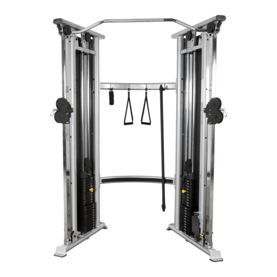
Summary of Contents for Inflight Fitness FT1000
-
Page 3: Important Notices
FT1000 ASSEMBLY INSTRUCTIONS IMPORTANT NOTICES Read all warning labels, the instruction placard and this manual before attempting to use this machine. Always consult your physician and an exercise professional before beginning any exercise program/regimen. Before any test or use check for proper assembly of the machine including (but not limited to): bolts and other hardware fastened properly, cables in pulley grooves and routed correctly. - Page 4 FT1000 PARTS AND HARDWARE PARTS PLATINUM FRAME PARTS L/H Main Frame R/H Main Frame Upper Cross Tube Lower Cross Tube BLACK FRAME PARTS L/H Shroud R/H Shroud CABLES AND PULLEYS - STANDARD 3 ½” Pulleys (10) 4 ½” Pulleys (6)
- Page 5 FT1000 PARTS AND HARDWARE HARDWARE PACKS DESCRIPTION QUANTITY Bolts 3/8” x 4 ¼” 3/8” x 3 ¾” 3/8” x 3 ¼” 3/8” x 2 ¾” 3/8” x 2 ½” 3/8” x 2” 3/8” x 1 ¾” Screws ¼” x ¼” Button Head Screws Washers 3/8”...
-
Page 6: Main Structure Assembly
FT1000 ASSEMBLY INSTRUCTIONS MAIN STRUCTURE ASSEMBLY NOTE: THE L/H AND R/H MAIN FRAMES OF THE FT1000 ARE HEAVY. THE FRAMES ARE TALL AND NARROW AND WILL BE UNSTABLE UNTIL BOLTED TOGETHER WITH THE CROSS BRACES. DO NOT STAND A FRAME UP AND THEN LEAVE IT UNATTENDED. - Page 8 FT1000 ASSEMBLY INSTRUCTIONS CABLE AND TOPWEIGHT ASSEMBLY 2:1 STANDARD ASSEMBLY E. Disassemble the selector stem from each topweight by removing the 7/16” socket head cap screw. Re-assemble each selector stem and topweight to a 2:1 Topweight Bracket using the same 7/16” screw.
-
Page 10: Weight Stack Assembly
FT1000 ASSEMBLY INSTRUCTIONS WEIGHT STACK ASSEMBLY K. Place one weight stack cushion on each Guide Rod and slide down to the base. Apply lubricant to the Guide Rods from the weight stack cushions to the tops of the Guide Rods. - Page 12 FT1000 ASSEMBLY INSTRUCTIONS THE FOLLOWING CABLE ROUTING APPLIES FOR BOTH THE STANDARD 2:1 AND THE 4:1 OPTION FUNCTIONAL TRAINER N. Route the threaded end of the cable over a 3 ½” Pulley. Attach the Pulley, cable, and a Pulley Cover to the angled welded post located above the guide rods using one 3/8”...
-
Page 14: Transfer Labels
FT1000 ASSEMBLY INSTRUCTIONS SHROUDS U. Install the L/H and R/H Shrouds using twenty ¼” flat washers and twenty ¼” screws. The shorter side of the Shroud attaches to the threaded tabs welded onto the round tube at the rear of the machine.


Need help?
Do you have a question about the FT1000 and is the answer not in the manual?
Questions and answers