
Related Manuals for Inflight Fitness CT-MSEC


Summary of Contents for Inflight Fitness CT-MSEC
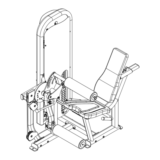
- Page 3 It is strongly recommended that a qualified dealer assemble this CT-MSEC Seated Leg Extension/Leg Curl machine. Should there be any question during assembly contact your authorized Inflight Fitness dealer or call direct to 714 821 4177. Before beginning assembly read this instruction manual thoroughly. Unpack and verify all parts and hardware quantities against the parts and hardware lists.
- Page 4 CT-MSEC PARTS AND HARDWARE PARTS PLATINUM FRAME PARTS Main Upright Seat Frame Base Tube Exercise Arm Frame Support Ass’y Handle Ass’y Guide Rod Bracket Forward Seat Support CUSHION FRAME PARTS Back Support Back Pad Bottom Pad Exercise Pad Ass’y Thigh Pad Ass’y...
- Page 5 CT-MSEC PARTS AND HARDWARE HARDWARE DESCRIPTION QUANTITY Bolts 1/2” x 5 ½” 3/8” x 4 ¾” 3/8” x 4” 3/8” x 3 ¾” 3/8” x 3” w/ blue patch 3/8” x 2 ½” 3/8” x 2 ½” w/ blue patch 3/8”...
- Page 6 CT-MSEC ASSEMBLY INSTRUCTIONS MAIN STRUCTURE ASSEMBLY A1. Assemble the Seat Frame to the Base Tube using 2 – 3/8” x 4 ¾” bolts, 4 – curved washers and 2 – 3/8” nuts. Do not fully tighten the bolts at this time.
- Page 7 1 - Main Upright 2 - 3/8" x 4 3/4' Bolts 4 - Flat Washers 2 - 3/8" Nuts 1 - Seat Frame 1 - Base Tube 2 - 3/8" x 4 3/4" Bolts 4 - Curved Washers 2 - 3/8" Nuts...
- Page 8 CT-MSEC ASSEMBLY INSTRUCTIONS MAIN STRUCTURE ASSEMBLY (continued) B1. Assemble the Exercise Arm Frame Assembly to the assembly made in Step A2 using 2 – 3/8” x 4 ¾” bolts, 4 – curved washers and 2 – 3/8” nuts. Do not fully tighten the bolts at this time.
- Page 9 2 - 3/8" x 2 1/2" Bolts 4 - 3/8" Flat Washers 2 - 3/8" Nuts (Cam hidden for clarity) 1 - Forward Seat Support 1 - 3/8" x 1/2" Bolt w/ blue patch 2 - 3/8" x 3/4" Bolt w/ blue patch 3 - 3/8"...
- Page 10 CT-MSEC ASSEMBLY INSTRUCTIONS PAD ASSEMBLY C1. Assemble the Exercise Pad to the Exercise Arm using 1 – ¾” x 2 ½” Shaft, 1 – 3/8” x 3 ¾” bolt, 2 – 3/8” flat washers and 1 – 3/8” nut. C2. Insert the 1” x 4” Shaft into the bushings of the Thigh Pad Assembly. Assemble the Thigh Pad Assembly to the Exercise Arm Frame Assembly by first pulling the pop pin.
- Page 11 1 - Thigh Pad Ass'y 1 - 1" x 4" Shaft 1 - 1/2" x 5 1/2" Bolt 2 - 1/2" Washers 1 - 1/2" Nut Back Support (Pull pop pin to install) 1 - 3/8" x 1" Bolt w/ blue patch (Depress ratchet lever to install) 1 - Back Pad 2 - 3/8"...
- Page 12 CT-MSEC ASSEMBLY INSTRUCTIONS WEIGHT STACK AND CABLE ASSEMBLY D1. Insert Guide Rods into the base of the Loop Upright. Allow Guide Rods to lean back away from the machine. Place one weight stack cushion on each Guide Rod and slide down to the base. Apply lubricant to the Guide Rods from the weight stack cushions to the tops of the Guide Rods.
- Page 13 1 - 4 1/2" Pulley 1 - Guide Rod Bracket 1 - 3/8" x 2" Bolt 1 - Cam Washer 1 - 4 1/2" Pulley 2 - 3/8" Flat Washers 1 - Triangular Plate 1 - 3/8" Nut 1 - 3/8" x 2" Bolt 2 - 3/8"...
- Page 14 CT-MSEC ASSEMBLY INSTRUCTIONS WEIGHT STACK AND CABLE ASSEMBLY E1. Attach a ball end of the MSEC Lower Cable to the “U”-Bracket. Place a 4 ½” pulley onto the MSEC Upper Cable below the Triangular Bracket and fasten using the “U”- Bracket, 1 –...
- Page 15 1 - Lower Cable 1 - 4 1/2" Pulley 1 - Pulley Bracket 1 - 3/8" x 2" Bolt 2 - 3/8" Flat Washers Cable end in hook 1 - 3/8" Nut 1 - 4 1/2" Pulley 1 - 3/8" x 2 1/4" Bolt 2 - 3/8"...
-
Page 16: Cable Adjustment
CT-MSEC ASSEMBLY INSTRUCTIONS CABLE ADJUSTMENT F1. Adjust cable tension per the following: 1. Raise the exercise arm to the highest leg curl position. 2. Make sure bolt was installed in second weight plate (STEP D5).* 3. Use the cam washer first to remove slack from the cable. - Page 17 Maximum 1" from Cable Adjustment under bolt head to 1. Make sure bolt was installed in bottom of jam nut second weight plate (STEP D5).* 2. Raise the exercise arm to the highest leg curl position. 3. Use the cam washer first to remove slack from the cable.
- Page 18 CT-MSEC ASSEMBLY INSTRUCTIONS SHROUD INSTALLATION F1. Attach five double shroud brackets to the Main Upright using the preinstalled button head screws and washers. F2. Attach the one single side shroud bracket to the Main Upright behind the lower pulley using the pre-installed button head screw and washer.
- Page 19 5 - Double Shroud Brackets 1 - Front Shroud 5 - 1/4" Screws 5 - 1/4" Washers 1 - Rear Shroud 6 - 1/4" Screws 6 - 1/4" Washers 1 - Single Shroud Bracket...
Need help?
Do you have a question about the CT-MSEC and is the answer not in the manual?
Questions and answers