Table of Contents
Advertisement
Advertisement
Table of Contents

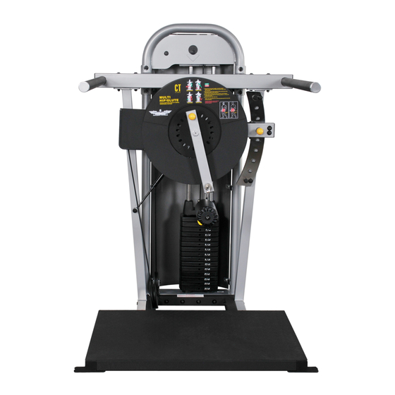
Summary of Contents for Inflight Fitness CT-MHP
- Page 1 For Service Call; (714) 821-4177...
-
Page 3: Important Notices
MHP ASSEMBLY INSTRUCTIONS IMPORTANT NOTICES Read all warning labels, the instruction placard and this manual before attempting to use this machine. Always consult your physician and an exercise professional before beginning any exercise program/regimen. Before any test or use check for proper assembly of the machine including (but not limited to): bolts and other hardware fastened properly, cables in pulley grooves and routed correctly. -
Page 4: Mhp Parts And Hardware
MHP PARTS AND HARDWARE PARTS WHITE / PLATINUM FRAME PARTS Loop Upright L/H Side Support R/H Side Support Handrail Assembly Pulley Arm Exercise Arm Guide Rod Bracket BLACK FRAME PARTS Base Frame Cam Shroud CABLES AND PULLEYS MHP Cable 4 ½” Pulleys (7) MISCELLANEOUS Guide Rods (2) Lube... - Page 5 MHP PARTS AND HARDWARE HARDWARE DESCRIPTION QUANTITY Bolts 3/8” x 6 ½” 3/8” x 5 ¾” 3/8” x 4 ¾” 3/8” x 4 ½” 3/8” x 3 ¾” 3/8” x 3 ½” 3/8” x 2 ¼” 3/8” x 2” 3/8” x 1 ¾” 3/8”...
-
Page 6: Main Structure Assembly
MHP ASSEMBLY INSTRUCTIONS MAIN STRUCTURE ASSEMBLY A. Assemble the Base to the Loop Upright using 6 – 3/8” x 6 ½” bolts, 12 – 3/9” flat washers and 6 – 3/8” nuts. Do not fully tighten the bolts at this time. B. - Page 7 4 - 3 3/4" bolts Chrome Selector Plate 8 - Washers 2 - 1" Bolts 4 - Nuts 2 - Washers Loop Upright Base Frame 4 - 6 1/2" Bolts 8 - Washers 4 - Nuts Handrail Assembly 4 - 4 3/4" Bolts 8 - Curved Washers 4 - Nuts L/H Side Support...
-
Page 8: Exercise Structure Assembly
MHP ASSEMBLY INSTRUCTIONS EXERCISE STRUCTURE ASSEMBLY F. Slide the shaft of the Height Adjust Arm through the bronze bushing in the L/H Side Support and secure using a split shaft collar and 1 - ¼” x ¾” screw. Install the screw into the shaft collar and tighten. G. - Page 9 Nylon Guide 2 - 3/8 x 3 1/4" Buttonhead Bolts 4 - Washers Height Adjust Arm 2 - Nuts Shaft Collar 1 - 1/4" x 3/4" Screw Gas Spring 1 - 1 1/4" Bolt 2 - Washers 1 - Nut Gas Spring 1 - 1 1/2 Bolt 1 - Washer...
-
Page 10: Weight Stack, Cable And Pulley Installation
MHP ASSEMBLY INSTRUCTIONS WEIGHT STACK, CABLE AND PULLEY INSTALLATION K. Insert Guide Rods into the base of the Loop Upright. Allow Guide Rods to lean back away from the machine. Place one weight stack cushion on each Guide Rod and slide down to the base. Apply lubricant to the Guide Rods from the weight stack cushions to the tops of the Guide Rods. - Page 11 Pulley 1 - 1 3/4" Bolt Pulley 2 - Washers Guide Rod Bracket 1 - Nut Cam Washer 1 - 2 1/4" Bolt 2 - Washers 1 - Nut 2 - Guide Rods 2 - Weight Cushions Top Weight and Cable FRONT PLATE HIDDEN FOR CLARITY 15 - 10# Weight Plates 1 - 5 3/4"...
- Page 12 MHP ASSEMBLY INSTRUCTIONS EXERCISE ARM R. Attach the Roller Assembly to the Exercise Arm using 1 - 3/8” x 3/4” bolt and 1 - 3/8” washer. CABLE ADJUSTMENT Note: Before proceeding make sure that all the bolts are tight except for the bolt installed at Step L.
- Page 13 Cable Adjustment (Optional) Aft Shroud 6 - 2 1/2" Buttonhead Bolts 12 - Washers 6 - Nuts Cam Shroud 2 - 3 1/2" Bolts 4 - Washers 2 - Nuts Placard Roller Ass'y Weight Labels 1 - 3/4" Bolt 1 - Washer...


Need help?
Do you have a question about the CT-MHP and is the answer not in the manual?
Questions and answers