Advertisement
Quick Links
Advertisement

Related Manuals for Inflight Fitness Vanguard


Summary of Contents for Inflight Fitness Vanguard
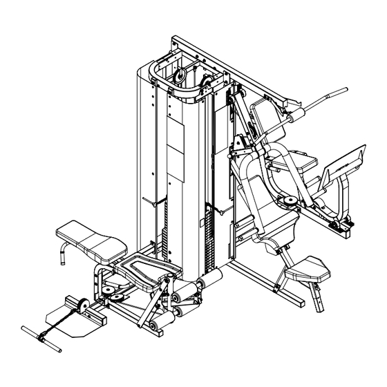
- Page 1 VANGUARD with LEG PRESS OPTION ASSEMBLY MANUAL VANGUARD with LEG PRESS OPTION ASSEMBLY MANUAL...
- Page 2 It is strongly recommended that a qualified dealer assemble this Vanguard exercise machine. Should there be any question during assembly contact your authorized Inflight Fitness dealer or call direct to 714 821 4177. Before beginning assembly read this instruction manual thoroughly. Unpack and verify all parts and hardware quantities against the parts and hardware lists.
- Page 3 VANGUARD/LPO PARTS AND HARDWARE VANGUARD/LPO PARTS AND HARDWARE PARTS HARDWARE DESCRIPTION PLATINUM FRAME PARTS Main Upright Base Tube Mid-Frame Vanguard Hardware Pack (3) Base Frame MEC Lower Attach Top Beam Vanguard LPO Hardware Pack Top Frame Vertical Tubes (2) Low Row Tube...
- Page 4 VANGUARD/LPO ASSEMBLY INSTRUCTIONS NOTE: DO NOT FULLY TIGHTEN BOLTS UNTIL AFTER STEP B3. MAIN STRUCTURE ASSEMBLY Mid-Frame LPO Connector* A1. Assemble the Base Frame to the Main Upright and Base tube using 1 – 3/8” x 3” 2 - 3/8" x 3 1/2" Bolts* bolts, 2 –...
- Page 5 VANGUARD/LPO ASSEMBLY INSTRUCTIONS WARNING: Top Beam Do not put a bolt into this hole 1 - 3/8" x 3" Bolt MAIN STRUCTURE ASSEMBLY 2 - 3/8" x 2 3/4" Bolt 6 - Washers 3 - Nuts B1. Assemble the Top Frame to the Main Upright using 2 – 3/8” x 3” bolts, 4 – 3/8” flat washers and 2 –...
- Page 6 VANGUARD/LPO ASSEMBLY INSTRUCTIONS 2 - Guide Rods 2 - Weight Cushions WEIGHT STACK INSTALLATION 10 - 10lb. Weight Plates 10 - 5lb. Weight Plates C1. Insert 2 - Guide Rods into the two large holes in the Mid Frame near the center of 1 - Top Weight 1 - Angled G.
- Page 7 VANGUARD/LPO ASSEMBLY INSTRUCTIONS LPO STRUCTURE ASSEMBLY D1. Attach the Leg Press Arm to the LPO Seat Frame using 2 – 1” Pillow Block bearings, 4 - 3/8” x 1 ¼” bolts, 8 -3/8” flat washers and 4 – 3/8” nuts. The setscrews are oriented to the outside.
- Page 8 VANGUARD/LPO ASSEMBLY INSTRUCTIONS MEC STATION STRUCTURE ASSEMBLY E1. Attach the two Bearing Flats to the Main MEC Frame using 2 – 3/8” x 4 ½” bolts, 4 – ½” barrel spacers, 4 -3/8” flat washers and 2 – 3/8” nuts.
- Page 9 VANGUARD/LPO ASSEMBLY INSTRUCTIONS 2 - Bearing Brackets 2 - 3/8" x 3" Bolts MPS/MLA STATION STRUCTURE ASSEMBLY 4 - Washers 2 - Nuts F1. Attach the Seat Frame to the Main Upright using 2- 3/8” x 3 ¾” bolts, 4 – 3/8”...
- Page 10 VANGUARD/LPO ASSEMBLY INSTRUCTIONS 1 - 4 1/2" Pulley MPS/MLA/LPO STATION CABLE ASSEMBLY 1 - 1/2" Step Spacer 1 - 3/4" Step Spacer G1. Install the P13-0453 Cable starting from the slot at the end of the Top Beam. Slide 1 - 3/8" x 2 3/4" Bolt...
- Page 11 VANGUARD/LPO ASSEMBLY INSTRUCTIONS Slide Loop of Lanyard down to Top Weight if possible MPS/MLA/LPO STATION CABLE ASSEMBLY (continued) G7. Thread the P13-0458 cable into the threaded boss in the Top Weight. Remember Maximum 1" from to slide the loop of the weight pin lanyard onto the cable/topweight if you have not 1 - 6"...
- Page 12 VANGUARD/LPO ASSEMBLY INSTRUCTIONS MPS/MLA/LPO STATION CABLE ASSEMBLY (continued) G13. Route the P13-0459 cable down to the pulley bracket on the LPO connector. Install a 4 ½” pulley over the cable and install the pulley into the bracket using 1 –...
- Page 13 VANGUARD/LPO ASSEMBLY INSTRUCTIONS 1 - 6" Pulley MEC/LOW ROW STATION CABLE ASSEMBLY 1 - Angle Cable Retainer 1 - 3/8" x 2 3/4" Bolt H1. Thread the P13-0454 cable into the threaded boss in the Top Weight. Remember 2 - Washers...
- Page 14 VANGUARD/LPO ASSEMBLY INSTRUCTIONS MEC/LOW ROW STATION CABLE ASSEMBLY 1 - 4 1/2" Pulleys 1 - 3/8" x 2" Bolts 2 - Washers 2 - 4 1/2" Pulleys H5. Attach the end of the P13-0455 Lower MEC Cable that does not have a ball to the 1 - Nut 1 - 3/8"...
- Page 15 VANGUARD/LPO ASSEMBLY INSTRUCTIONS 1 - 9 x 16 Pad 1 - 9 x 16 Pad 1 - 9 x 16 Pad 2 - 3/8" x 1 1/2" Bolt 1 - 9 x 16 Pad 2 - 3/8" x 1 1/2" Bolt PAD ASSEMBLY 1 - 3/8"...
- Page 16 VANGUARD/LPO ASSEMBLY INSTRUCTIONS 1 - Angle Shroud Bracket* 1 - Angle Shroud Bracket* 1 - 1/4" x 3/4" Screw* 1 - 1/4" x 3/4" Screw* 1 - Flat Shroud* 1 - Flat Shroud* FLAT SHROUD ASSEMBLY 1 - 1/4" Washer* 1 - 1/4"...
- Page 17 VANGUARD/LPO ASSEMBLY INSTRUCTIONS Remove extra screws 1 - Large Curved Shroud* before installing shroud 9 - 1/4 x 3/4" Screws SHROUD AND/OR MEC SUPPORT ASSEMBLY 9 - 1/4" Washers NOTE: If you are not installing shrouds proceed to Step K2. Then proceed to pages 34 and 35 for placard installation.
- Page 18 VANGUARD/LPO ASSEMBLY INSTRUCTIONS 1 - Flat Shroud* 1 - Flat Shroud* 8 - 1/4" x 3/4" Screws(2*) SHROUD ASSEMBLY CONTINUED 8 - 1/4" x 3/4" Screws(2*) 1 - Small Curved Shroud* 8 - 1/4" Washers(2*) 1 - Small Curved Shroud* 8 - 1/4"...
- Page 19 VANGUARD/LPO ASSEMBLY INSTRUCTIONS 1 - LH Lat Bar Holder Leg Extension/Curl Placard 1 - RH Lat Bar Holder Bicep/Low Row Placard PLACARD, LABEL AND ACCESSORY ASSEMBLY 2 - 3/8" x 3" Bolts 4 - Washers 2 - Nuts M1. Attach the L/H and R/H Lat Bar Holders using 2 – 3/8” x 3” Bolts, 4 – 3/8” Washers and 2 –...
- Page 20 VANGUARD/LPO ASSEMBLY INSTRUCTIONS CABLE TENSION ADJUSTMENT USE CAM WASHER TO ADJUST CABLE TENSION N1. Adjust the cable tension on the MEC station by loosening the jam nut on the threaded stop behind the MEC exercise arm and threading the stop in or out. Re- USE THREADED STOP TO tighten the jam nut.
Need help?
Do you have a question about the Vanguard and is the answer not in the manual?
Questions and answers