Advertisement
Quick Links
Advertisement

Related Manuals for Inflight Fitness SMITH MACHINE


Summary of Contents for Inflight Fitness SMITH MACHINE
-
Page 3: Important Notices
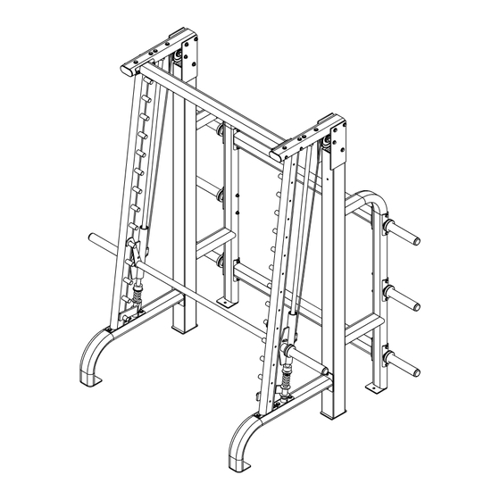
SMITH MACHINE ASSEMBLY INSTRUCTIONS IMPORTANT NOTICES Read all warning labels and this manual before attempting to use this machine. Always consult your physician and an exercise professional before beginning any exercise program/regimen. Before any test or use check for proper assembly of the machine including (but not limited to): bolts and other hardware fastened properly, cables in pulley grooves and routed correctly. - Page 4 SMITH MACHINE PARTS AND HARDWARE PARTS PLATINUM FRAME PARTS Side Supports (2) Top Tubes (2) Cross Beams (3) Vertical Tube L/H Vertical Tube R/H Base Tube L/H Guide Rod Brackets (4) Base Tube R/H BLACK FRAME PARTS L/H Safety Stop...
- Page 5 SMITH MACHINE PARTS AND HARDWARE HARDWARE DESCRIPTION QUANTITY Bolts 3/8” x 5” 3/8” x 4 3/4” 3/8” x 2 ¾” Washers and Spacers 3/8” Flat Washers 3/8” Curved Washers 1” Washers 1 ½” Step Spacers Nuts 3/8” Nuts...
-
Page 6: Main Structure Assembly
Weight Horns using 8 – 3/8” x 5” bolts, 16 – 3/8” curved washers, and 8 – 3/8” nuts. The Inflight Fitness labels on the Side Supports face to the outside of the machine. The Upper Cross Beam is to be assembled with the Maximum Weight label facing forward to the inside of the machine. - Page 7 2- Cables 1 - L/H Side Support 2 - Counterweights 1 - R/H Side Support 2 - Pulleys 1 - Upper Beam w/ label 4 - 5" Bolts 1 - Lower Beam 2 - 1 1/2" Spacers 4 - Weight Horns 2 - Nuts 8 - 5"...
- Page 8 SMITH MACHINE ASSEMBLY INSTRUCTIONS GUIDED WEIGHT BAR INSTALLATION F. Insert the Guide Rods into the Bottom Guide Rod Brackets. Slide the L/H and R/H Safety Stops onto the Guide Rods to the bottom. Point the hook ends toward the center of the machine. Then slide a Spring down each rod to the Safety Stop, followed by a 1”...
- Page 9 2 - Guide Rod Brackets 1 - L/H Vertical Tube 1 - R/H Vertical Tube 4 - 2 3/4" Bolts 8 - Washers 4 - Nuts 1 - Weight Bar Ass'y Clevis Pin E-Clip 2 - Guide Rods 1 - L/H Safety Stop 1 - R/H Safety Stop 2 - Springs 2 - Washers...
-
Page 10: Final Assembly
SMITH MACHINE ASSEMBLY INSTRUCTIONS FINAL ASSEMBLY K. Attach the last Cross Beam to the Top Tubes using 4 – 3/8” x 43/4” bolts, 8 – 3/8” curved washers, and 4 – 3/8” nuts. L. Attach the Top Tubes/Cross Beam to the Vertical Tubes using 4 – 3/8” x 2 3/4”... - Page 11 4 - 5" Bolts 1 - Cross Beam 8 - 2 3/4" Bolts 2 - Top Beams 2 - 5" Bolts 24 - Washers 4 - 4 3/4" Bolts 4 - Washers 12 - Nuts 8 - Curved Washers 2 - Nuts 4 - Nuts Remove bolts supporting the counterweights and...
Need help?
Do you have a question about the SMITH MACHINE and is the answer not in the manual?
Questions and answers