Advertisement
Quick Links
Advertisement

Subscribe to Our Youtube Channel
Related Manuals for Inflight Fitness CT-ILPC


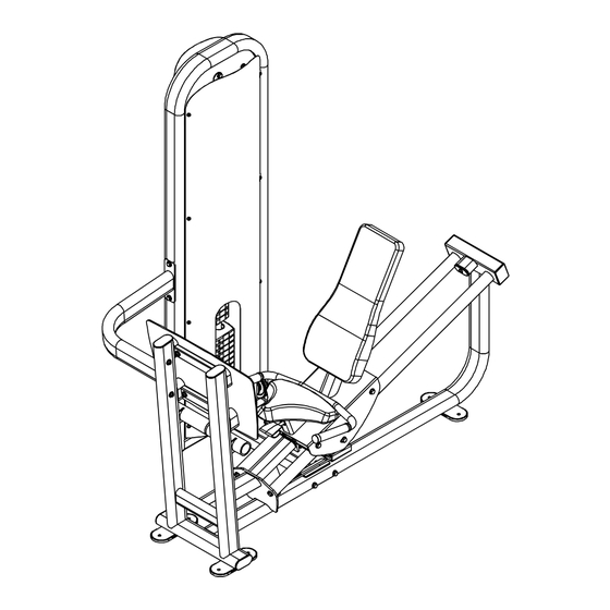
Summary of Contents for Inflight Fitness CT-ILPC
-
Page 2: Important Notices
It is strongly recommended that a qualified dealer assemble this CT-ILPC Incline Leg Press/ Calf Raise Should there be any question during assembly contact your authorized Inflight Fitness dealer or call direct to 714 821 4177. Before beginning assembly read this instruction manual thoroughly. Unpack and verify all parts and hardware quantities against the parts and hardware lists. - Page 3 CT-ILPC PARTS AND HARDWARE PARTS PLATINUM FRAME PARTS Main Upright Seat Frame Base Tube Plate Guide Rod Bracket Handle Ass’y PLATINUM FRAME PARTS Footplate CUSHION FRAME PARTS Back Pad Bottom Pad CABLES AND PULLEYS 4 ½” Pulleys (5) ILPC Cable...
- Page 4 CT-ILPC PARTS AND HARDWARE HARDWARE DESCRIPTION QUANTITY Bolts Washers Flat Washers Cam Washer Nuts and Miscellaneous Flat Head Screws...
-
Page 5: Main Structure Assembly
CT-ILPC ASSEMBLY INSTRUCTIONS MAIN STRUCTURE ASSEMBLY A1. Assemble the Seat Frame to the Base Tube and Main Upright using 4 – 3/8” x 4 ¾” bolts, 4 – curved washers, 4 – flat washers and 4 – 3/8” nuts. Do not fully tighten the bolts at this time. - Page 7 CT-ILPC ASSEMBLY INSTRUCTIONS PAD AND FRAME PARTS B1. Assemble the Footplate to the Seat Frame using 4 – 3/8” x 1 ¾” flat head screws, 4 – flat washers and 4 – 3/8” nuts. B2. Assemble the Handle Assembly to the sliding Seat Sled Assembly using 2 – 3/8” x 1”...
- Page 9 CT-ILPC ASSEMBLY INSTRUCTIONS WEIGHT STACK AND CABLE ASSEMBLY C1. Insert Guide Rods into the base of the Loop Upright. Allow Guide Rods to lean back away from the machine. Place one weight stack cushion on each Guide Rod and slide down to the base. Apply lubricant to the Guide Rods from the weight stack cushions to the tops of the Guide Rods.
- Page 11 CT-ILPC ASSEMBLY INSTRUCTIONS CABLE ASSEMBLY (continued) D1. Route the cable down between the plates welded to the base of the Loop Upright. and 1 welded on the base of the Seat Frame near the Base Tube. Fasten the pulley using s, and 1 -3/8 nut.
-
Page 13: Shroud Installation
CT-ILPC ASSEMBLY INSTRUCTIONS SHROUD INSTALLATION E1. Attach the two offset double shroud brackets to the Main Upright using the preinstalled button head screws and washers. E1. Attach five double shroud brackets to the Main Upright using the preinstalled button head screws and washers.
Need help?
Do you have a question about the CT-ILPC and is the answer not in the manual?
Questions and answers