Table of Contents
Advertisement
Quick Links
A S S E M B L Y M A N U A L
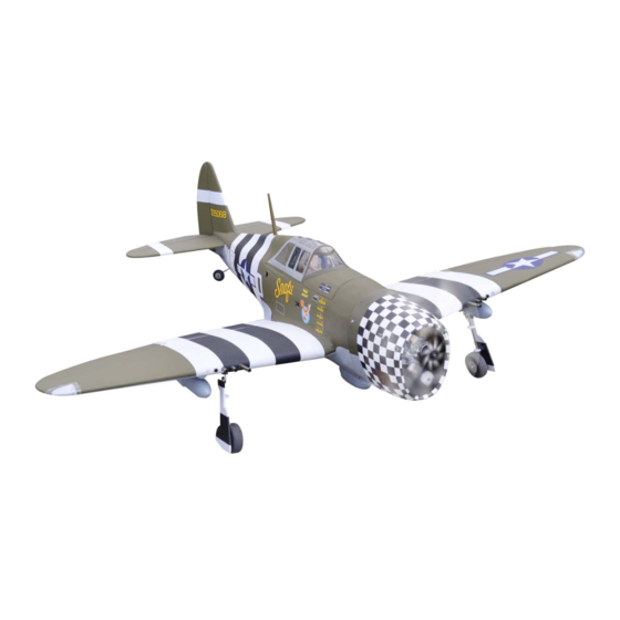
P - 4 7 G T H U N D E R B O R T
SNAFU 6 3 " W I N G 2 0 c c
" Graphics and speciications may change without notice " .
Code:
SEA207N
Speciications:
Wingspan---------------63.0 in (160 cm).
Wing area----------------728.5 sq.in (47.0 sq.dm).
Weight-------------------9.3 - 9.9 lbs (4.2 - 4.5 kg).
Length-------------------51.8 in (131.5cm).
Engine-------------------0.61 - 0.91 cu.in----2 stroke.
...................................0.91- 1.00 cu.in----4 stroke.
...................................15-20cc gasoline engine .
Radio---------------------6 channels with 7 servos.
Electric conversion: Optional.
1
Advertisement
Table of Contents

Related Manuals for Seagull Models SEA207N


Summary of Contents for Seagull Models SEA207N
- Page 1 P - 4 7 G T H U N D E R B O R T SNAFU 6 3 " W I N G 2 0 c c “ Graphics and speciications may change without notice ” . Code: SEA207N Speciications: Wingspan---------------63.0 in (160 cm). Wing area----------------728.5 sq.in (47.0 sq.dm).
-
Page 2: Kit Contents
Instruction Manual. P47 SNAFU INTRODUCTION. hank you for choosing the P47 SNAFU ARF by SG MODELS. he P47 SNAFU was de- signed with the intermediate/advanced sport lyer in mind. It is a semi scale airplane which is easy to ly and quick to assemble. he airframe is conventionally built using balsa, plywood to make it stronger than the average ARF, yet the design allows the aeroplane to be kept light. -
Page 3: Additional Items Required
HINGING THE FLAP. KIT CONTENTS. SEA207 P47 SNAFU Note : he control surfaces, including the ai- SEA20701 Fuselage lerons, elevators, and rudder, are prehinged SEA20702 Wing set with hinges installed, but the hinges are not glued in place. It is imperative that you prop- SEA20703 Tail set erly adhere the hinges in place per the steps SEA20704 Canopy... -
Page 4: Hinging The Aileron
Instruction Manual. P47 SNAFU 4) Delect the lap and completely saturate 8) Ater both lap are securely hinged, irmly each hinge with thin C/A glue. he lap front grasp the wing panel and lap to make sure surface should lightly contact the wing dur- the hinges are securely glued and cannot ing this procedure. -
Page 5: Hinging The Elevators
5) Turn the wing panel over and delect the aileron in the opposite direction from the opposite side. Apply thin C/A glue to each hinge, making sure that the C/A penetrates into both the aileron and wing panel. 6) Using C/A remover/debonder and a pa- per towel, remove any excess C/A glue that Hinge. -
Page 6: Hinging The Rudder
Instruction Manual. P47 SNAFU HINGING THE RUDDER. INSTALL FLAP CONTROL HORN. Glue the rudder hinges in place using Install the lap control horn using the the same techniques used to hinge the ai- same method as same as the aileron con- lerons. -
Page 7: Installing The Fuselage Servos
INSTALLING THE FUSELAGE SERVOS. Elevator iberglass control horn. Because the size of servos difer, you may need to adjust the size of the precut opening in the mount. he notch in the sides of the mount allow the servo lead to pass through. -
Page 8: Installing The Stopper Assembly
Instruction Manual. P47 SNAFU INSTALLING THE RECEIVER SWITCH. Install the switch into the precut hole in the side, in the fuselage. 3/32” Hole. Switch. INSTALLING THE STOPPER ASSEMBLY. 1) Using a modeling knife, carefully cut of the rear portion of one of the 3 nylon tubes leaving 1/2”... -
Page 9: Fuel Tank Installation
7) Slide the fuel tank into the fuselage. Guide the lines from the tank through the hole in the irewall. 8) Use plywood template to hold in place the fuel tank with C/A glue to secure the fuel tank inside the fuselage. Vent tube. -
Page 10: Engine Mount Installation
Instruction Manual. P47 SNAFU MOUNTING THE ENGINE - 2 stroke. 1) Position the engine with the drive washer (145mm) forward of the irewall as shown. Blow through one of the lines to ensure the fuel lines have not become kinked inside the fuel tank compartment. - Page 11 4) On the ire wall has the location for the 8) Reinstall the servo horn by sliding the throttle pusshrod tube (pre-drill). connector over the pushrod wire. Center the throttle stick and trim and install the 5) Slide the pushrod tube in the irewall servo horn perpendicular to the servo and guide it through the fuel tank mount.
- Page 12 Instruction Manual. P47 SNAFU Drill hole 3mm. Drill hole. C/A glue. Cut. Knife.
- Page 13 2) While keeping the back edge of the cowl lush with the marks, align the front of the cowl with the crankshat of the engine. he front of the cowl should be positioned so the crankshat is in nearly the middle of the cowl opening.
- Page 14 Instruction Manual. P47 SNAFU MOUNTING THE ENGINE 15cc. 1) Position the engine with the drive washer (145mm) forward of the irewall as shown. Pushrod wire. 145mm. 2) Use a pin drill and 4mm drill bit to drill a small indentation in the mount for the engine mounting screw.
- Page 15 COWLING. 1) Slide the iberglass cowl over the en- gine and line up the back edge of the cowl with the marks you made on the fuselage then trim and cut as shown. 2) While keeping the back edge of the cowl lush with the marks, align the front of the cowl with the crankshat of the engine.
- Page 16 Instruction Manual. P47 SNAFU 145mm. 2) Use a pin drill and 4mm drill bit to drill a small indentation in the mount for the engine mounting screw. 3) Use a drill to drill the four holes in the engine mount rails. 4) On the ire wall has the location for the throttle pusshrod tube (pre-drill).
- Page 17 3x10mm. Trim and cut. Needle valve. 3) Install the muler and muler extension onto the engine and make the cutout in the cowl for muler clearance. Connect the fuel and pressure lines to the carburetor, muler and fuel iller valve. Secure the cowl to fuse- lage using the M3x10mm screws.
- Page 18 Instruction Manual. P47 SNAFU 2) Recommen the items necessary to in- stall the electric power conversion parts included with your model. - Model size: .75-.90 size models - Motor: 50mm 310 rev per volt - Propeller: 15x10 ~ 16x10 - ESC: 80A - Lipo Batteries: 8 cell 5200mA 3) Attach the electric motor box to the irewall suitable with the cross lines...
-
Page 19: Installing The Propeller
M3x12mm. Tie wraps. Epoxy. Battery. 145mm. Balsa stick. INSTALLING THE PROPELLER. Epoxy. 6) Attach the speed control to the side of the motor box using two-sided tape and tie wraps. Connect the appropriate leads from the speed control to the mo- tor. -
Page 20: Installing The Aileron Servos
Instruction Manual. P47 SNAFU 3) Use drill bit in a pin vise to drill the mouting holes in the blocks. INSTALLING THE AILERON SERVOS. 4) Apply 2-3 drops of thin C/A to each of the mounting holes. Allow the C/A to cure without using accelerator. - Page 21 7) Apply 1-2 drops of thin C/A to each of the mounting tabs. Allow the C/A to cure without using accelerator. 9) Set the aileron hatch in place and use a C/A glue. Phillips screw driver to install it with four wood screws.
-
Page 22: Aileron Pushrod Installation
Instruction Manual. P47 SNAFU AILERON PUSHROD INSTALLATION. 60mm. Cut. Wing. Hex nut. M2 clevis. Fuel tubing. INSTALLING THE FLAP PUSHROD. Repeat the procedure for the aileron pushrod. 50mm. C/A glue. - Page 23 Flap. Hex nut. M2 clevis. Fuel tubing. INSTALLING RETRACTABLE LANDING GEAR. Locate items necessary to install Sprin Landing Gear. You use this fork set JP ER-120-84degree. 3x20mm.
- Page 24 Instruction Manual. P47 SNAFU 3x4mm. 3x10mm.
- Page 25 Collar. M3x4mm.
- Page 26 Instruction Manual. P47 SNAFU Insert bomb onto the wings. Epoxy. Cut. Cut. Epoxy.
-
Page 27: Installing The Horizontal Stabilizer
Draw center line Epoxy. 2) Using a modeling knife, carefully re- move the covering at mounting slot of horizontal stabilizer ( both side of fuse- lage). 3) Slide the stabilizer into place in the precut slot in the rear of the fuselage. he stabilizer should be pushed irmly against the front of the slot. -
Page 28: Installing Vertical Stabilizer
Instruction Manual. P47 SNAFU 7) When you are sure that everything is aligned correctly, mix up a generous amount of 30 Minute Epoxy. Apply a thin layer to the top and bottom of the stabi- lizer mounting area and to the stabilizer mounting platform sides in the fuselage. -
Page 29: Elevator Pushrod Installation
C/A glue. Fill Epoxy. Hinge. 2) While holding the vertical stabilizer irmly in place, use a pen and draw a 4) When you are sure that everything is line on each side of the vertical stabilizer aligned correctly, mix up a generous where it meets the top of the fuselage. -
Page 30: Rudder Pushrod Installation
Instruction Manual. P47 SNAFU 2) Install the elevator control horn using the same method as with the aileron con- trol horns. 3) Position the elevator control horn on the both side of elevator. RUDDER PUSHROD INSTALLATION. Elevator control horn. 1) Locate items necessaryto install rud- der pushrod. -
Page 31: Mounting The Tail Wheel
Screw. MOUNTING THE TAIL WHEEL. 1) Locate the items necessary to install tail gear. M2 clevis. Fuel tubing. Hex nut. Tail gear. - Page 32 Instruction Manual. P47 SNAFU Fuel tubing. M2 clevis. Hex nut. Insert fuel tank onto the wings. 3x15mm. Cut. C/A glue. 3x15mm.
- Page 33 3) Position the pilot igure on the canopy loor as show. Locate the oval shaped on the canopy loor and remove the cover- ing. Use epoxy to glue this into the base of the pilot igure and glue the cockpit panel in place with C/A glue, please see pictures as shown.
-
Page 34: Apply The Decals
Instruction Manual. P47 SNAFU APPLY THE DECALS. Remove covering to see hole. 1) If all the decals are precut and ready to stick. Please be certain the model is clean and free from oily ingerprints and dust. Position decal on the model where de- sired, using the photos on the box and aid in their location. - Page 35 Epoxy. Epoxy. Wing bolt. ATTACHMENT WING- FUSELAGE. Attach the aluminum tube into fuselage. Wing tube. Wing bolt. BALANCING. 1) It is critical that your airplane be Insert two wing panels as pictures below. balanced correctly. Improper balance will cause your plane to lose control and crash.
-
Page 36: Control Throws
Instruction Manual. P47 SNAFU 2) Mount the wing to the fuselage. Using *If possible, irst attempt to balance the a couple of pieces of masking tape, place model by changing the position of the re- them on the bottom side of the wing ceiver battery and receiver. -
Page 38: Flight Preparation
Instruction Manual. P47 SNAFU FLIGHT PREPARATION. PREFLIGHT CHECK. 1) Completely charge your trans- Check the operation and direction mitter and receiver batteries before of the elevator, rudder, ailerons and your irst day of lying. throttle. 2) Check every bolt and every A) Plug in your radio system per the glue joint in the P47 SNAFU to en- manufacturer’s instructions and turn... - Page 39 If you have any queries, or are interested in our products, please feel free to contact us Factory : 12/101A - Hamlet 4 - Le Van Khuong Street - Dong hanh Ward - Hoc Mon District - Ho Chi Minh City - Viet Nam. Oice : 62/8 Ngo Tat To Street - Ward 19 - Binh hanh District - Ho Chi Minh City - Viet Nam Phone : 848 - 37114542 or 848- 36018777...
Need help?
Do you have a question about the SEA207N and is the answer not in the manual?
Questions and answers