Sun Microsystems Ultra 60 Service Manual
Hide thumbs
Also See for Ultra 60:
- Service manual (240 pages) ,
- Manual (66 pages) ,
- Upgrade manual (28 pages)

Related Manuals for Sun Microsystems Ultra 60


Summary of Contents for Sun Microsystems Ultra 60
- Page 1 Ultra 60 Service ™ ™ Manual Sun Microsystems, Inc. 901 San Antonio Road Palo Alto, CA 94303-4900 U.S.A. 650-960-1300 Part No. 805-1709-12 Revision A, August 2001 Send comments about this document to: docfeedback@sun.com...
- Page 2 Sun, Sun Microsystems, le logo Sun, AnswerBook2, docs.sun.com, et Solaris sont des marques de fabrique ou des marques déposées, ou marques de service, de Sun Microsystems, Inc. aux Etats-Unis et dans d’autres pays. Toutes les marques SPARC sont utilisées sous licence et sont des marques de fabrique ou des marques déposées de SPARC International, Inc.
-
Page 3: Table Of Contents
Contents Preface xvii Product Description 1-1 I/O Devices 1-3 System Unit Features 1-3 System Unit Components 1-5 SunVTS Overview 2-1 SunVTS Description 2-1 SunVTS Operation 2-2 Power-On Self-Test 3-1 POST Overview 3-2 Pre-POST Preparation 3-2 3.2.1 Setting Up a Tip Connection 3-3 3.2.2 Verifying the Baud Rate 3-4 Initializing POST 3-5... - Page 4 3.4.3 POST Progress and Error Reporting 3-18 Bypassing POST 3-21 Additional Keyboard Control Commands 3-22 System and Keyboard LEDs 3-22 Initializing Motherboard POST 3-23 Troubleshooting Procedures 4-1 Power-On Failure 4-2 Video Output Failure 4-3 Disk Drive or CD-ROM Drive Failure 4-3 Power Supply Test 4-5 DIMM Failure 4-7 OpenBoot PROM On-Board Diagnostics 4-8...
- Page 5 4.7.10 NVRAM 4-22 4.7.11 Audio 4-22 4.7.12 SCSI 4-23 4.7.13 All Above 4-23 Safety and Tool Requirements 5-1 Safety Requirements 5-2 Symbols 5-2 Safety Precautions 5-3 5.3.1 Modification to Equipment 5-3 5.3.2 Placement of a Sun Product 5-3 5.3.3 Power Cord Connection 5-3 5.3.4 Electrostatic Discharge 5-4 5.3.5...
- Page 6 PCI Fan Assembly 8-5 8.2.1 Removing the PCI Fan Assembly 8-5 8.2.2 Replacing the PCI Fan Assembly 8-6 Hard Drive Bay With SCSI Assembly 8-7 8.3.1 Removing the SCSI Drive Bay 8-7 8.3.2 Replacing the SCSI Drive Bay 8-9 Cable Assemblies 8-11 8.4.1 Removing the Peripheral Power Cable Assembly 8-11 8.4.2...
- Page 7 8.10.1 Removing the Shroud Assembly 8-38 8.10.2 Replacing the Shroud Assembly 8-39 Storage Devices 9-1 Hard Drive 9-2 9.1.1 Removing a Hard Drive 9-2 9.1.2 Replacing a Hard Drive 9-3 Removable Media Assembly Drive 9-4 9.2.1 Removing the RMA 9-4 9.2.2 Removing the CD-ROM Drive or Any X-Option Tape Drive 9-6 9.2.3...
- Page 8 10.4.2 Replacing the UPA Graphics Card 10-11 10.5 DIMM 10-12 10.5.1 Removing a DIMM 10-13 10.5.2 Replacing a DIMM 10-15 10.6 Audio Card 10-16 10.6.1 Removing the Audio Card 10-16 10.6.2 Replacing the Audio Card 10-18 10.7 Motherboard 10-19 10.7.1 Removing a Motherboard 10-20 10.7.2 Replacing a Motherboard 10-23...
- Page 9 C. Functional Description C-1 System Unit C-2 C.1.1 UPA Interconnect C-4 C.1.2 System Controller C-5 C.1.3 PCI Bus C-6 C.1.4 EBus2 Devices C-7 C.1.5 UltraSPARC II Processor C-8 C.1.6 Memory System C-9 C.1.7 Graphics and Imaging C-14 C.1.8 Peripherals C-15 C.1.9 Other RMA Storage Device X-Options C-19 C.1.10 Keyboard and Mouse, Diskette, and Parallel Port C-19...
- Page 10 Energy Star Software Support C-48 Glossary G-1 Index ix-1 Contents...
- Page 11 Figures Ultra 60 Desktop Workstation 1-2 FIGURE 1-1 System Unit Front View 1-4 FIGURE 1-2 System Unit Rear View 1-5 FIGURE 1-3 Setting Up a TIP Connection 3-3 FIGURE 3-1 Sun Type-5 Keyboard 3-5 FIGURE 3-2 Power Supply Connector J2901 4-6...
- Page 12 Removing and Replacing the RMA EMI Filler Panel 8-15 FIGURE 8-6 Removing and Replacing the Chassis Foot 8-16 FIGURE 8-7 Removing and Replacing the Speaker Assembly 8-18 FIGURE 8-8 System Unit Power-Off (Front Panel) 8-20 FIGURE 8-9 Lock Block Location 8-20 FIGURE 8-10 Removing the Side Access Cover 8-21 FIGURE 8-11...
- Page 13 MII Connector Pin Configuration B-14 FIGURE B-7 UPA Graphics Card Connector Pin Configuration B-16 FIGURE B-8 Ultra 60 System Unit Functional Block Diagram C-3 FIGURE C-1 UPA Address and Data Buses Functional Block Diagram C-5 FIGURE C-2 Memory System Functional Block Diagram C-10...
- Page 14 Figures...
- Page 15 Tables Supported I/O Devices 1-3 TABLE 1-1 System Unit Replaceable Components 1-6 TABLE 1-2 SunVTS Documentation 2-2 TABLE 2-1 Diag-Level Switch Settings 3-2 TABLE 3-1 Keyboard LED Patterns 3-21 TABLE 3-2 Internal Drives Identification 4-4 TABLE 4-1 Power Supply Connector J2901 Pin Description TABLE 4-2 Power Supply Connector J2902 Pin Description 4-6 TABLE 4-3...
- Page 16 UltraSCSI Connector Pin Assignments B-7 TABLE B-4 Audio Connector Line Assignment B-11 TABLE B-5 Parallel Port Connector Pin Assignments B-12 TABLE B-6 MII Connector Pin Assignments B-14 TABLE B-7 UPA Graphics Card Connector Pin Assignments B-16 TABLE B-8 UPA Port Identification Assignments C-4 TABLE C-1 DIMM Bank-to-U-Number Mapping C-13 TABLE C-2...
-
Page 17: Preface
(ASPs), and advanced computer system end users who have experience troubleshooting and replacing hardware. The revision of the Sun Ultra 60 Service Manual provided here is the latest revision of the document, and includes information that may be different from that contained in the service documentation originally shipped with the Sun Ultra 60 system. - Page 18 Provides a listing of acronyms, terms, and definitions. Index Provides a quick reference to specific topics. UNIX Commands ® This document may not contain information on basic UNIX commands and procedures. xviii Sun Ultra 60 Service Manual • August 2001...
-
Page 19: Typographic Conventions
See one or more of the following for this information: Solaris 2.x Handbook for SMCC Peripherals. ™ ™ AnswerBook online documentation for the Solaris 2.x software environment. Other software documentation that you received with your system. Typographic Conventions Typographic Conventions TABLE P-2 Typeface or Symbol Meaning... - Page 20 Shell Prompts TABLE P-3 Shell Prompt C shell superuser machine_name# Bourne shell and Korn shell Bourne shell and Korn shell superuser xx Sun Ultra 60 Service Manual • August 2001...
-
Page 21: Related Documents
Related Documents Related Documents TABLE P-4 Application Title Part Number Configuration Sun Ultra 60 System Reference 802-4147 Manual Configuration Solaris Handbook for SMCC 802-7675 Peripherals Diagnostics SunVTS 2.0 User’s Guide 802-5331 Diagnostics SunVTS 2.0 Test Reference 802-5330 Manual Diagnostics SunVTS 2.0 Quick Reference... - Page 22 Fatbrain.com, an Internet professional bookstore, stocks select product documentation from Sun Microsystems, Inc. For a list of documents and how to order them, visit the Sun Documentation Center on Fatbrain.com at: http://www.fatbrain.com/documentation/sun xxii Sun Ultra 60 Service Manual • August 2001...
- Page 23 Sun Welcomes Your Comments Sun is interested in improving its documentation and welcomes your comments and suggestions. You can email your comments to Sun at: docfeedback@sun.com Please include the part number (805-1709-12) of your document in the subject line of your email.
- Page 24 Sun Ultra 60 Service Manual • August 2001...
-
Page 25: Product Description
C H A P T E R Product Description The Ultra 60 desktop workstation is a multiprocessor device that uses the family of ™ UltraSPARC processors. It supports high-performance processing and high-performance graphics. illustrates the Ultra 60 desktop workstation. FIGURE 1-1... -
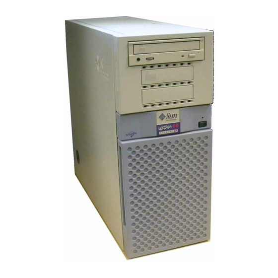
Page 26: Figure 1-1 Ultra 60 Desktop Workstation
System unit Monitor (24-inch optional) Keyboard Mouse/pad Ultra 60 Desktop Workstation FIGURE 1-1 Sun Ultra 60 Service Manual • August 2001... -
Page 27: I/O Devices
I/O Devices The Ultra 60 desktop workstation uses the I/O devices listed in TABLE 1-1 Supported I/O Devices TABLE 1-1 I/O Devices Description 20-inch (51-cm) 1152 x 900 resolution, 76- or 66-Hz refresh rate, 84 dots per inch color monitor... -
Page 28: Figure 1-2 System Unit Front View
Centronics-compatible parallel port interface with extended capability port (ECP) support. Modular audio interface. CD-ROM drive (or tape drive) Power LED Diskette drive Second 3.5-inch drive bay Power On/Standby switch System Unit Front View FIGURE 1-2 Sun Ultra 60 Service Manual • August 2001... -
Page 29: System Unit Components
Note – Removal and replacement of selected system unit components are also illustrated with photographs and audio/visual instructions on the Sun Ultra 60 ShowMe How Multimedia Documentation, part number 704-5886. Chapter 1 Product Description... - Page 30 Diskette drive cable Diskette drive cable Manual eject floppy Diskette drive, 3.5-inch, MS-DOS compatible EMI filler panel CD-ROM drive filler panel EMI filler panel Diskette drive filler panel 16-Mbyte DIMM 60-ns, 16-Mbyte DIMM Sun Ultra 60 Service Manual • August 2001...
- Page 31 System Unit Replaceable Components (Continued) TABLE 1-2 Component Description 32-Mbyte DIMM 60-ns, 32-Mbyte DIMM 64-Mbyte DIMM 60-ns, 64-Mbyte DIMM 128-Mbyte DIMM 60-ns, 128-Mbyte DIMM NVRAM/TOD Time of day, 48T59, with carrier CD-ROM drive 12X-speed CD-ROM drive, 644-Mbyte SunCD™ 4-mm tape drive 4-Gbyte/8-Gbyte, 4-mm tape drive, DDS-2 4-mm tape drive 12-Gbyte/24-Gbyte, 4-mm tape drive, DDS-3...
- Page 32 Sun Ultra 60 Service Manual • August 2001...
-
Page 33: Sunvts Overview
C H A P T E R SunVTS Overview ™ This chapter contains an overview of the SunVTS diagnostic tool. This chapter contains the following topics: SunVTS Description—page 2-1 SunVTS Operation—page 2-2 SunVTS Description The SunVTS software executes multiple diagnostic hardware tests from a single user interface. -
Page 34: Sunvts Operation
SunVTS Test Reference Manual 802-7300 Describes each SunVTS test; provides various test options and command line arguments SunVTS Quick Reference Card 802-7301 Provides overview of vtsui interface features Sun Ultra 60 Service Manual • August 2001... -
Page 35: Power-On Self-Test
C H A P T E R Power-On Self-Test This chapter describes how to initiate power-on self-test (POST) diagnostics. The examples given in this chapter are representative, details of actual test results may be different, depending on system configurations. This chapter contains the following topics: POST Overview—page 3-2 Pre-POST Preparation—page 3-2 Initializing POST—page 3-5... -
Page 36: Post Overview
If a terminal or a monitor is not connected to serial port A (default port) of a workstation or server to be tested, the keyboard LEDs are used to determine error conditions. See Section 3.7, “System and Keyboard LEDs” on page 3-22 Sun Ultra 60 Service Manual • August 2001... -
Page 37: Setting Up A Tip Connection
3.2.1 Setting Up a Tip Connection A tip connection enables a remote shell window to be used as a terminal to display test data of a system being tested. Serial port A or serial port B of a tested system unit is used to establish the tip connection between the system unit being tested and another Sun workstation monitor or TTY-type terminal. -
Page 38: Verifying The Baud Rate
2. Type eeprom. 3. Verify the following serial port default settings as follows: ttyb-mode = 9600,8,n,1 ttya-mode = 9600,8,n,1 Note – Ensure that the settings are consistent with TTY-type terminal or workstation monitor settings. Sun Ultra 60 Service Manual • August 2001... -
Page 39: Initializing Post
Initializing POST POST is initilized in two ways: By setting the diag-switch? to true and the diag-level to max or min, followed by power cycling the system unit By simultaneously pressing the keyboard Stop and D keys while power is applied to the system unit To set the diag-switch? to true and power cycle the system unit: 1. -
Page 40: Maximum And Minimum Levels Of Post
Section 3.4.2, “diag-level Variable Set to min” on page 3-14. To set the diag-level variable to min, type: ok setenv diag-level min To return to the default setting ok setenv diag-level max Sun Ultra 60 Service Manual • August 2001... -
Page 41: Diag-Level Variable Set To Max
A POST output with the diag-level variable set to max diag-level Variable Set to max CODE EXAMPLE 3-1 Executing Power On SelfTest 0> 0>@(#) Sun Ultra 60(UltraSPARC-II 2-way) UPA/PCI POST x.x.x xx/xx/xxxx xx:xx PM 0>INFO: Processor 0 is master. 0> 0> <00> Init System BSS 0>... - Page 42 0> <00> Memory Addr w/ Ecache Test 0>INFO:128MB Bank 0 0>INFO: 0MB Bank 1 0>INFO: 0MB Bank 2 0>INFO: 0MB Bank 3 0> <00> Block Memory Addr Test 0>INFO:128MB Bank 0 0>INFO: 0MB Bank 1 Sun Ultra 60 Service Manual • August 2001...
- Page 43 diag-level Variable Set to max (Continued) CODE EXAMPLE 3-1 0>INFO: 0MB Bank 2 0>INFO: 0MB Bank 3 0> <00> ECC Memory Addr Test 0>INFO:128MB Bank 0 0>INFO: 0MB Bank 1 0>INFO: 0MB Bank 2 0>INFO: 0MB Bank 3 0> <00> Memory Status Test 0>INFO:128MB Bank 0 0>INFO: 0MB Bank 1...
- Page 44 0> <1f> Pri 2 bit w/ bit hole UE ECC Err Test 0> <1f> Pri 3 bit UE ECC Err Test 0> <1f> Streaming DMA UE ECC Rd Err Ebus Test 3-10 Sun Ultra 60 Service Manual • August 2001...
- Page 45 diag-level Variable Set to max (Continued) CODE EXAMPLE 3-1 0> <1f> Streaming DMA CE ECC Rd Err Ebus Test 0> <1f> Streaming DMA CE ECC Rd Err Lpbk Test 0> <1f> Consistent DMA UE ECC Rd Error Ebus Test 0> <1f> Consistent DMA UE ECC R/M/W Err Ebus Test 0>...
- Page 46 0> <1f> Stream DMA Wr, IOMMU LRU Lock, Scache(prev rd) Hit Lpbk Test 0> <00> Init Memory 0>INFO:128MB Bank 0 0>INFO: 0MB Bank 1 0>INFO: 0MB Bank 2 0>INFO: 0MB Bank 3 0> <00> Memory w/ Ecache Test 3-12 Sun Ultra 60 Service Manual • August 2001...
- Page 47 diag-level Variable Set to max (Continued) CODE EXAMPLE 3-1 0>INFO:128MB Bank 0 0>INFO: 0MB Bank 1 0>INFO: 0MB Bank 2 0>INFO: 0MB Bank 3 0> <00> Block Memory Test 0>INFO:128MB Bank 0 0>INFO: 0MB Bank 1 0>INFO: 0MB Bank 2 0>INFO: 0MB Bank 3 0>...
-
Page 48: Diag-Level Variable Set To Min
A POST output with the diag-level NVRAM variable set to min. diag-level Variable Set to min CODE EXAMPLE 3-2 Executing Power On SelfTest 0> 0>@(#) Sun Ultra 60(UltraSPARC-II 2-way) UPA/PCI POST x.x.x xx/xx/xxxx xx:xx PM 0>INFO: Processor 0 is master. 0> 0> <00> Init System BSS 0>... - Page 49 diag-level Variable Set to min (Continued) CODE EXAMPLE 3-2 0> <00> IMMU TLB RAM Access Test 0> <00> Probe Ecache 0>INFO:CPU 296 MHz: 2048KB Ecache 0> <00> Ecache RAM Addr Test 0> <00> Ecache Tag Addr Test 0> <00> Ecache Tag Test 0>...
- Page 50 2> <00> V9 Instruction Test 2> <00> CPU Tick and Tick Compare Reg Test 0> <1f> Init Psycho 0> <1f> Psycho Cntl and UPA Reg Test 0> <1f> Psycho DMA Scoreboard Reg Test 3-16 Sun Ultra 60 Service Manual • August 2001...
- Page 51 diag-level Variable Set to min (Continued) CODE EXAMPLE 3-2 0> <1f> Psycho Perf Cntl Reg Test 0> <1f> PIO Decoder and BCT Test 0> <1f> PCI Byte Enable Test 0> <1f> Counter/Timer Limit Regs Test 0> <1f> Timer Reload Test 0>...
-
Page 52: Post Progress And Error Reporting
POST tests are being executed. Additional POST progress indications are also visible when a TTY-type terminal or a tip line is connected between serial port A (default port) of the system being tested and a POST monitoring system. 3-18 Sun Ultra 60 Service Manual • August 2001... - Page 53 If an error occurs during the POST execution, the keyboard Caps Lock key indicator stops flashing and an error code is displayed using the Caps Lock, Compose, Scroll Lock, and Num Lock key indicators. The error code indicates a particular system hardware failure.
- Page 54 0> PATH SUSPECT= SDB U0301 0> PATH SUSPECT= XBAR U301 0> <00>Memory Stack Test 0>STATUS =FAILED 0>TEST =Post Memory Addr PASSES =1 ERRORS =1 SUSPECT=SIMM U0801 0>MESSAGE=Memory compare error addr 00000000.007f8080 55555555.557fd5d5 15151515.15151505 3-20 Sun Ultra 60 Service Manual • August 2001...
-
Page 55: Bypassing Post
Keyboard LED Patterns TABLE 3-2 Caps Lock Compose Scroll Lock Num Lock Meaning of Pattern System motherboard CPU module 0 CPU module 1 No memory detected Memory bank 0 Memory bank 1 Memory bank 2 Memory bank 3 NVRAM Bypassing POST POST can be disabled and thereby bypassed. -
Page 56: Additional Keyboard Control Commands
If POST completes with no errors, all LEDs will be off and the system will return to the OpenBoot PROM (OBP). defines the TABLE 3-2 keyboard LED patterns. shows the location of the LED keys on the FIGURE 3-2 keyboard. 3-22 Sun Ultra 60 Service Manual • August 2001... -
Page 57: Initializing Motherboard Post
Initializing Motherboard POST To initialize the motherboard POST: 1. Power off the system unit. 2. At the keyboard, simultaneously press and hold the Stop and D keys and press the power-on key. Note – Video output is disabled while POST is initialized. Note –... - Page 58 3-24 Sun Ultra 60 Service Manual • August 2001...
-
Page 59: Troubleshooting Procedures
C H A P T E R Troubleshooting Procedures This chapter describes how to troubleshoot possible hardware problems and includes suggested corrective actions. This chapter contains the following topics: Power-On Failure—page 4-2 Video Output Failure—page 4-3 Disk Drive or CD-ROM Drive Failure—page 4-3 Power Supply Test—page 4-5 DIMM Failure—page 4-7 OpenBoot PROM On-Board Diagnostics—page 4-8... -
Page 60: Power-On Failure
See Section 4.4, “Power Supply Test” on page 4-5. Symptom The system unit attempts to power up but does not boot or initialize the monitor. Sun Ultra 60 Service Manual • August 2001... -
Page 61: Video Output Failure
Action Press the keyboard power-on key and watch the keyboard. The keyboard LEDs should light briefly and a tone from the keyboard should be heard. If a tone is not heard or if the keyboard LEDs do not light briefly, the system unit power supply may be defective. -
Page 62: Table 4-1 Internal Drives Identification
Note – To bypass POST, type: setenv diag-switch? false at the ok prompt. Action Test the drive response to the probe-scsi command as follows: 1. At the system ok prompt: a. Type reset-all. b. Type probe-scsi. Sun Ultra 60 Service Manual • August 2001... -
Page 63: Power Supply Test
If the hard drive responds correctly to probe-scsi, the message identified in is displayed. If the drives respond and a message is displayed, the CODE EXAMPLE 4-4 system SCSI controller has successfully probed the devices. This is an indication that the motherboard is operating correctly. -
Page 64: Figure 4-1 Power Supply Connector J2901
POWER 0V POWER SET0 POS +12 Vdc Power Supply Connector J2902 FIGURE 4-2 Power Supply Connector J2902 Pin Description TABLE 4-3 Description Description +5.0 Vdc Rtn +3.3 Vdc Rtn +5.0 Vdc +3.3 Vdc Sun Ultra 60 Service Manual • August 2001... -
Page 65: Dimm Failure
7 8 9 10 11 12 Power Supply Connector J2903 FIGURE 4-3 Power Supply Connector J2903 Pin Description TABLE 4-4 Function Function +3.3 Vdc Rtn +3.3 Vdc +3.3 Vdc Rtn +3.3 Vdc +3.3 Vdc Rtn +3.3 Vdc DIMM Failure At times, the operating system, diagnostic program, or POST may not display a DIMM location (U number) as part of a memory error message. -
Page 66: Openboot Prom On-Board Diagnostics
OBP on-board diagnostics, the system must be at the ok prompt. The OBP on-board diagnostics are listed as follows: watch-clock —page 4-9 watch-net and watch-net-all—page 4-9 probe-scsi and probe-scsi-all—page 4-10 test alias name, device path, -all—page 4-11 UPA Graphics Card—page 4-12 Sun Ultra 60 Service Manual • August 2001... -
Page 67: Watch-Clock
4.6.1 watch-clock watch-clock reads a register in the NVRAM/TOD chip and displays the result as a seconds counter. During normal operation, the seconds counter repeatedly increments from 0 to 59 until interrupted by pressing any key on the Sun Type-5 keyboard. -
Page 68: Probe-Scsi And Probe-Scsi-All
Disk QUANTUM VK4550J SUN4.2G8600 Target 6 Unit 0 Removable Read Only device TOSHIBA XM5701TASUN12XCD0997 probe-scsi-all Output Message CODE EXAMPLE 4-5 {0} ok probe-scsi Target 0 Unit 0 Disk QUANTUM VK4550J SUN4.2G8600 4-10 Sun Ultra 60 Service Manual • August 2001... -
Page 69: Test Alias Name, Device Path, -All
probe-scsi-all Output Message (Continued) CODE EXAMPLE 4-5 Target 6 Unit 0 Removable Read Only device TOSHIBA XM5701TASUN12XCD0997 {0} ok probe-scsi-all /pci@1f,4000/scsi@3,1 /pci@1f,4000/scsi@3 Target 0 Unit 0 Disk QUANTUM VK4550J SUN4.2G8600 Target 6 Unit 0 Removable Read Only device TOSHIBA XM5701TASUN12XCD0997 4.6.4 test alias name, device path, -all The test command, combined with a device alias or device path, enables a device... -
Page 70: Upa Graphics Card
To execute the built-in diagnostic test, the system must be at the ok prompt. To initilize the UPA graphics card diagnostic: 1. At the ok prompt, type: ok setenv diag-switch? true diag-switch? = true 4-12 Sun Ultra 60 Service Manual • August 2001... -
Page 71: Openboot Diagnostics
2. At the ok prompt, type: ok% test screen Verifying Console Mode for Frame Buffer Board This will take a few minutes Verifying Frame Buffer Memory used for console mode This will take about two minutes FFB Frame Buffer functional test passed 3. - Page 72 13 ..Quit 14 ..Display this Menu 15 ..Toggle script-debug 16 ..Enable External Loopback Tests 17 ..Disable External Loopback Tests Enter (0-12 tests, 13 -Quit, 14 -Menu) ===> 4-14 Sun Ultra 60 Service Manual • August 2001...
-
Page 73: Pci/Cheerio
5. At the OBDiag menu prompt, type to enable toggle script-debug messages. 4.7.1 PCI/Cheerio The PCI/Cheerio diagnostic performs the following: 1. vendor_ID_test – Verifies the Cheerio ASIC vendor ID is 108e. 2. device_ID_test – Verifies the Cheerio ASIC device ID is 1000. 3. -
Page 74: Ebus Dma/Tcr Registers
MII data inputs to be routed back to the receive MII data outputs. 5. 100_mb_phy_loopback_test – Enables MII transmit data to be routed to the MII receive data path. 6. 100_mb_twister_loopback_test – Forces the twisted-pair transceiver into loopback mode. 4-16 Sun Ultra 60 Service Manual • August 2001... -
Page 75: Keyboard
identifies the Ethernet output message. CODE EXAMPLE 4-11 Ethernet Output Message CODE EXAMPLE 4-11 Enter (0-12 tests, 13 -Quit, 14 -Menu) ===> 2 TEST=’ethernet_test’ SUBTEST=’my_channel_reset’ SUBTEST=’hme_reg_test’ SUBTEST=’global_reg1_test’ SUBTEST=’global_reg2_test’ SUBTEST=’bmac_xif_reg_test’ SUBTEST=’bmac_tx_reg_test’ SUBTEST=’mif_reg_test’ SUBTEST=’mac_internal_loopback_test’ SUBTEST=’10mb_xcvr_loopback_test’ SUBTEST=’100mb_phy_loopback_test’ Enter (0-12 tests, 13 -Quit, 14 -Menu) ===> 4.7.4 Keyboard The keyboard diagnostic consists of an external and internal loopback. -
Page 76: Mouse
2. dma_read – Enables ECP mode and ECP DMA configuration, and FIFO test mode. Transfers 16 bytes of data from memory to the parallel port device and then verifies the data is in FIFO device. 4-18 Sun Ultra 60 Service Manual • August 2001... -
Page 77: Serial Port A
identifies the parallel port output message. CODE EXAMPLE 4-15 Parallel Port Output Message CODE EXAMPLE 4-15 Enter (0-12 tests, 13 -Quit, 14 -Menu) ===> 6 TEST=’parallel_port_test’ SUBTEST=’dma_read’ Enter (0-12 tests, 13 -Quit, 14 -Menu) ===> 4.7.8 Serial Port A The serial port A diagnostic invokes the uart_loopback test. The uart_loopback test transmits and receives 128 characters and checks the transaction validity. - Page 78 CODE EXAMPLE 4-17 Enter (0-12 tests, 13 -Quit, 14 -Menu) ===> 7 TEST=’uarta_test’ ‘UART A in use as console - Test not run.’ Enter (0-12 tests, 13 -Quit, 14 -Menu) ===> 4-20 Sun Ultra 60 Service Manual • August 2001...
-
Page 79: Serial Port B
4.7.9 Serial Port B The serial port B diagnostic is identical to the serial port A diagnostic. identifies the serial port B output message. CODE EXAMPLE 4-18 Note – The serial port B diagnostic will stall if the tip line is installed on serial port B. -
Page 80: Nvram
CODE EXAMPLE 4-20 Audio Output Message CODE EXAMPLE 4-20 Enter (0-12 tests, 13 -Quit, 14 -Menu) ===> 10 TEST=’audio_test’ SUBTEST=’cs4231_test’ Codec_ID=’8a’ Version_ID=’a0’ Enter (0-12 tests, 13 -Quit, 14 -Menu) ===> 4-22 Sun Ultra 60 Service Manual • August 2001... -
Page 81: Scsi
4.7.12 SCSI The SCSI diagnostic validates both the SCSI chip and the SCSI bus subsystem. identifies the SCSI output message. CODE EXAMPLE 4-21 SCSI Output Message CODE EXAMPLE 4-21 Enter (0-12 tests, 13 -Quit, 14 -Menu) ===> 11 TEST=’selftest’ Enter (0-12 tests, 13 -Quit, 14 -Menu) ===> 4.7.13 All Above The all above diagnostic validates the system unit. - Page 82 ‘UART A in use as console - Test not run.’ TEST=’uartb_test’ BAUDRATE=’1200’ SUBTEST=’internal_loopback’ BAUDRATE=’1800’ SUBTEST=’internal_loopback’ BAUDRATE=’2400’ SUBTEST=’internal_loopback’ BAUDRATE=’4800’ SUBTEST=’internal_loopback’ BAUDRATE=’9600’ SUBTEST=’internal_loopback’ BAUDRATE=’19200’ SUBTEST=’internal_loopback’ BAUDRATE=’38400’ SUBTEST=’internal_loopback’ BAUDRATE=’57600’ SUBTEST=’internal_loopback’ BAUDRATE=’76800’ SUBTEST=’internal_loopback’ BAUDRATE=’115200’ SUBTEST=’internal_loopback’ BAUDRATE=’153600’ SUBTEST=’internal_loopback’ 4-24 Sun Ultra 60 Service Manual • August 2001...
- Page 83 All Above Output Message (Continued) CODE EXAMPLE 4-22 BAUDRATE=’230400’ SUBTEST=’internal_loopback’ BAUDRATE=’307200’ SUBTEST=’internal_loopback’ BAUDRATE=’460800’ SUBTEST=’internal_loopback’ TEST=’nvram_test’ SUBTEST=’write/read_patterns’ SUBTEST=’write/read_inverted_patterns’ TEST=’audio_test’ SUBTEST=’cs4231_test’ Codec_ID=’8a’ Version_ID=’a0’ TEST=’selftest’ Enter (0-12 tests, 13 -Quit, 14 -Menu) ===> Chapter 4 Troubleshooting Procedures 4-25...
- Page 84 4-26 Sun Ultra 60 Service Manual • August 2001...
-
Page 85: Safety And Tool Requirements
C H A P T E R Safety and Tool Requirements This chapter describes the safety requirements, symbols, safety precautions, and tools required. This chapter contains the following topics: Safety Requirements—page 5-2 Symbols—page 5-2 Safety Precautions—page 5-3 Tools Required—page 5-4... -
Page 86: Safety Requirements
Caution – Hazardous voltages are present. To reduce the risk of electric shock and danger to personal health, follow the instructions. Caution – Hot surfaces. Avoid contact. Surfaces are hot and may cause personal injury if touched. Sun Ultra 60 Service Manual • August 2001... -
Page 87: Safety Precautions
Follow all safety precautions. 5.3.1 Modification to Equipment Caution – Do not make mechanical or electrical modifications to the equipment. Sun Microsystems is not responsible for regulatory compliance of a modified Sun product. 5.3.2 Placement of a Sun Product Caution – To ensure reliable operation of the Sun product and to protect it from overheating, openings in the equipment must not be blocked or covered. -
Page 88: Electrostatic Discharge
Do not disassemble it or attempt to recharge the lithium battery. Tools Required The following tools are required to service the Ultra 60 computer (system unit). No. 2 Phillips screwdriver (magnetized tip suggested) Needle-nose pliers... -
Page 89: Power On And Off
C H A P T E R Power On and Off This chapter contains procedures to power on and power off the Ultra 60 computer. This chapter contains the following topics: Powering On the System Unit—page 6-2 Powering Off the System Unit—page 6-3 Note –... -
Page 90: Powering On The System Unit
Type-5 keyboard power on key ( FIGURE 6-2 4. Verify the following: a. The front panel LED is on. b. The system fans are spinning. System Unit Power-On (Front Panel) FIGURE 6-1 Sun Ultra 60 Service Manual • August 2001... -
Page 91: Powering Off The System Unit
Power on key Sun Type-5 Keyboard FIGURE 6-2 Powering Off the System Unit Caution – Prior to turning off the system unit power, exit from the operating system. Failure to do so may result in data loss. Caution – Wear an antistatic wrist strap and use an ESD-protected mat when handling components. -
Page 92: Figure 6-3 System Unit Power-Off (Front Panel)
Caution – Disconnect the AC power cord prior to servicing system components. 5. Turn off the power to the monitor. 6. Disconnect cables to any peripheral equipment. System Unit Power-Off (Front Panel) FIGURE 6-3 Sun Ultra 60 Service Manual • August 2001... -
Page 93: Internal Access
C H A P T E R Internal Access This chapter describes how to access the Ultra 60 computer for service. This chapter contains the following topics: Removing the Side Access Cover—page 7-2 Attaching the Wrist Strap—page 7-3 Replacing the Side Access Cover—page 7-4 Note –... -
Page 94: Removing The Side Access Cover
Grasp the side panel and pull it toward the back of the system. c. Disengage the side access cover from the chassis hooks. d. Grasping the access cover sides, lift the side access cover upward and remove. Sun Ultra 60 Service Manual • August 2001... -
Page 95: Attaching The Wrist Strap
Side access cover System unit (service position) System unit front Removing the Side Access Cover FIGURE 7-2 Attaching the Wrist Strap Caution – Wear an antistatic wrist strap and use an ESD-protected mat when handling components. When servicing or removing system unit components, attach an ESD strap to your wrist, then to a metal area on the chassis, and then disconnect the power cord from the system unit and the wall receptacle. -
Page 96: Replacing The Side Access Cover
2. Engage the side access cover and the chassis hooks. Push the access cover towards the system unit front. 3. Connect the lock block ( FIGURE 7-1 4. Position the system unit in the operating position. Sun Ultra 60 Service Manual • August 2001... -
Page 97: Figure 7-4 Replacing The Side Access Cover
Side access cover System unit (service position) System unit front Replacing the Side Access Cover FIGURE 7-4 Chapter 7 Internal Access... - Page 98 Sun Ultra 60 Service Manual • August 2001...
-
Page 99: Major Subassemblies
DC Switch Assembly—page 8-19 CPU Fan Assembly—page 8-36 Shroud Assembly—page 8-38 Note – The actions required to remove and replace the major subassemblies are also illustrated with photographs and audio/visual instructions on the Sun Ultra 60 ShowMe How Multimedia Documentation, part number 704-5886. -
Page 100: Power Supply
Disconnect the peripheral cable connector from the power supply (not illustrated). d. Disconnect the power supply cables from the motherboard (not illustrated). e. Remove the power supply from the chassis. Sun Ultra 60 Service Manual • August 2001... -
Page 101: Replacing The Power Supply
Peripheral power cable Power supply (partially extended) Captive screw (4) Removing and Replacing the Power Supply (Part 1 of 2) FIGURE 8-1 8.1.2 Replacing the Power Supply Caution – Use proper ESD grounding techniques when handling components. Wear an antistatic wrist strap and use an ESD-protected mat. Store ESD-sensitive components in antistatic bags before placing them on any surface. -
Page 102: Figure 8-2 Removing And Replacing The Power Supply (Part 2 Of 2)
4. Replace the side access cover. See Section 7.3, “Replacing the Side Access Cover” on page 7-4. 5. Power on the system unit. See Section 6.1, “Powering On the System Unit” on page 6-2. Sun Ultra 60 Service Manual • August 2001... -
Page 103: Pci Fan Assembly
PCI Fan Assembly To remove and replace the PCI fan assembly, proceed as follows. 8.2.1 Removing the PCI Fan Assembly 1. Power off the system unit. See Section 6.2, “Powering Off the System Unit” on page 6-3. 2. Remove the side access cover. See Section 7.1, “Removing the Side Access Cover”... -
Page 104: Replacing The Pci Fan Assembly
ESD-protected mat. Store ESD-sensitive components in antistatic bags before placing them on any surface. 1. Position the PCI fan over the speaker assembly ( FIGURE 8-3 2. Connect the PCI fan as follows: Sun Ultra 60 Service Manual • August 2001... -
Page 105: Hard Drive Bay With Scsi Assembly
a. Position the studs into the chassis slots and engage. b. Press the locking snap and engage. c. Connect the power harness to the motherboard. d. Replace any long PCI cards. See Section 10.3.2, “Replacing a PCI Card” on page 10-9. 3. - Page 106 SCSI drive bay to the chassis. h. Feed the SCSI cable under the PCI fan bracket while pulling up in Step g. i. Slide the SCSI drive bay out of the chassis. Sun Ultra 60 Service Manual • August 2001...
-
Page 107: Replacing The Scsi Drive Bay
Screw (2) SCSI drive bay Removing and Replacing the SCSI Drive Bay FIGURE 8-4 8.3.2 Replacing the SCSI Drive Bay Caution – Use proper ESD grounding techniques when handling components. Wear an antistatic wrist strap and use an ESD-protected mat. Store ESD-sensitive components in antistatic bags before placing them on any surface. - Page 108 4. Replace the side access cover. See Section 7.3, “Replacing the Side Access Cover” on page 7-4. 5. Power on the system unit. See Section 6.1, “Powering On the System Unit” on page 6-2. 8-10 Sun Ultra 60 Service Manual • August 2001...
-
Page 109: Cable Assemblies
Cable Assemblies To remove and replace the peripheral power cable assembly and the diskette drive cable assembly, proceed as follows. Note – Unconnected peripheral power cables should remain clipped inside the main chassis. 8.4.1 Removing the Peripheral Power Cable Assembly 1. -
Page 110: Replacing The Peripheral Power Cable Assembly
1. Power off the system unit. See Section 6.2, “Powering Off the System Unit” on page 6-3. 2. Remove the side access cover. See Section 7.1, “Removing the Side Access Cover” on page 7-2. 8-12 Sun Ultra 60 Service Manual • August 2001... -
Page 111: Replacing The Diskette Drive Cable Assembly
Caution – Use proper ESD grounding techniques when handling components. Wear an antistatic wrist strap and use an ESD-protected mat. Store ESD-sensitive components in antistatic bags before placing them on any surface. 3. Attach the wrist strap. See Section 7.2, “Attaching the Wrist Strap” on page 7-3. 4. -
Page 112: Emi Filler Panels
3. Remove the drive tray drive. See Section 9.2.1, “Removing the RMA” on page 9-4. 4. Use your fingers to pop the drive tray EMI filler panel from the drive tray FIGURE 8-6 8-14 Sun Ultra 60 Service Manual • August 2001... -
Page 113: Replacing An Emi Filler Panel
Bezel EMI Filler panel (3) Removing and Replacing the Bezel EMI Filler Panel FIGURE 8-5 Filler panel (3) Removing and Replacing the RMA EMI Filler Panel FIGURE 8-6 8.5.2 Replacing an EMI Filler Panel 1. Position and snap the EMI filler panel into the RMA ( FIGURE 8-6 2. -
Page 114: Chassis Foot
3. Using a number 2 Phillips-head screwdriver, loosen the screw securing the foot to the chassis ( FIGURE 8-7 4. Remove the foot. Foot (4) Screw (4) Removing and Replacing the Chassis Foot FIGURE 8-7 8-16 Sun Ultra 60 Service Manual • August 2001... -
Page 115: Replacing The Foot
8.6.2 Replacing the Foot 1. Position the foot ( FIGURE 8-7 2. Using a number 2 Phillips-head screwdriver, tighten the screw securing the foot to the chassis. 3. Position the system unit in the operating position. 4. Power on the system unit. See Section 6.1, “Powering On the System Unit”... -
Page 116: Replacing The Speaker Assembly
1. Position the speaker assembly in the chassis ( FIGURE 8-8 2. Connect the speaker cable to the motherboard. 3. Using a number 2 Phillips-head screwdriver, replace the screw securing the speaker assembly to the chassis. 8-18 Sun Ultra 60 Service Manual • August 2001... -
Page 117: Dc Switch Assembly
4. Replace the PCI fan assembly. See Section 8.2.2, “Replacing the PCI Fan Assembly” on page 8-6. 5. Connect the AC power cord. 6. Detach the wrist strap. 7. Replace the side access cover. See Section 7.3, “Replacing the Side Access Cover” on page 7-4. 8. -
Page 118: Figure 8-9 System Unit Power-Off (Front Panel)
System Unit Power-Off (Front Panel) FIGURE 8-9 Caution – Disconnect the AC power cord prior to servicing system components. 2. Disconnect the lock block ( FIGURE 8-2 Lock block Lock Block Location FIGURE 8-10 8-20 Sun Ultra 60 Service Manual • August 2001... -
Page 119: Figure 8-11 Removing The Side Access Cover
3. Remove the side access cover. See Section 7.1, “Removing the Side Access Cover” on page 7-2. Caution – Use proper ESD grounding techniques when handling components. Wear an antistatic wrist strap and use an ESD-protected mat. Store ESD-sensitive components in antistatic bags before placing them on any surface. Side access cover System unit (service position) System unit front... -
Page 120: Figure 8-12 Attaching The Wrist Strap To The Chassis
4. Attach the wrist strap. See Section 7.2, “Attaching the Wrist Strap” on page 7-3. Wrist strap Chassis System unit rear Attaching the Wrist Strap to the Chassis FIGURE 8-12 8-22 Sun Ultra 60 Service Manual • August 2001... -
Page 121: Figure 8-13 Removing And Replacing A Pci Card
5. Remove any long PCI cards and UPA graphics cards ( FIGURE 8-5 FIGURE 8-6 See Section 10.3.1, “Removing a PCI Card” on page 10-7. Bracket tab PCI card Removing and Replacing a PCI Card FIGURE 8-13 Chapter 8 Major Subassemblies 8-23... -
Page 122: Figure 8-14 Removing And Replacing A Upa Graphics Card
Bracket tab UPA graphics card Removing and Replacing a UPA Graphics Card FIGURE 8-14 8-24 Sun Ultra 60 Service Manual • August 2001... -
Page 123: Figure 8-15 Removing And Replacing The Pci Fan Assembly
6. Remove the PCI fan assembly ( FIGURE 8-7 See Section 8.2.1, “Removing the PCI Fan Assembly” on page 8-5. Locking snap PCI fan assembly Stud Stud Power harness Speaker assembly (reference) Chassis slots Locking tab Removing and Replacing the PCI Fan Assembly FIGURE 8-15 Chapter 8 Major Subassemblies 8-25... -
Page 124: Figure 8-16 Removing And Replacing A Hard Drive
Caution – Prior to removing the SCSI drive bay, ensure that all necessary cables have been removed and that all cables are clear of the chassis area surrounding the drive bay area. 8-26 Sun Ultra 60 Service Manual • August 2001... - Page 125 Note – For better access to the SCSI cable terminator board connector, partially remove the RMA (removal media assembly). To partially remove the RMA, refer to Section 9.2 in the Sun Ultra 60 Service Manual. b. Disconnect the peripheral power cable.
-
Page 126: Figure 8-17 Removing And Replacing The Scsi Drive Bay
Screw (2) To terminator board SCSI cable SCSI drive bay SCSI cable Removing and Replacing the SCSI Drive Bay FIGURE 8-17 8-28 Sun Ultra 60 Service Manual • August 2001... -
Page 127: Figure 8-18 Dc Switch Assembly Cable Routing
9. Disconnect the DC switch assembly power connector from motherboard connector J3504 ( FIGURE 8-18 DC power connector J3504 DC power cable routing DC Switch Assembly Cable Routing FIGURE 8-18 10. Remove the DC switch assembly power cable from the cable routing clips. 11. -
Page 128: Figure 8-19 Removing And Replacing The Front Panel
Continue pressing the detent tab on alternate sides and pushing the DC switch assembly toward the front until the DC switch assembly can be removed from the housing. d. Remove the DC switch assembly from the front panel. 8-30 Sun Ultra 60 Service Manual • August 2001... -
Page 129: Replacing The Dc Switch Assembly
Replacing the DC Switch Assembly This procedure revises the DC switch assembly replacement procedure found in the Sun Ultra 60 Service Manual, part number 805-1709. Caution – Use proper ESD grounding techniques when handling components. Wear an antistatic wrist strap and use an ESD-protected mat. Store ESD-sensitive components in antistatic bags before placing them on any surface. - Page 130 Using a number 2 Phillips-head screwdriver, replace the screws securing the SCSI drive bay to the chassis. 8-32 Sun Ultra 60 Service Manual • August 2001...
- Page 131 Connect the SCSI cables. d. If necessary, replace the RMA (refer to Section 9.2 in the Sun Ultra 60 Service Manual. e. Feed the peripheral power cable through the chassis opening. f. Route the diskette drive cable through the plastic spring clips installed adjacent to the drive bay.
-
Page 132: Figure 8-21 Replacing The Side Access Cover
14. Reconnect cables to any peripheral equipment. 15. Turn on the power to the monitor. 16. Power on the system unit. See Section 6.1, “Powering On the System Unit” on page 6-2. 8-34 Sun Ultra 60 Service Manual • August 2001... -
Page 133: Figure 8-22 System Unit Power-On (Front Panel)
System Unit Power-On (Front Panel) FIGURE 8-22 Power on key Sun Type-5 Keyboard FIGURE 8-23 Chapter 8 Major Subassemblies 8-35... -
Page 134: Cpu Fan Assembly
Using a number 2 Phillips-head screwdriver, press the snap catch to release the fan assembly from the shroud assembly. c. Using the metal handle, lift the fan assembly from the shroud assembly. 8-36 Sun Ultra 60 Service Manual • August 2001... -
Page 135: Replacing The Cpu Fan Assembly
Metal handle Snap catch Shroud assembly Power cable Removing and Replacing the CPU Fan Assembly FIGURE 8-24 8.9.2 Replacing the CPU Fan Assembly Caution – Use proper ESD grounding techniques when handling components. Wear an antistatic wrist strap and use an ESD-protected mat. Store ESD-sensitive components in antistatic bags before placing them on any surface. -
Page 136: Shroud Assembly
Using a number 2 Phillips-head screwdriver, loosen the captive screws securing the shroud assembly to the motherboard until the screws pop up. c. Lift the locking lever to unlock the shroud assembly from the motherboard. 8-38 Sun Ultra 60 Service Manual • August 2001... -
Page 137: Replacing The Shroud Assembly
6. Remove the shroud assembly from the motherboard. Power cable Locking lever Captive screw Captive screw Removing and Replacing the Shroud Assembly FIGURE 8-25 8.10.2 Replacing the Shroud Assembly Caution – Use proper ESD grounding techniques when handling components. Wear an antistatic wrist strap and use an ESD-protected mat. - Page 138 6. Replace the side access cover. See Section 7.3, “Replacing the Side Access Cover” on page 7-4. 7. Power on the system unit. See Section 6.1, “Powering On the System Unit” on page 6-2. 8-40 Sun Ultra 60 Service Manual • August 2001...
-
Page 139: Storage Devices
C H A P T E R Storage Devices This chapter describes how to remove and replace the Ultra 60 storage devices. This chapter contains the following topics: Hard Drive—page 9-2 Removable Media Assembly Drive—page 9-4 Note – The actions required to remove and replace the major subassemblies are also illustrated with photographs and audio/visual instructions on the Sun Ultra 60 ShowMe How Multimedia Documentation, part number 704-5886. -
Page 140: Hard Drive
Extend the hard drive handle to disconnect the hard drive from the system unit. c. Holding the drive handle, remove the hard drive from the drive bay. 5. Place the hard drive on an antistatic mat. Sun Ultra 60 Service Manual • August 2001... -
Page 141: Replacing A Hard Drive
Hard drive handle Handle latch Hard drive Drive bay Removing and Replacing a Hard Drive FIGURE 9-1 9.1.2 Replacing a Hard Drive Caution – Use proper ESD grounding techniques when handling components. Wear an antistatic wrist strap and use an ESD-protected mat. Store ESD-sensitive components in antistatic bags before placing them on any surface. -
Page 142: Removable Media Assembly Drive
Caution – Use proper ESD grounding techniques when handling components. Wear an antistatic wrist strap and use an ESD-protected mat. Store ESD-sensitive components in antistatic bags before placing them on any surface. Sun Ultra 60 Service Manual • August 2001... - Page 143 3. Attach the wrist strap. See Section 7.2, “Attaching the Wrist Strap” on page 7-3. 4. Remove the RMA as follows ( FIGURE 9-2 a. Remove the front bezel. b. Using a number 2 Phillips-head screwdriver, loosen the captive screws securing the RMA to the chassis.
-
Page 144: Removing The Cd-Rom Drive Or Any X-Option Tape Drive
ESD-protected mat. Store ESD-sensitive components in antistatic bags before placing them on any surface. 1. Position the RMA on a flat surface so that the CD-ROM drive or tape drive is flat FIGURE 9-3 Sun Ultra 60 Service Manual • August 2001... -
Page 145: Figure 9-3 Removing And Replacing A Rma Drive (Part 2 Of 2)
Screw (4) CD-ROM drive or any X-option tape drive (not illustrated) Captive screw (2) Screw (4) Diskette drive Removing and Replacing a RMA Drive (Part 2 of 2) FIGURE 9-3 2. Using a number 2 Phillips-head screwdriver, remove the four screws securing the CD-ROM drive or tape drive to the RMA. -
Page 146: Replacing The Cd-Rom Drive Or Any X-Option Tape Drive
2. Using a number 2 Phillips-head screwdriver, remove the four screws securing the diskette drive to the RMA ( FIGURE 9-3 3. Remove the diskette drive and place it on an antistatic mat. Sun Ultra 60 Service Manual • August 2001... -
Page 147: Replacing The Diskette Drive
9.2.5 Replacing the Diskette Drive Note – If installing a diskette drive (verses replacing), ensure that the peripheral power cable and all data cables are properly routed through the clips adjacent to the drive bay. Route the diskette drive cable through both plastic spring clips installed adjacent to the hard disk drive bay. - Page 148 5. Replace the side access cover. See Section 7.3, “Replacing the Side Access Cover” on page 7-4. 6. Power on the system unit. See Section 6.1, “Powering On the System Unit” on page 6-2. 9-10 Sun Ultra 60 Service Manual • August 2001...
-
Page 149: Motherboard And Component Replacement
C H A P T E R Motherboard and Component Replacement This chapter describes how to remove and replace the Ultra 60 motherboard and motherboard components. This chapter contains the following topics: CPU Module—page 10-2 NVRAM/TOD—page 10-5 PCI Card—page 10-7 UPA Graphics Card—page 10-10... -
Page 150: Cpu Module
Caution – Use proper ESD grounding techniques when handling components. Wear an antistatic wrist strap and use an ESD-protected mat. Store ESD-sensitive components in antistatic bags before placing them on any surface. 10-2 Sun Ultra 60 Service Manual • August 2001... -
Page 151: Figure 10-1 Removing And Replacing The Cpu Module
3. Attach a wrist strap. See Section 7.2, “Attaching the Wrist Strap” on page 7-3. 4. Remove the CPU module as follows ( FIGURE 10-1 a. Using the thumbs of both hands, simultaneously lift the two levers on the CPU module upward and to the side to approximately 135 degrees. -
Page 152: Replacing The Cpu Module
On the antistatic mat, hold the CPU module in an upright position with the plastic surface facing you. b. Move the levers on the CPU module to the 135-degree position. 10-4 Sun Ultra 60 Service Manual • August 2001... -
Page 153: Nvram/Tod
c. Lower the CPU module along the vertical plastic guides until the module touches the motherboard slot socket. Lock the CPU module in place as follows: i. With both hands, simultaneously turn and press the levers down to the fully horizontal position. -
Page 154: Replacing The Nvram/Tod
Caution – Use proper ESD grounding techniques when handling components. Wear an antistatic wrist strap and use an ESD-protected mat. Store ESD-sensitive components in antistatic bags before placing them on any surface. 10-6 Sun Ultra 60 Service Manual • August 2001... -
Page 155: Pci Card
1. Replace the NVRAM/TOD as follows ( FIGURE 10-2 a. Position the NVRAM/TOD and carrier on the motherboard. b. Carefully insert the NVRAM/TOD and carrier into the socket. Note – The carrier is keyed so the NVRAM/TOD can be installed only one way. c. -
Page 156: Figure 10-3 Removing And Replacing A Pci Card
At the two upper corners of the PCI card, pull the card straight up from the slot. c. Remove the PCI card. 6. Place the PCI card on an antistatic mat. PCI card Removing and Replacing a PCI Card FIGURE 10-3 10-8 Sun Ultra 60 Service Manual • August 2001... -
Page 157: Replacing A Pci Card
10.3.2 Replacing a PCI Card Caution – Use proper ESD grounding techniques when handling components. Wear an antistatic wrist strap and use an ESD-protected mat. Store ESD-sensitive components in antistatic bags before placing them on any surface. Note – Read the PCI card product guide for information about jumper or switch settings, slot requirements, and required tools. -
Page 158: Upa Graphics Card
At the two upper corners of the graphics card, pull the card straight up from the slot. c. Remove the UPA graphics card. 6. Place the UPA graphics card on an antistatic mat. 10-10 Sun Ultra 60 Service Manual • August 2001... -
Page 159: Replacing The Upa Graphics Card
Screw UPA graphics card Removing and Replacing a UPA Graphics Card FIGURE 10-4 10.4.2 Replacing the UPA Graphics Card Caution – Use proper ESD grounding techniques when handling components. Wear an antistatic wrist strap and use an ESD-protected mat. Store ESD-sensitive components in antistatic bags before placing them on any surface. -
Page 160: Dimm
Ordinary amounts of static electricity from clothing or work environment can destroy the DIMM. Caution – When removing a DIMM, an identical replacement is required. The replacement DIMM must be inserted into the same socket as the removed DIMM. 10-12 Sun Ultra 60 Service Manual • August 2001... -
Page 161: Removing A Dimm
Caution – Each DIMM bank must contain at least four DIMMs of equal density (for example: four 32-Mbyte DIMMs) to function properly. Do not mix DIMM densities in any bank. Note – The system unit must have at least four identical DIMMs installed in any DIMM bank. -
Page 162: Figure 10-5 Removing And Replacing A Dimm
6. Push the lever away from the DIMM. 7. Remove the DIMM from the socket ( FIGURE 10-5 8. Place the DIMM on an antistatic mat. DIMM Notch Removing and Replacing a DIMM FIGURE 10-5 10-14 Sun Ultra 60 Service Manual • August 2001... -
Page 163: Replacing A Dimm
10.5.2 Replacing a DIMM Caution – DIMMs are made of electronic components that are extremely sensitive to static electricity. Ordinary amounts of static electricity from clothing or work environment can destroy the DIMM. Caution – Do not remove any DIMM from the antistatic container until ready to install it on the motherboard. -
Page 164: Audio Card
ESD-protected mat. Store ESD-sensitive components in antistatic bags before placing them on any surface. 4. Attach the wrist strap. See Section 7.2, “Attaching the Wrist Strap” on page 7-3. 10-16 Sun Ultra 60 Service Manual • August 2001... - Page 165 5. Remove the audio card as follows ( FIGURE 10-6 a. Using a Phillips-head screwdriver, remove the screw securing the audio card bracket tab to the system unit chassis. Caution – Avoid damaging the connector by not applying force to one end or one side of the board.
-
Page 166: Replacing The Audio Card
1. Replace the audio module as follows ( FIGURE 10-6 a. Position the audio module into the chassis. b. Lower the audio module connector so that it touches its associated card slot on the motherboard. 10-18 Sun Ultra 60 Service Manual • August 2001... -
Page 167: Motherboard
c. At the two upper corners of the card, push the card straight down into the slot until the card is fully seated. d. Using a Phillips-head screwdriver, replace the screw securing the audio module to the system unit chassis. e. -
Page 168: Removing A Motherboard
Internal SCSI cable assembly. PCI fan assembly power connector. d. Using a number 2 Phillips-head screwdriver, proceed as follows: Remove the three screws securing the motherboard to the chassis ( FIGURE 10-7 10-20 Sun Ultra 60 Service Manual • August 2001... -
Page 169: Figure 10-7 Removing And Replacing The Motherboard (Part 1 Of 2)
Loosen the two captive screws (until they pop up) securing the shroud assembly and the motherboard to the chassis ( FIGURE 10-8 e. Grasping the shroud assembly handle, lift the motherboard from the chassis. Caution – Handle the motherboard by the handle, back panel, or the edges only. 6. -
Page 170: Figure 10-8 Removing And Replacing The Motherboard (Part 2 Of 2)
Captive screw Handle (not illustrated) Motherboard Captive screw (not illustrated) Removing and Replacing the Motherboard (Part 2 of 2) FIGURE 10-8 10-22 Sun Ultra 60 Service Manual • August 2001... -
Page 171: Replacing A Motherboard
10.7.2 Replacing a Motherboard Caution – Use proper ESD grounding techniques when handling components. Wear an antistatic wrist strap and use an ESD-protected mat. Store ESD-sensitive components in antistatic bags before placing them on any surface. Caution – Handle the motherboard by the handle, back panel, or the edges only. Note –... -
Page 172: Figure 10-9 Location Of The Motherboard Serial Port Jumpers
( ). Ensure that the serial port jumpers are set FIGURE 10-10 correctly. J 2 X X X Jumper number Pins Identifying Jumper Pins FIGURE 10-10 10-24 Sun Ultra 60 Service Manual • August 2001... - Page 173 3. Replace the motherboard as follows: a. Replace the following to the motherboard: NVRAM/TOD with carrier. See Section 10.2.2, “Replacing the NVRAM/TOD” on page 10-6. DIMMs. See Section 10.5.2, “Replacing a DIMM” on page 10-15. Shroud assembly. See Section 8.10.2, “Replacing the Shroud Assembly” on page 8-39.
- Page 174 Note – The Solaris operating environment Power Management software uses the #power-cycles NVRAM variable to control the frequency of automatic system shutdown if automatic shutdown is enabled. 10-26 Sun Ultra 60 Service Manual • August 2001...
-
Page 175: Illustrated Parts List
C H A P T E R Illustrated Parts List This chapter lists the authorized replaceable parts for the Ultra 60 computer (system unit). illustrates an exploded view of the system unit. lists the FIGURE 11-1 TABLE 11-1 system unit replaceable components. A brief description of each listed component is also provided. -
Page 176: Figure 11-1 System Unit Exploded View
System Unit Exploded View FIGURE 11-1 11-2 Sun Ultra 60 Service Manual • August 2001... -
Page 177: Table 11-1 System Unit Replaceable Components
System Unit Replaceable Components TABLE 11-1 Numerical Reference Component Description 2.1-Gbyte SCSI assembly Hard disk drive 4.2-Gbyte SCSI assembly Hard disk drive 9.1-Gbyte SCSI assembly Hard disk drive Hard drive bay with SCSI Mechanical hard drive housing PCI fan assembly PCI fan CD-ROM drive 12X-speed CD-ROM drive... - Page 178 24-inch HDTV monitor 24-inch high-definition television monitor illustrated 24-inch HDTV monitor 24-inch high-definition television monitor (logo-less) illustrated SCSI cable 68-pin external SCSI cable (2-m) illustrated SCSI cable 68-pin external SCSI cable (.8-m) illustrated 11-4 Sun Ultra 60 Service Manual • August 2001...
-
Page 179: Product Specifications
A P P E N D I X Product Specifications This appendix provides product specifications for the Ultra 60 computer. Physical Specifications—page A-2 Electrical Specifications—page A-2 Environmental Requirements—page A-3... -
Page 180: Physical Specifications
100 to 240 Vac, 47 to 63 Hz DC output 350W (maximum) Output 1 +3.3 Vdc, 50A Output 2 +5.0 Vdc, 30A Output 3 +12.0 Vdc, 5.0A Output 4 -12.0 Vdc, 0.4A Output 5 -12.0V, 0.3A Sun Ultra 60 Service Manual • August 2001... -
Page 181: Table A-3 Environmental Requirements
Environmental Requirements lists environmental requirements for the system unit. TABLE A-3 Environmental Requirements TABLE A-3 Environmental Operating Non-operating Temperature 4 to 95°F (5 to 35°C) -4 to 140°F (-20 to 60°C) Humidity 20 to 80% noncondensing 95% noncondensing at 95°F (35°C) at 140°F (60°C) Altitude 10,000 ft (3 km) - Page 182 Sun Ultra 60 Service Manual • August 2001...
-
Page 183: Signal Descriptions
A P P E N D I X Signal Descriptions This appendix describes the Ultra 60 motherboard connector signals and pin assignments. Keyboard/Mouse and Serial Ports A and B—page B-2 Twisted-Pair Ethernet Connector—page B-5 UltraSCSI Connector—page B-6 Audio Connectors—page B-10 Parallel Port Connector—page B-11... -
Page 184: Keyboard/Mouse And Serial Ports A And B
Keyboard/Mouse Connector Pin Assignments TABLE B-1 Signal Name Description Ground Ground +5 Vdc +5 Vdc Mse-rxd Mouse receive data Kbd-txd Keyboard out Kbd-rxd Keyboard in Kbd-pwk Keyboard power on +5 Vdc +5 Vdc Sun Ultra 60 Service Manual • August 2001... -
Page 185: Serial Port A And B (Rs-423/Rs-232) Connectors
B.1.2 Serial Port A and B (RS-423/RS-232) Connectors The serial port A and B connectors are DB-25 type connectors located on the motherboard back panel. illustrates the serial port A and serial port B FIGURE B-2 connector configuration and lists the connector pin assignments. TABLE B-2 Serial port B Serial port A... - Page 186 None. RTXC Receive Clock Used by the DCE to provide timing information to the DTE. The falling edge of the clock corresponds to the center of the data bit received on RXD. Sun Ultra 60 Service Manual • August 2001...
-
Page 187: Twisted-Pair Ethernet Connector
Serial Port A and B Connector Pin Assignments (Continued) TABLE B-2 Mnemonic Signal Name Description Not connected None. Not connected None. Data Terminal Ready Used to control switching of the DCE to the communication channel. Not connected None. Not connected None. -
Page 188: Ultrascsi Connector
Termination UltraSCSI Connector The Ultra small computer system interface (UltraSCSI) connector is located on the motherboard back panel. illustrates the UltraSCSI connector configuration FIGURE B-4 lists the connector pin assignments. TABLE B-4 Sun Ultra 60 Service Manual • August 2001... -
Page 189: Figure B-4 Ultrascsi Connector Pin Configuration
UltraSCSI Connector Pin Configuration FIGURE B-4 UltraSCSI Connector Pin Assignments TABLE B-4 Signal Name Description Ground Ground Ground Ground Ground Ground Ground Ground Ground Ground Ground Ground Ground Ground Ground Ground Appendix B Signal Descriptions... - Page 190 Undefined Ground Ground Ground Ground Ground Ground Ground Ground Ground Ground Ground Ground Ground Ground Ground Dat<12>_ Data 12 Dat<13>_ Data 13 Dat<14>_ Data 14 Dat<15>_ Data 15 Par1 l_ Parity 1 Sun Ultra 60 Service Manual • August 2001...
- Page 191 UltraSCSI Connector Pin Assignments (Continued) TABLE B-4 Signal Name Description Dat<0>_ Data 0 Dat<1>_ Data 1 Dat<2>_ Data 2 Dat<3>_ Data 3 Dat<4>_ Data 4 Dat<5>_ Data 5 Dat<6>_ Data 6 Dat<7>_ Data 7 Par0 l_ Parity 0 Ground Term_dis_ Term disable Termpower Termpower...
-
Page 192: Audio Connectors
The audio connectors are located on the audio card. These connectors use EIA standard 3.5-mm/0.125-inch jacks. illustrates each audio connector FIGURE B-5 configuration and lists each connector line assignment. TABLE B-5 B-10 Sun Ultra 60 Service Manual • August 2001... -
Page 193: Parallel Port Connector
Microphone Headphones Line-out Line-in Audio Connector Configuration FIGURE B-5 Audio Connector Line Assignment TABLE B-5 Component Headphones Line Out Line In Microphone Left channel Left channel Left channel Left channel Ring (center) Right channel Right channel Right channel Right channel Shield Ground Ground... -
Page 194: Figure B-6 Parallel Port Connector Pin Configuration
Used to send Data2 and Data6 during reverse channel transfer. SELECT_L Select Low Indicates the peripheral device is on-line during forward channel transfer. Used to send Data1 and Data5 during reverse channel transfer. B-12 Sun Ultra 60 Service Manual • August 2001... - Page 195 Parallel Port Connector Pin Assignments (Continued) TABLE B-6 Mnemonic Signal Name Description AFXN_L Auto Feed Low Set low by the host to drive the peripheral into auto-line feed mode during forward channel transfer. During reverse channel transfer, set low to indicate host can receive peripheral device data and then set high to acknowledge receipt of peripheral data.
-
Page 196: Media Independent Interface Connector
Receive data 2 Rxd1 Receive data 1 Rxd0 Receive data 0 Rx dv Receive data valid Rx clk Receive clock Rx er Receive error Tx er Transmit error Tx clk Transmit clock B-14 Sun Ultra 60 Service Manual • August 2001... - Page 197 MII Connector Pin Assignments (Continued) TABLE B-7 Signal Name Description Tx en Transmit data enable Txd0 Transmit data 0 Txd1 Transmit data 1 Txd2 Transmit data 2 Txd3 Transmit data 3 Collision detected Carrier sense Power Power Ground Ground Ground Ground Ground Ground...
-
Page 198: Upa Graphics Card Connector
TABLE B-8 connector pin assignments. A2 A3 UPA Graphics Card Connector Pin Configuration FIGURE B-8 UPA Graphics Card Connector Pin Assignments TABLE B-8 Signal Name Description Green Blue Serial Read Serial Read B-16 Sun Ultra 60 Service Manual • August 2001... - Page 199 UPA Graphics Card Connector Pin Assignments (Continued) TABLE B-8 Signal Name Description Vert Sync Vertical Sync Sense <0> Sense <0> Ground Comp Sync Composite Sync Horiz Sync Horizontal Sync Serial Write Serial Write Sense <1> Sense <1> Sense <2> Sense <2> Ground Appendix B Signal Descriptions B-17...
- Page 200 B-18 Sun Ultra 60 Service Manual • August 2001...
-
Page 201: Functional Description
A P P E N D I X Functional Description This section provides a functional description for the Ultra 60 computer (system unit). System Unit—page C-2 Power Supply—page C-36 Motherboard—page C-43 Jumper Descriptions—page C-45 Enclosure—page C-47 Environmental Compliance—page C-48 Agency Compliance—page C-48... -
Page 202: System Unit
Peripherals—page C-15 Other RMA Storage Device X-Options—page C-19 Keyboard and Mouse, Diskette, and Parallel Port—page C-19 Serial Port—page C-22 Ethernet—page C-24 Audio Card and Connector—page C-28 SCSI—page C-30 ASICs—page C-33 SuperIO—page C-36 Sun Ultra 60 Service Manual • August 2001... - Page 203 2 ASIC Audio Serial slot 3 module ports 1-Mbyte Flash XCVR PROM SuperIO slot 4 ASIC NVRAM/ PCI 66 Slot 1 10/100 Ethernet Serial Audio Ports Keyboard/mouse/parallel/diskette Ultra 60 System Unit Functional Block Diagram FIGURE C-1 Appendix C Functional Description...
-
Page 204: Table C-1 Upa Port Identification Assignments
UPA address and data buses are connected between the UPA and the UPA clients. UPA Port Identification Assignments TABLE C-1 UPA Slot Number UPA Port ID <4:0> CPU module slot 0 CPU module slot 1 PSYCHO+ ASIC 0x1F Sun Ultra 60 Service Manual • August 2001... -
Page 205: System Controller
UPA_AD0 UPA_ADDRBUS0 UPA_DATA0 module <35:0> P Bus UPA_AD1 UPA_DATA1 module XB9+ ASIC UPA_AD2 UPA_DATA3 PSYCHO+ Marvin ASIC ASIC I Bus UPA_AD3 UPA_DATA2 UPA_ADDRBUS1 <28:0> graphics 0 UPA_DATA2 UPA_AD3 graphics 1 UPA Address and Data Buses Functional Block Diagram FIGURE C-2 C.1.2 System Controller The system controller ASIC, also known as Marvin, implements the central resource... -
Page 206: Pci Bus
The Symbios controller is two SCSI controllers on the same PCI slot. Controller “A” is used to interface to internal devices. The second controller, controller “B”, is used to interface to external devices. Sun Ultra 60 Service Manual • August 2001... -
Page 207: Ebus2 Devices
The EBus2 bus is controlled by the Cheerio ASIC, and supports several ports and devices. C.1.4.1 Flash PROM/EPROM Cheerio supports a 4 MB PROM address space. The Ultra 60 uses a 1 MB flash PROM. C.1.4.2 TOD/NVRAM The Ultra 60 uses a standard M48T59 chip containing 2k of NVRAM and a time-of- day clock and alarm. -
Page 208: Ultrasparc Ii Processor
Two graphics execution units Selectable little- or big-endian byte ordering 64-bit address pointers 16-Kbyte non-blocking data cache 16-Kbyte instruction cache; single cycle branch following Power management Software prefetch instruction support Multiple outstanding requests Sun Ultra 60 Service Manual • August 2001... -
Page 209: Memory System
C.1.6 Memory System The memory system ( ) consists of three components: the system controller FIGURE C-3 (Marvin ASIC), the buffered crossbar chip (K9+ ASIC), and the memory module. The Marvin ASIC generates memory addresses and control signals to the memory module. -
Page 210: Figure C-3 Memory System Functional Block Diagram
Caution – Failure to populate a DIMM bank with DIMMs of equal capacity will result in inefficient use of memory resource or system failure. Note – For best system performance, install four identical DIMMs. C-10 Sun Ultra 60 Service Manual • August 2001... - Page 211 Bank 0 Bank 1 U0701 MEM_ADR_A U0801 MEM_ADR_A U0702 U0802 WE_A_L WE_A_L U0703 U0803 U0704 U0804 RAS0_L RAS1_L CAS0_L CAS0_L MEM_DAT MEM_DAT Bank 2 Bank 3 U0901 MEM_ADR_B U1001 MEM_ADR_B U0902 U1002 U0903 WE_B_L WE_B_L U1003 U0904 U1004 RAS2_L RAS3_L CAS2_L CAS2_L MEM_DAT...
-
Page 212: Figure C-5 Dimm Mapping
U1003 Bank 3 U1002 U1001 U0904 U0903 Bank 2 U0902 U0901 System U0804 Front U0803 Bank 1 U0802 U0801 U0704 U0703 Bank 0 U0702 U0701 System Bottom DIMM Mapping FIGURE C-5 C-12 Sun Ultra 60 Service Manual • August 2001... -
Page 213: Table C-2 Dimm Bank-To-U-Number Mapping
C.1.6.1 DIMM The DIMM is a 60-nanosecond, fast-page-mode-style DIMM. Four DIMM configurations are supported in the system unit: 16-Mbyte, 32-Mbyte, 64-Mbyte, and 128-Mbyte. The minimum memory capacity is 64 Mbytes (four 16-Mbyte DIMMs). The maximum memory capacity is 2 Gbytes (sixteen 128-Mbyte DIMMs). A block of data (64 bytes) always comes from one bank of DIMMs. -
Page 214: Graphics And Imaging
The FBC ASIC provides acceleration for 2D and 3D imaging primitives. This, combined with the 3DRAM cache and support for graphics operations, supports a high-performance frame buffer. C-14 Sun Ultra 60 Service Manual • August 2001... -
Page 215: Peripherals
The single buffer UPA graphics card accelerates applications-like windowing, 2-D graphics, imaging, and video. The DBZ UPA graphics card adds double-buffering capabilities and a Z-buffer for accelerating 3-D graphics and animation. The single buffer graphics card uses a 75-MHz frame buffer clock and the DBZ graphics card uses an 83-MHz clock. - Page 216 Power is supplied to the diskette drive from a pigtailed connector at the power supply. The diskette drive operates from a 5-Vdc supply and uses a maximum power of 1.1 watts during operation. A maximum of 44 milliwatts is used during C-16 Sun Ultra 60 Service Manual • August 2001...
-
Page 217: Table C-4 Diskette Drive Signals And Functions
standby mode. The diskette drive is connected to the SCSI backplane with a 34-pin ribbon cable. The maximum cable length is 1.5 meters. From the SCSI backplane, the diskette drive is cabled to the motherboard with the SCSI connections. Diskette Drive Signals lists diskette drive signals by mnemonic name and provides the function. -
Page 218: Table C-5 Supported Hard Drives
9.1-Gbyte disk drive. Supported Hard Drives TABLE C-5 Form Factor Dimension Disk Drive Capacity Wide Seek Time 1.00-inch 4.2 Gbyte 7200 9.5 ms (2.54 cm) 1.63-inch 9.1 Gbyte 7200 9.5 ms (41.3 cm) C-18 Sun Ultra 60 Service Manual • August 2001... -
Page 219: Other Rma Storage Device X-Options
C.1.9 Other RMA Storage Device X-Options The system unit supports other RMA storage device X-options that can be installed in the system unit in lieu of the CD-ROM drive. These storage device X-options include the 4-GByte 4-mm DDS and DDS3 tape drives, the 12-GByte 4-mm DDS3 tape drive, the 8705XDX, 7-GByte tape drive, and the SLR5 QIC tape drive. - Page 220 Disk_Change signal. It is DMA driven via a DMA channel in the EBus interface of the Cheerio ASIC. Auto eject and manual eject diskette drives (IDs of 0 or 1, respectively) are supported. C-20 Sun Ultra 60 Service Manual • August 2001...
-
Page 221: Electrical Characteristics
Power is supplied to the diskette drive from a separate connector pigtailed from the power supply. The diskette drive operates from the 5-Vdc supply and draws a maximum power of 1.1 watts operating and 44 milliwatts in standby mode. The diskette drive is connected to the SCSI backplane with a 34-pin ribbon cable. -
Page 222: Serial Port
RS-232 or RS-423 protocols. The line driver slew rate is also programmable. For baud rates over 100K, the slew rate is set to 10 Vdc/µsec. For baud rates under 100K, the slew rate is set to 5 Vdc/µsec. C-22 Sun Ultra 60 Service Manual • August 2001... - Page 223 Serial port A Line DB-25 Port A receiver filter RS-232/-423 select EBus Serial port Line controller driver Serial port B DB-25 Slew rate select filter Line Port B receiver Serial Port Functional Block Diagram FIGURE C-7 Serial Port Functions The serial port provides a variety of functions. Modem connection to the serial port allows access to the internet.
-
Page 224: Ethernet
(STP), and fiber optic accompanied by the appropriate external transceiver. The system automatically senses an external transceiver, thus disabling an on-board transceiver.The Ethernet circuitry design is based on a Quality Semiconductor PHY. C-24 Sun Ultra 60 Service Manual • August 2001... - Page 225 The PHY chip integrates a 100BASE-T physical coding sub-layer (PCS) and a complete 10BASE-T module in a single chip. It provides a standard MII to communicate between the physical signaling and the medium access control layers for both 100BASE-X and 10BASE-T operations. The PHY IC interfaces to the 100- Mbps physical-medium-dependent transceiver Twister IC.
- Page 226 MII port timing encompasses two configurations involving the use of either an on- board transceiver or external transceivers. For either transceiver configuration, the MII port timing is the same because MII operates with a 40-nanosecond cycle time. C-26 Sun Ultra 60 Service Manual • August 2001...
-
Page 227: Figure C-8 Mii Port Timing Model
illustrates MII being used to interconnect both integrated circuits and FIGURE C-8 circuit assemblies. This enables separate signal transmission paths to exist between the reconciliation sublayer, embedded in the Cheerio ASIC, and a local PHY IC, and between the reconciliation sublayer and a remote PHY IC. The unidirectional paths between the reconciliation sublayer and the local PHY IC are composed of sections A1, B1, C1 and D1. -
Page 228: Audio Card And Connector
A/D and D/A converter based on delta-sigma conversion. The audio card connector is a dual-position, standard-edge connector whose features include: 23 dual positions (46 total) 50-millimeter centerline 1.49 inches (total length) C-28 Sun Ultra 60 Service Manual • August 2001... -
Page 229: Figure C-9 Audio Card Functional Block Diagram
The audio connector supports the following: Nine Codec address lines Eight Codec data lines Control lines: Write, read, Codec chip select, PROM chip select, reset Codec DMA support signals: playback request, playback acknowledge, capture request, and capture acknowledge Codec power down line Audio analog lines: DC volume control line Audio present Power/ground: Two +12 Vdc lines, one -12 Vdc line, one Vcc line, five digital... -
Page 230: Scsi
(out high) equals 2.5 to 3.7 Vdc (signal negated) (rising slew rate) equals 520 mV per nanosecond maximum rise (0.7 to 2.3 Vdc) (falling slew rate) equals 520 mV per nanosecond maximum fall (2.3 to 0.7 Vdc) C-30 Sun Ultra 60 Service Manual • August 2001... -
Page 231: Table C-7 Supported Target Devices
The Fast-20 electrical characteristics for the host adapter and target device include: (input low) equals 1.0 Vdc maximum (signal true) (input high) equals 1.9 Vdc minimum (signal false) (input low current) equals +/- 20 µA at Vi equals 0.5 Vdc (input high current) equals +/- 20 µA at Vi equals 2.7 Vdc Minimum input hysteresis equals 0.3 Vdc C.1.14.2... - Page 232 (2) Drive power Diskette IDC connector signal SCSI 80-conductor cable controller Test edge connector IDC receptacle connector SCSI bus Board-mounted right-angle IDC plug SCSI Subassembly Functional Block Diagram FIGURE C-11 C-32 Sun Ultra 60 Service Manual • August 2001...
-
Page 233: Asics
C.1.14.5 SCSI ID Selection The motherboard host adapter is assigned the SCSI identification of 7 for both ports. The two internal drives attached to the SCA-2 connectors have a SCSI identification of 0 and 1, while the CD-ROM has an identification of 6. C.1.15 ASICs The system unit achieves a high level of integration through application-specific... - Page 234 PCI 66-MHz extensions, support for up to four master devices (at 33 MHz only) 33-MHz PCI bus segment (PCI bus B): 5.0-Vdc I/O signaling, 64-bit data bus, support for up to six master devices C-34 Sun Ultra 60 Service Manual • August 2001...
- Page 235 UPA and the 3DRAM. The FBC ASIC provides 2D and 3D graphics draw acceleration. The FBC resides on the UPA graphics card, not on the Ultra 60 motherboard. Highlights of the FBC ASIC features include: UPA slave device with write-mostly philosophy...
-
Page 236: Superio
20 milliseconds after AC power is removed. Power Supply Output Values TABLE C-8 Output Voltage (Vdc) Max Current (A) Regulation Band 60.0 3.23 to 3.43 30.0 4.85 to 5.25 C-36 Sun Ultra 60 Service Manual • August 2001... -
Page 237: Control Signals
Power Supply Output Values (Continued) TABLE C-8 Output Voltage (Vdc) Max Current (A) Regulation Band 12.0 11.65 to 12.60 -12.0 -12.60 to -11.40 2.5 to 3.5 25.0 +/- 2% Note – The combined power of output 1 and output 3 must be less than 300 watts. C.2.1 Control Signals With the exception of the PowerOn signal, all power supply control signals are at... - Page 238 Turning the System Unit On The system unit can be turned on in the following ways: Keyboard switch Set the TOD timer to wake-up at a given time Power switch on front of system C-38 Sun Ultra 60 Service Manual • August 2001...
- Page 239 Turning the System Unit Off The system unit can be turned off in the following ways: Type power-off from shell window (this does a graceful shutdown) Halt system and type power-off from the OBP Activate Energy Star Press the keyboard Shift and Power key simultaneously from the OBP Press power switch on front of system unit Note –...
-
Page 240: Pci Cards
3.3-Vdc PCI card. PCI Card (5 Vdc) Power Estimate TABLE C-11 PCI Cards Current each Current total Total Power Voltage Rail (Vdc) (Max No.) (amps) (amps) 12.0 <= 60 C-40 Sun Ultra 60 Service Manual • August 2001... -
Page 241: Mass Storage Devices
PCI Card (3.3 Vdc) Power Estimate TABLE C-12 PCI Cards Current each Current total Total Power Voltage Rail (Vdc) (Max No.) (amps) (amps) 4.55 18.18 <= 60 Memory System lists the power estimates for the memory subsystem. TABLE C-13 Memory Subsystem Power Estimate TABLE C-13 Total Power Number of DIMMs... -
Page 242: Built-In Speaker
Built-In Speaker Specifications TABLE C-15 Speaker Specifications Power output 1.5W average, 3W peak Distortion 0.02%, typical at 1 kHz Impedance 16Ω +/- 20% Frequency response 150 Hz to 17 kHz +/- 0.5 dB C-42 Sun Ultra 60 Service Manual • August 2001... -
Page 243: Standard System Facilities
C.2.3 Standard System Facilities In addition to the previously listed features, the system unit provides the following: TOD/NVRAM for clock and identification functions Flash PROM for operating system initialization. The flash PROM is re-programmable through UNIX and OBP utilities. Single LED for status. If LED is lighted, the system unit has power and some functional intelligence through OBP. - Page 244 PCI 2 J1401 Internal SCSI J1801 PCI 3 J1501 PCI 4 J1601 Bottom J2703=FPROM R/W, J2605 + J2604=RS423/232, J3001=UPA Clk /2 /3, J2804=FPROM Boot Hi-Lo. System Unit Motherboard Functional Block Diagram FIGURE C-12 C-44 Sun Ultra 60 Service Manual • August 2001...
-
Page 245: Jumper Descriptions
Jumper Descriptions Jumper configurations can be changed by setting jumper switches on the motherboard. The motherboard’s jumpers are preset at the factory. A jumper switch is closed (sometimes referred to as shorted) with the plastic cap inserted over two pins of the jumper. A jumper is open with the plastic cap inserted over one or no pin(s) of the jumper. -
Page 246: Serial Port Jumpers
Serial Port Jumper Settings TABLE C-16 Default Jumper Jumper Pins 1 + 2 Select Pins 2 + 3 Select on Pins J2604 RS-232 RS-423 2 + 3 J2605 RS-232 RS-423 2 + 3 C-46 Sun Ultra 60 Service Manual • August 2001... -
Page 247: Flash Prom Jumpers
C.4.2 Flash PROM Jumpers Flash PROM jumpers J2703 and J2704 are for reprogramming specific code blocks and remote programming of the flash PROM. identifies the flash PROM TABLE C-17 jumper settings. The default shunt setting of J2703 is on pins 1 and 2. Placing the shunt on pins 2 and 3 enables reprogramming of the flash PROM. -
Page 248: Enclosure Features
The system unit complies with international and domestic regulatory requirements for safety, ergonomics, EMI, immunity, electrical, and telecommunication. Energy Star Software Support Energy Star® power management software is supported on the Ultra 60 system when used with version 2.6 and later of the Solaris operating environment. C-48... - Page 249 Appendix C Functional Description C-49...
- Page 250 C-50 Sun Ultra 60 Service Manual • August 2001...
- Page 251 Glossary address A unique location within computer or peripheral memory. Reference made to an address is usually for retrieving or storing data. ASIC Application-specific integrated circuit. Authorized service provider. boot A term used to identify the process of reading initial software into the computer.
- Page 252 Non-volatile random-access memory. Stores system variables used by the boot PROM. Contains the system hostID number and Ethernet address. OpenBoot PROM. A routine that tests the network controller, diskette drive system, memory, cache, system clock, network monitoring, and control registers. Glossary-2 Sun Ultra 60 Service Manual • August 2001...
- Page 253 Peripheral component interconnect. A high-performance 32- or 64-bit-wide bus with multiplexed address and data lines. PCIO PCI-to-EBus/Ethernet controller. An ASIC that bridges the PCI bus to the EBus, enabling communication between the PCI bus and all miscellaneous I/O functions, as well as the connection to slower on-board functions. PCMCIA Personal computer memory card international association.
- Page 254 UPA data bus 2. Provides 64-bit-wide data bus between the XB9+ ASIC and CPU module 0. UPA DATA 3 UPA data bus 3. Provides 72-bit-wide data bus between the XB9+ ASIC and the U2P ASIC. Unshielded twisted-pair. Visual instruction set. Vrms Volts root-mean-square. Glossary-4 Sun Ultra 60 Service Manual • August 2001...
- Page 255 Index C-48 agency compliance, baud rate, verifying, all above C-42 built-in speaker, 4-23 output message, 3-21 bypassing POST, ASIC C-35 FBC, C-34 PCIO, C-34 QSC, C-16 CD-ROM drive, C-35 RISC, removing, C-33 XB9+, replacing, C-33 ASICs, CD-ROM drive failure, 8-22 8-23 attaching wrist strap to chassis, chassis foot...
- Page 256 4-16 EBus DMA/TCR registers output message, functional, EBus2, product, electrical specifications, signal, EMI filler panel SunVTS, 8-14 removing, desktop workstation, Ultra 60 series, 8-15 replacing, diag-level enclosure switch settings, C-47 basics, variable C-48 features, set to max, environmental...
- Page 257 3-18 data bus error reporting, POST, C-24 Ethernet, description, C-25 automatic negotiation, C-26 connectors, C-26 external cables, C-26 C-14 MII port timing, graphics, C-26 card MII power, C-15 features, 4-17 output message, C-15 performance, C-26 transceivers, external, external C-26 cables, C-31 cables, SCSI, hard drive...
- Page 258 C-45 C-27 identifying, port timing model, jumpers C-26 power, C-47 flash PROM, minimum level of POST, C-46 serial port, motherboard 10-1 component replacement, 3-23 initializing POST, 10-20 removing, keyboard 10-1 replacement, 3-21 LED patterns, 10-23 replacing, 4-17 output message, 4-18 mouse output message, 8-35 Sun type-5,...
- Page 259 4-17 Ethernet, component interconnect bus, 4-18 power cable assembly floppy, 8-11 removing, 4-17 keyboard, 8-12 replacing, 4-18 mouse, C-15 peripherals, 4-22 NVRAM, C-16 CD-ROM drive, 4-19 parallel port, C-16 diskette drive, 4-15 PCI/PCIO, physical specifications, 4-10 probe-scsi, system unit, 4-10 probe-scsi all, C-16 ported,...
- Page 260 pre-POST preparation, power supply, setting up tip connection, RMA, verifying baud rate, SCSI drive bay, probe 8-38 shroud assembly, 4-10 SCSI, side access cover, 4-10 SCSI-all, 10-10 UPA graphics card, 4-10 probe scsi all output message, x-option tape drive, 4-10 probe scsi output message, replaceable components procedures...
- Page 261 specifications electrical, safety requirements, physical, C-30 SCSI, drive bay product, removing, C-43 standard system facilities, replacing, storage devices, C-31 external cables, C-30 host adapter, Type-5 keyboard, C-32 internal SCSI sub-assembly, 8-35 type-5 keyboard, 4-23 output message, Type-5 keyboard LEDs, C-32 subassembly functional block diagram, SunVTS C-31...
- Page 262 3-19 typical error code failure message, C-33 XB9+ ASIC, typographic conventions, x-option tape drive removing CD-ROM drive, replacing, Ultra 60 series desktop workstation, UltraSCSI connector, pin assignments, pin configuration, UltraSPARC II processor, xviii UNIX commands, UPA, address bus functional block diagram, data bus functional block diagram, port identification assignments,...
Need help?
Do you have a question about the Ultra 60 and is the answer not in the manual?
Questions and answers