SMA SUNNY ISLAND 4548-US Operating Manual
Off-grid inverter
Hide thumbs
Also See for SUNNY ISLAND 4548-US:
- Quick manual (2 pages) ,
- Technical description (240 pages)
Table of Contents
Advertisement
Quick Links
Download this manual
See also:
Quick Manual
Advertisement
Table of Contents
Troubleshooting

Related Manuals for SMA SUNNY ISLAND 4548-US


Summary of Contents for SMA SUNNY ISLAND 4548-US
- Page 1 Off-Grid Inverter SUNNY ISLAND 4548-US / 6048-US Operating Manual SI4548-6048-US-BE-en-21 | Version 2.1 AMERICAN ENGLISH...
- Page 3 Specifications are subject to change without notice. Every attempt has been made to make this document complete, accurate and up-to-date. Readers are cautioned, however, that SMA Solar Technology America LLC reserves the right to make changes without notice and shall not be responsible for any damages, including indirect, incidental or consequential damages, caused by reliance on the material presented, including, but not limited to, omissions, typographical errors, arithmetical errors or listing errors in the content material.
-
Page 4: Important Safety Instructions
A warning describes a hazard to equipment or personnel. It calls attention to a procedure or practice, which, if not correctly performed or adhered to, could result in damage to or destruction of part or all of the SMA equipment and/or other equipment connected to the SMA equipment or personal injury. Symbol... - Page 5 SMA Solar Technology America LLC Important Safety Instructions Markings on this Product The following symbols are used as product markings with the following meanings. Symbol Description Warning regarding dangerous voltage The product works with high voltages. All work on the product must only be performed as described in the documentation of the product.
- Page 6 The product contains no user-serviceable parts. For all repair and maintenance, always return the unit to an authorized SMA Service Center. Before installing or using the product, read all of the instructions, cautions, and warnings in this manual.
-
Page 7: Table Of Contents
1.4 Terminology ..........15 2 Sunny Island 4548-US / 6048-US ..... . 16 2.1 Properties. - Page 8 Table of Contents SMA Solar Technology America LLC 6.2.4 Connecting the Sunny Island on the DC Side ....46 6.3 AC Connection ......... 48 6.3.1 Cable Protection .
- Page 9 SMA Solar Technology America LLC Table of Contents 9.5 Recommissioning After Automatic Shutdown....77 10 Operation ......... . 79 10.1 Menu Structure .
- Page 10 Table of Contents SMA Solar Technology America LLC 13.2 Battery Temperature ........109 13.3 Start Options .
- Page 11 SMA Solar Technology America LLC Table of Contents 14.2.7 Grid Failure ......... . 135 14.2.8 Disturbances.
- Page 12 Table of Contents SMA Solar Technology America LLC 18.2 Cleaning the Fans ........156 18.3 Display.
- Page 13 22 Technical Data ........227 22.1 Sunny Island 4548-US ........227 22.2 Sunny Island 6048-US .
- Page 14 Table of Contents SMA Solar Technology America LLC SI4548-6048-US-BE-en-21 Operating Manual...
-
Page 15: Information On This Document
You will find further information on special topics such as selecting and using PV inverters in off-grid systems in the download area at www.SMA-America.com. 1.4 Terminology In this document, SMA Solar Technology America LLC is referred to in the following as SMA. The syntax specified here for menus and parameters applies throughout the entire document. Menu:... -
Page 16: Sunny Island 4548-Us / 6048-Us
Saving data and events Always use the SD memory card to save data and events. In case of a failure SMA can thus help you quickly. The Sunny Island monitors the set voltage and frequency limits on the utility grid and generator. If these limits are not observed, it disconnects from the external source without interruption and changes to stand-alone mode. - Page 17 SMA Solar Technology America LLC 2 Sunny Island 4548-US / 6048-US The Sunny Island also has an integrated anti-islanding feature which prevents islanding on the utility grid. If this process is triggered, the system also completely changes to stand-alone mode without interruption.
- Page 18 2 Sunny Island 4548-US / 6048-US SMA Solar Technology America LLC Devices of a Sunny Island System: SI4548-6048-US-BE-en-21 Operating Manual...
- Page 19 SMA Solar Technology America LLC 2 Sunny Island 4548-US / 6048-US Single-Phase System, 120 Vac, up to 6 kW: • 4.5 kW with SI 4548-US-10 • 6 kW with SI 6048-US-10 Single-Phase Parallel System, 120 Vac, up to 18 kW: Maximum 3 Sunny Island of types SI 4548-US-10 / 6048-US-10.*...
- Page 20 2 Sunny Island 4548-US / 6048-US SMA Solar Technology America LLC Split-Phase System, 240 Vac, up to 12 kW 2 Sunny Island of types SI 4548-US-10 / 6048-US-10.* Three-Phase System, 120/208 Vac, up to 18 kW 3 Sunny Island of types SI 4548-US-10 / 6048-US-10.* * The types SI 4548-US-10 / 6048-US-10 can be arbitrarily combined, also with older devices of type SI 5048U.
- Page 21 SI 4548-US-10 und L2 with 2 x SI 6048 - US - -10).* SMA multicluster technology You will find all other information on SMA multicluster technology for up to twelve Sunny Island inverters and up to 100 kW power in the installation manual of the Multicluster Box.
-
Page 22: At A Glance
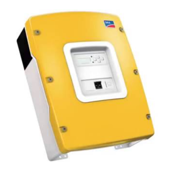
2 Sunny Island 4548-US / 6048-US SMA Solar Technology America LLC 2.2 At a Glance The following figure provides an overview of all control elements and connections of the Sunny Island: Position Description Display SI4548-6048-US-BE-en-21 Operating Manual... -
Page 23: Scope Of Delivery
SMA Solar Technology America LLC 2 Sunny Island 4548-US / 6048-US Position Description LEDs showing device operation Control buttons Slot for the SD memory card Opening for the additional connections area (insertion of the cables via conduits) Connection area for additional connections... - Page 24 2 Sunny Island 4548-US / 6048-US SMA Solar Technology America LLC Position Quantity Designation Sunny Island Wall mounting bracket Ventilation grid Battery temperature sensor Filler plug Counter nut for filler plug RJ45 cable, black Silicone tube Rubber plugs for feed-through of one cable...
-
Page 25: Required Tools And Materials
SMA Solar Technology America LLC 2 Sunny Island 4548-US / 6048-US Position Quantity Designation RS485 Piggy-Back (optional) RJ45 cable, white (optional) 2.4 Required Tools and Materials The following tools and materials are required in order to mount and install the... -
Page 26: Safety
• Ensure that the lithium-ion batteries are approved for use with the Sunny Island. The list of lithium-ion batteries approved by SMA for the Sunny Island is updated regularly (see the Technical Information "List of Approved Lithium-Ion Batteries" at www.SMA-America.com). -
Page 27: Important Notes Regarding Operation
Alterations to the product, e.g. modifications or conversions, are permitted only with the express written permission of SMA. Unauthorized alterations will void guarantee and warranty claims and usually void the operation permit. SMA shall not be held liable for any damage caused by such changes. - Page 28 • Verify that the particular lithium-ion battery type is approved for use with the SMA Sunny Island inverter (please see “List of Approved Lithium-Ion Batteries” under the Technical Information tab at www.SMA-America.com). • If manufacturer approved Sunny Island lithium-ion batteries are not available, you may use lead acid batteries.
-
Page 29: Potential Hazards
The Sunny Island has been designed for use at altitudes of up to 9,840 ft (3,000 m) above MSL. Please contact SMA before using the device at altitudes above 9,840 ft (3,000 m). A performance loss of 0.5% per 330 ft (100 m) is to be expected starting at an altitude of 6,560 ft (2,000 m) above MSL. - Page 30 3 Safety SMA Solar Technology America LLC Danger to life if the Sunny Island is used to supply energy to life-sustaining medical devices The Sunny Island was not developed to power life-sustaining medical devices. • Do not use the Sunny Island in systems in which a power outage might result in personal injury.
-
Page 31: Mounting
SMA Solar Technology America LLC 4 Mounting 4 Mounting 4.1 Selecting the Mounting Location Danger to life if installed in improper locations Death or serious burns. Despite careful construction, electrical devices can cause fires. • Do not mount the Sunny Island on flammable construction materials. - Page 32 4 Mounting SMA Solar Technology America LLC • Mount the Sunny Island in such a way that the display is at eye level in order to allow the operating state to be read at all times. • Mount vertically or tilted backwards by max. 45°.
-
Page 33: Mounting The Sunny Island With The Wall Mounting Bracket
SMA Solar Technology America LLC 4 Mounting 4.2 Mounting the Sunny Island with the Wall Mounting Bracket Operating Manual SI4548-6048-US-BE-en-21... -
Page 34: Mounting The Sunny Island On A Stone Wall
4 Mounting SMA Solar Technology America LLC 4.2.1 Mounting the Sunny Island on a Stone Wall Risk of injury due to the Sunny Island falling Physical injury (fractures or crushing) and damage to the Sunny Island. • Ensure that the wall can carry the weight of the Sunny Island. - Page 35 SMA Solar Technology America LLC 4 Mounting 5. Attach the Sunny Island to the wall mounting bracket. 6. Screw the Sunny Island to the wall mounting bracket on both sides using the screws (M6x10) provided. Tighten the screws clockwise. 7. Make sure that the screws are securely in place.
-
Page 36: Mounting The Sunny Island Using Wall Studs
4 Mounting SMA Solar Technology America LLC 4.2.2 Mounting the Sunny Island using Wall Studs Risk of injury due to the Sunny Island falling Physical injury (fractures or crushing) and damage to the Sunny Island. • Ensure that the wall can carry the weight of the Sunny Island. -
Page 37: Opening And Closing
SMA Solar Technology America LLC 5 Opening and Closing 5 Opening and Closing The enclosure of the Sunny Island has a removable lid. Remove the enclosure lid only when installing the device or for required maintenance or repair work. 5.1 Opening the Sunny Island 1. -
Page 38: Closing The Sunny Island
5 Opening and Closing SMA Solar Technology America LLC 5.2 Closing the Sunny Island Electric shock due to live enclosure lid Death or serious injuries. The grounding of the lid is ensured by the toothed washers. • Fasten the washers for all six screws with the toothing facing toward the enclosure lid. -
Page 39: Electrical Connection
SMA Solar Technology America LLC 6 Electrical Connection 6 Electrical Connection All cables are routed through the openings on the bottom side of the device (see next illustration) and connected to the appropriate terminals on the Sunny Island. Use conduits to install the cables on the DC side and on the AC side on the Sunny Island. Conduits ensure the dust-tight and water-tight mounting of a cable on the enclosure and also serve as a strain relief of the cable at the terminal. - Page 40 167°F (75°C). An overview of the different devices and their connection areas of the Sunny Island 4548-US / 6048-US can be found in section (see Section 2.2 "At a Glance", page 22). Detailed installation descriptions of the connections are provided in the following sections: •...
-
Page 41: Grounding
PE at the factory. However, since a connection between N and PE is required for correct operation, this must be done outside of the device. • Before commissioning, connect the Sunny Island 4548-US/6048-US and all other devices of the stand-alone grid to a grounded utility grid. - Page 42 ☑ The grounding conductor is connected. Calculating the cross-section of a grounding conductor SMA cannot state generally valid values for the cross-section of the grounding conductor required for the external grounding of the battery. The conductor dimensions depend on the type and size of the battery connected, the external fuse (DC side) and the material used for the grounding conductor.
-
Page 43: Dc Connection
SMA Solar Technology America LLC 6 Electrical Connection 6.2 DC Connection Function impairments of devices on the DC busbar The Sunny Island is not suitable for use with DC supply grids. Function impairment can occur on devices installed on the DC side of a Sunny Island with cables exceeding 98 ft (30 m) and with a flexible connection. - Page 44 • Verify that the particular lithium-ion battery type is approved for use with the SMA Sunny Island inverter (please see “List of Approved Lithium-Ion Batteries” under the Technical Information tab at www.SMA-America.com). • If manufacturer approved Sunny Island lithium-ion batteries are not available, you may use lead acid batteries.
-
Page 45: Cable Dimensioning
Do not lay the battery cable under plaster or in armored conduits. Choosing the wire size For cable lengths exceeding 33 ft (10 m), SMA recommends choosing wire sizes greater than ® those given by the National Electrical Code 310.15. -
Page 46: Cable Protection
6 Electrical Connection SMA Solar Technology America LLC 6.2.3 Cable Protection The DC circuit breaker in the Sunny Island can interrupt DC currents of up to 10 kA. In addition to the internal DC circuit breakers, install a separate, external fuse as close as possible to the battery. Install a fuse link for the fuse suitable for the maximum occurring DC currents. - Page 47 SMA Solar Technology America LLC 6 Electrical Connection Installing the DC Connection 1. Pull the positive DC cable through the conduit from the distribution board into the enclosure of the Sunny Island. 2. Pull the negative DC cable through the conduit from the distribution board into the enclosure of the Sunny Island.
-
Page 48: Ac Connection
6 Electrical Connection SMA Solar Technology America LLC 6.3 AC Connection 6.3.1 Cable Protection You must connect the Sunny Island via a sub-distribution to the stand-alone grid and any external source present. Fit the sub-distribution with appropriate circuit breakers and observe all locally applicable standards and directives. - Page 49 SMA Solar Technology America LLC 6 Electrical Connection Distributing loads and AC feed-in generators in multiple-phase systems Distribute the feed-in power and the consumed power of the loads and AC feed-in generators as equally as possible across all line conductors of the system.
-
Page 50: Ac2 (Generator/Grid)
6 Electrical Connection SMA Solar Technology America LLC 5. Insert the grounding conductor into the terminal labeled "AC1 Loads/Sunny Boys" and tighten the fastening screw with a torque of 22 in-lb (2.5 Nm). Use a torque wrench with flat-blade screwdriver bit SZS 1.0 x 6.5. - Page 51 SMA Solar Technology America LLC 6 Electrical Connection Three-phase system Always install the master on line conductor L1, slave 1 on L2 and slave 2 on L3. This installation has a right-hand rotating magnetic field. Additional fuses in the system...
-
Page 52: Additional Connections
6 Electrical Connection SMA Solar Technology America LLC 6. Insert N and L into the terminals labeled "AC2 Gen/Grid" and tighten the fastening screws with a torque of 22 in-lb (2.5 Nm). Use a torque wrench with flat-blade screwdriver bit SZS 1.0 x 6.5. -
Page 53: Connecting The Data Cable Of The Lithium-Ion Batteries
SMA Solar Technology America LLC 6 Electrical Connection 6.4.2 Connecting the Data Cable of the Lithium-Ion Batteries Requirements: The total length of the communication bus must not exceed 98 ft (30 m). Keep in mind that the communication bus possibly connects several nodes such as additional Sunny Island inverters. -
Page 54: Battery Current Sensor
6 Electrical Connection SMA Solar Technology America LLC Battery temperature sensor in a cluster A battery temperature sensor is provided with each Sunny Island. Only one battery temperature sensor is required for a cluster. Connect the temperature sensor to the master of the cluster. - Page 55 SMA Solar Technology America LLC 6 Electrical Connection Destruction of the battery due to the connection of additional DC devices If additional DC devices are installed in an off-grid system, the internal Sunny Island current measurement becomes inaccurate. The charge current can no longer be set exactly and as a result will destroy the battery.
-
Page 56: Communication For Multi-Device Connection
6 Electrical Connection SMA Solar Technology America LLC Installation notice The battery current sensor must be looped around the negative terminal of the battery. The terminal of the battery current sensor which is connected to the Sunny Island (1), must be connected to the terminal "BatCur+"... - Page 57 SMA Solar Technology America LLC 6 Electrical Connection Number of slaves Connection procedure 1 slave • Take the RJ45 cable coming from the master, insert it into the slave and plug it into the "ComSyncIn" pin connector. • Leave the terminator plugged into the "ComSyncOut" pin connector.
-
Page 58: Multifunction Relay 1 And 2
6 Electrical Connection SMA Solar Technology America LLC 6.4.6 Multifunction Relay 1 and 2 The Sunny Island offers you several options for the control of internal and external processes. Two multi-function relays are integrated into the Sunny Island to which you can assign functions using the parameters "241.01 Rly1Op"... - Page 59 SMA Solar Technology America LLC 6 Electrical Connection 4. Connect the insulated conductors to the supplied three-pole terminal. The pins have the following meaning: – NC: normally closed (when the Sunny Island is off, the relay is closed) – C: Contact (front contact) –...
- Page 60 6 Electrical Connection SMA Solar Technology America LLC Generator start The Sunny Island can control generators. The Sunny Island directly supports generators that can be started/stopped using a single contact. Default settings of the relays Relay 1 is preset to the "AutoGn" generator start function and relay 2 to the "AutoLodSoc" load shedding function.
-
Page 61: Batvtgout Power Supply
SMA Solar Technology America LLC 6 Electrical Connection 6.4.7 BatVtgOut Power Supply The battery voltage is conducted to the outside at these terminals. The battery voltage is fused at both poles by PTC resistors (max. 0.75 A). Depending on the internal temperature of the Sunny Island, the tripping threshold is over 0.75 A. -
Page 62: Interface For External Communication
☑ The DigIn digital input is connected. 6.5 Interface for External Communication You can connect SMA communication devices (e.g. Sunny WebBox) or a PC with the appropriate software to a communication interface. You will find a detailed wiring diagram in the communication device manual, the software or on the Internet at www.SMA-America.com. - Page 63 SMA Solar Technology America LLC 6 Electrical Connection Connecting the Interface for External Communication 1. Remove the right-hand plug from the cable support sleeve. Position Description Slot for communication interface Cable route Enclosure opening in the floor of the Sunny Island 2.
- Page 64 6 Electrical Connection SMA Solar Technology America LLC Sunny Boy/ RS485 – RJ45 pin connector - RJ45 plug color Sunny WebBox Signal allocation Sunny Island code B (Data–) green with white stripes 8. The RS485 data bus of the Sunny Island is terminated using a terminator. This terminator is already plugged into the "ComSmaOut"...
- Page 65 SMA Solar Technology America LLC 6 Electrical Connection Data Transmission Speed The Sunny Island can be operated at different data transfer rates to communicate with external devices. Set the parameter "250.06 ComBaud". Setting the baud rate If PV inverters are connected to the communication bus, then the baud rate must be set to 1,200 bps (default setting).
-
Page 66: Control Elements
7 Control Elements SMA Solar Technology America LLC 7 Control Elements In order to commission the Sunny Island, you should familiarize yourself with its operation beforehand. The individual control elements can be seen in the following figure. Position Description Display... -
Page 67: Display Messages
SMA Solar Technology America LLC 7 Control Elements 7.1 Display Messages The display of the Sunny Island has two lines, each with 16 characters. Meaning of the symbols Observe the information on the meaning of the individual symbols (see Section 10.6 "Display Messages (Overview)", page 89). -
Page 68: Dc Circuit Breaker
7 Control Elements SMA Solar Technology America LLC 7.2 DC Circuit Breaker The DC circuit breaker is used to switch on/off as well as to disconnect the Sunny Island on the DC side (see Section 9 "Switching On and Off", page 75). -
Page 69: Commissioning
Always save data Always use the SD memory card for storing data and events. In case of a failure SMA can thus help you quickly. • Always leave the SD memory card plugged in the Sunny Island. - Page 70 If you have a system with more than one Sunny Island, you must take the following measures: • Configure the Sunny Island with the latest firmware version as master or install the latest firmware version in the master (see www.SMA-America.com). The master updates the firmware of the slaves once the off-grid system is started.
- Page 71 SMA Solar Technology America LLC 8 Commissioning Systems with one Sunny Island If only one Sunny Island is used in the system, the device type is permanently set to "master" and is not displayed. – System configuration (see table for setting options)
- Page 72 8 Commissioning SMA Solar Technology America LLC Value in variable Explanation PvOnly Stand-alone grid, no utility grid, no generator Stand-alone grid with generator Grid Battery-backup grid GenGrid Battery-backup grid with generator GenGrid: – Maximum generator current (0 A to 224 A), default setting: "30 A"...
-
Page 73: Commissioning The Battery Current Sensor
SMA Solar Technology America LLC 8 Commissioning 8.3 Commissioning the battery current sensor In the event you have installed a battery current sensor in your system, you are required to synchronize the internal offset of the device. To do this, proceed as follows: 1. - Page 74 8 Commissioning SMA Solar Technology America LLC 8. Reconnect the conductors of the battery current sensor correctly as displayed in the graphic. Make sure the insulated conductors have the correct polarity. – BatCur+ to terminal 1 – BatCur– to terminal 2 9.
-
Page 75: Switching On And Off
SMA Solar Technology America LLC 9 Switching On and Off 9 Switching On and Off 9.1 Switching On Systems with several Sunny Island inverters Switch on the slaves before you switch on the master. To do this, proceed as follows. -
Page 76: Stopping The Sunny Island (Standby)
9 Switching On and Off SMA Solar Technology America LLC 4. Press and hold <ENTER>. ☑ Process bar is shown in the display. ☑ On a slave, the notification displayed here is shown until the master is started. 5. Press <ENTER> on the master. -
Page 77: Recommissioning After Automatic Shutdown
SMA Solar Technology America LLC 9 Switching On and Off 3. Disconnect the Sunny Island from the voltage sources (AC1 and AC2). Separate AC1 and AC2 and disconnect from voltage sources. ☑ If PV inverters are connected to AC1, they automatically switch off once they are no longer connected to the stand-alone grid. - Page 78 9 Switching On and Off SMA Solar Technology America LLC 4. Switch on the Sunny Island as described in section (see Section 9.1 "Switching On", page 75). Charging the batteries After recommissioning, it is important that the batteries are charged. If an autostart generator is present in the stand-alone grid, the Sunny Island will request the generator after a few minutes.
-
Page 79: Operation
SMA Solar Technology America LLC 10 Operation 10 Operation The main menu consists of a "Home Screen" and the other main menu entries, which split up into the different menu levels. Operating states, e.g. the current operating mode, power, etc. are displayed on the "Home Screen"... -
Page 80: Menu Structure
10 Operation SMA Solar Technology America LLC Exception: When starting the device for the first time, you must set the slave devices as slave in the QCG and everything else is performed from the master. Single Point of Operation Single Point of Operation also means that all log data of the master including the log data of the slaves are saved to the SD memory card on the master. - Page 81 SMA Solar Technology America LLC 10 Operation Overview of the Menu Structure: Operating Manual SI4548-6048-US-BE-en-21...
- Page 82 10 Operation SMA Solar Technology America LLC 100# Meters - Display values In this main menu, you will find the display values for the following devices of the off-grid system: • 110# Inverter Meters − Sunny Island • 120# Battery Meters − Battery •...
-
Page 83: Changing Parameters
SMA Solar Technology America LLC 10 Operation 600# Direct Access − Direct access to the parameters This is a main menu that gives you direct access to the settings and display values (see Section 10.3 "Direct Access - Direct Access to the Parameters", page 84). -
Page 84: Direct Access - Direct Access To The Parameters
10 Operation SMA Solar Technology America LLC 10.3 Direct Access - Direct Access to the Parameters The "600# Direct Access" menu gives you direct access to the selected parameter using the parameter name or number. Via the Select Name sub-menu, you have direct access to the following functions: •... - Page 85 SMA Solar Technology America LLC 10 Operation Bat1 (Battery values 1) Position Description Name of the compact meter Present battery state of charge (BatSoc) Estimated error of the state of charge (BatSocErr) Total battery current of the cluster (TotBatCur) Battery temperature (BatTmp)
- Page 86 10 Operation SMA Solar Technology America LLC Inv (AC Values of Inverter) Position Description Name of the compact meter Present voltage at the inverter (InvVtg) Present frequency at the inverter (InvFrq) Present active power of the inverter (InvPwrAt) Present reactive power at the inverter (InvPwrPt)
- Page 87 SMA Solar Technology America LLC 10 Operation Position Description Name of the compact meter Voltage of the external source (ExtVtg) Frequency of the external source (ExtFrq) Active power of the external source (ExtPwrAt) Reactive power of the external source (ExtPwrPt)
-
Page 88: Entering The Installer Password
10 Operation SMA Solar Technology America LLC 10.5 Entering the Installer Password Entering incorrect parameters endangers operational safety. Damage to the off-grid system and its components All parameter settings which could affect the operating safety of the off-grid system are protected by the installer password. -
Page 89: Display Messages (Overview)
SMA Solar Technology America LLC 10 Operation 8. Confirm the password by pressing <ENTER>. ☑ The installer password has been entered. Operating level [1] = the installer level is set. 9. Exit the menu by pressing the <ESC> key. Switching operating levels •... - Page 90 10 Operation SMA Solar Technology America LLC Position Description Relay 2 status Warning message (exclamation mark) The Sunny Island also shows the following values one after the other in the upper line of the "Home Screen" (parameter name and parameter value in 3-second intervals): •...
- Page 91 SMA Solar Technology America LLC 10 Operation Symbol Meaning Battery Load side (Loads/Sunny Boys) Utility pole The Sunny Island is working with grid limits. The Sunny Island is working with generator limits. The Sunny Island is configured as master. The Sunny Island is configured as slave 1.
-
Page 92: Parameter Display
10 Operation SMA Solar Technology America LLC Symbol Meaning "Start" request reason: The generator has been requested by the operator manually setting the generator request in the Sunny Island from "Auto" to "Start". The generator is then no longer automatically controlled or switched off by the Sunny Island. -
Page 93: Display Of Events
SMA Solar Technology America LLC 10 Operation Syntax for menus and parameters The syntax specified here for menus and parameters applies throughout the entire document. A menu is designated by the number of the menu, hash and the name of the menu (120# Battery Meters). -
Page 94: Data Storage On Sd Memory Card
Type of memory card SMA recommends the use of a Transcend SD memory card. If you use a memory card from another manufacturer, check whether the card is FAT-16 formatted. If necessary, format the card. Be aware that data stored on the card will be lost. - Page 95 SMA Solar Technology America LLC 11 Data Storage on SD Memory Card The files on the SD memory card have the following meanings: File name Meaning evthism.log (evthisN.log for SlaveN) Event history of the device, saved by means of parameter "550.03 CardFunc",...
-
Page 96: Inserting The Sd Memory Card
• External source • Loads Always save data Always use the SD memory card for storing data and events. In case of a failure SMA can thus help you quickly. 1. In the event of a fault contact the SMA Service Line. -
Page 97: Removing The Sd Memory Card
SMA Solar Technology America LLC 11 Data Storage on SD Memory Card Insert the SD memory card with the cut corner pointing down into the slot on the Sunny Island (see illustration). After inserting the SD memory card into the Sunny Island,... -
Page 98: Saving And Loading Parameters
11 Data Storage on SD Memory Card SMA Solar Technology America LLC 11.3 Saving and Loading Parameters You can configure and use various settings with various parameters, this means winter and summer. This parameter seta are known as Set 1 and Set 2. Using the parameter "550.01 ParaSto", you can save the current parameter settings and using the parameter "550.02 ParaLod", you can load the... -
Page 99: Status Messages
SMA Solar Technology America LLC 11 Data Storage on SD Memory Card 11.5 Status Messages Using the parameter 312.07 CardStt", you can query the status of your SD memory card: Display Description The SD memory card is deactivated. The SD memory card is activated. -
Page 100: Firmware Update
1. Create a backup copy of the existing parameter lists (see Section 11.3 "Saving and Loading Parameters", page 98). 2. Download the latest firmware version from the Internet at www.SMA-America.com. 3. Copy the "UPDATE.BIN" file to the SD memory card. 4. Set the master device to standby. - Page 101 SMA Solar Technology America LLC 11 Data Storage on SD Memory Card Starting QCG If you have carried out a firmware update in which the number before the dot in the firmware version has changed, it is advisable to start QCG and to perform all settings anew.
- Page 102 11 Data Storage on SD Memory Card SMA Solar Technology America LLC Display message Display from Explanation Master Master update part 2/ ⋮ Master The slave update starts. ⋮ Master The slave update is running. ⋮ Master The master update is completed.
-
Page 103: Additional Functions
SMA Solar Technology America LLC 12 Additional Functions 12 Additional Functions 12.1 Load Shedding If the loads connected to the Sunny Island consume more energy over a longer period of time than the generators connected produce, the batter can deeply discharge. The Sunny Island shuts down automatically if the state of charge of the battery is too low. - Page 104 12 Additional Functions SMA Solar Technology America LLC The figure shows an example of the settings if the step-by-step load shedding function at night is to be avoided as much as possible. From 6 a.m. to 10 p.m. the load shedding is activated for a state of charge (SOC) of 40%, at nighttime (from 10 p.m.
-
Page 105: Sleep Mode
The Sunny Island can be temporarily operated under overload conditions. and is able to supply short-circuit current. In the event of overload, the Sunny Island 4548-US supplies a power of 5,300 W for 30 minutes at 77°F (25°C) and the Sunny Island 6048-US a power of 7,000 W. Both Sunny Island inverters can deliver a power of 7,200 W for 5 minutes at 77°F (25°C). -
Page 106: Device Faults And Autostart
12 Additional Functions SMA Solar Technology America LLC Double-Split-Phase System In a double split-phase system, each line conductor must only be fitted with Sunny Island inverters of the same type (e.g. two Sunny Island 6048-US). 12.6 Device Faults and Autostart If a critical fault occurs, the Sunny Island automatically shuts down and displays the reason on the display. -
Page 107: Behavior In The Event Of A Failure In A Three-Phase System
SMA Solar Technology America LLC 12 Additional Functions 12.9 Behavior in the Event of a Failure in a Three-Phase System You can influence how the Sunny Island reacts to failures occurring in a three-phase system using the parameter "250.30 RnMod". The parameter is set to "RunAlways" at the factory. This means that the master ignores all errors at the slave devices. -
Page 108: Battery Management
C10/0.92 C100/1.15 C5/0.81 C1/0.57 SMA recommends the following minimum battery capacities: • Minimum battery capacity per Sunny Island inverter: – Sunny Island 4548-US: 190 Ah – Sunny Island 6048-US: 250 Ah • Minimum battery capacity per 1 kW output power of the PV system: 100 Ah (C20) The Sunny Island is designed and preset for a nominal battery voltage (parameter "221.03 BatVtgNom") of 48 V (24 cells for every 2 V) with lead-acid batteries (FLA and VRLA) and... -
Page 109: Battery Temperature
SMA Solar Technology America LLC 13 Battery Management 13.2 Battery Temperature The Sunny Island continuously monitors the battery temperature using the battery temperature sensor provided. At 9°F (5°C) below the maximum permissible temperature (parameter "221.04 BatTmpMax"), a warning message is displayed. If the maximum value for the battery temperature is exceeded, the Sunny Island switches off. - Page 110 13 Battery Management SMA Solar Technology America LLC Both the ampere-hour balancing method and the recalibration procedure which is performed via the voltage, automatically adjust to the connected battery over time (depends on the number of grid failures). The estimated state of charge error (display value "120.11 BatSocErr") will provide you with continuous information on the accuracy of the battery state of charge currently calculated.
-
Page 111: Charge Control
SMA Solar Technology America LLC 13 Battery Management 13.5 Charge Control The Sunny Island uses a three-level charge control, using the IUoU procedure. When operating with the utility grid, a fourth level, Silent Mode, is optionally available. The I stands for the constant current phase (I phase). In this phase, the charging is limited by the maximum defined battery current (parameter "222.01 BatChrgCurMax"), the nominal generator... - Page 112 13 Battery Management SMA Solar Technology America LLC Once this constant voltage phase is finished, the Sunny Island switches to float charge which again carries out constant voltage charging but at a greatly reduced charging voltage (parameter "222.10 ChrgVtgFlo"). The purpose of the float charge is to keep the battery in a fully charged state without causing premature aging through overcharging.
-
Page 113: Boost Charge
SMA Solar Technology America LLC 13 Battery Management 13.5.1 Boost Charge The boost charge is the most common charging process of the Sunny Island. The boost charge ensures a high generator workload through a high charging voltage over a short period of time. With liquid FLA lead-acid batteries, this charge process should be used for gassing and thus compensating the electrolytes. -
Page 114: Equalization Charge
13 Battery Management SMA Solar Technology America LLC 13.5.3 Equalization Charge A battery bank consists of many individual battery cells connected in series which all behave slightly different. Over time, this results in different charge levels in the individual cells. This can lead to premature failure, initially of individual cells, and finally to failure of the entire bank. -
Page 115: Battery-Preservation Mode
SMA Solar Technology America LLC 13 Battery Management "222.10 ChrgVtgFlo"). This ensures that the battery is always fully charged, even in silent mode. If a grid failure is detected during silent mode, the Sunny Island makes a stand-alone grid available within 10 ms to 30 ms. -
Page 116: Battery Diagnosis
13 Battery Management SMA Solar Technology America LLC At all three levels, the Sunny Island is stopped only if no battery charging current flows within ten minutes (limit: 3 A charging current). The limits for all three levels can be set independently from each other. This allows individual levels to be skipped. -
Page 117: Battery Lead Resistance
SMA Solar Technology America LLC 13 Battery Management 13.8 Battery Lead Resistance In menu "221# Battery Property", you can specify the battery lead resistance (BatWirRes). The resistance is the ohmic resistance from the battery to the input of the master device. The default value of the parameter "221.06 BatWirRes"... -
Page 118: Connecting External Sources
14 Connecting External Sources SMA Solar Technology America LLC 14 Connecting External Sources The Sunny Island supports the integration of external energy sources. Here, a distinction is made between the integration of a generator and the integration of the utility grid. - Page 119 SMA Solar Technology America LLC 14 Connecting External Sources Sunny Island Connected in Parallel to a 120 V Generator Sunny Island in the Split-Phase System connected to a 240 V Generator Generally, the internal transfer relays of the slaves close only if the internal relay of the master is closed.
-
Page 120: Generator Start Options
14 Connecting External Sources SMA Solar Technology America LLC Cable length and wire size Use the same cable length and the same wire size when installing the Sunny Island inverters with the generator. 14.1.2 Generator Start Options The Sunny Island supports the following options for starting the generator which can be set in standby mode with parameter "234.07 GnStrMod":... - Page 121 SMA Solar Technology America LLC 14 Connecting External Sources GenReq signal The GnReq signal (see Section 15 "Relays", page 140) is set for signaling the generator request and can thus be used as an alarm contact (in this case: a bulb). If no request is pending, the signal is reset.
-
Page 122: Generator Operation
14 Connecting External Sources SMA Solar Technology America LLC If the generator is started manually in this operating mode, the Sunny Island detects the running generator and connects it once the warm-up time has expired. If you stop the generator externally, this is detected, the generator disconnected and the stand-alone grid is still supplied. -
Page 123: Automatic Generator Operation
SMA Solar Technology America LLC 14 Connecting External Sources Run1h: Operation for one hour. Once the lockout time has expired, the transition back into automatic mode follows. An equalization charge can be manually started using the parameter "520.01 ChrgSelMan". This sets the battery management (see Section 13 "Battery Management", page 108) in the equalization... - Page 124 14 Connecting External Sources SMA Solar Technology America LLC Charge State Dependent Start The Sunny Island changes to the operating mode "Stop/Lock" when stopped manually during automatic operation. • Manual inputs on the Sunny Island have a higher priority than automatic operation.
- Page 125 SMA Solar Technology America LLC 14 Connecting External Sources Reaching the float charging process If the float charging process (see Section 13.5 "Charge Control", page 111) is activated before the cutoff limit (GnSocTm1Stp or GnSocTm2Stp) is reached, the generator request is disabled again.
-
Page 126: Limits And Power Control
14 Connecting External Sources SMA Solar Technology America LLC Generator Interface "234.07 GnSrtMod" = Autostart; Request Via Sunny Island Generator started by Sunny Island Generator start Beginning of warm-up time Warm-up time has expired Generator is connected Current limit Minimum running time is expired... -
Page 127: Run Times
SMA Solar Technology America LLC 14 Connecting External Sources The Sunny Island charges the generator at each line conductor with the current defined in the parameter "234.03 GnCurNom" as a maximum. The power that is not directly used by the loads flows into the battery for charging. -
Page 128: Operation Together With Pv Inverters And Wind Power Inverters
14 Connecting External Sources SMA Solar Technology America LLC This state lasts for the time period set at "234.11 GnErrStpTm". Once this time has expired, the generator is ready for another attempt. Autostart meter The recording of autostarts is only reset after the generator has been successfully connected and the minimum run time has expired or when the locked error state (Fail Lock) is disabled. -
Page 129: Stopping The Generator
SMA Solar Technology America LLC 14 Connecting External Sources 14.1.9 Stopping the Generator If the generator was started via the Sunny Island (automatically or manually), it can be manually stopped at any time using the parameter "540.01 GnManStr". This disconnects the generator (the minimum run time is not taken into account here) and the power-down time (Cool) is skipped. -
Page 130: Utility Grid
14 Connecting External Sources SMA Solar Technology America LLC Reverse power Observe the reverse power which the Sunny Island can generate. The generator must provide this protection; observe the information of the generator manufacturers. Generator Failure If a generator failure is detected (failure on the master phase), the generator is disconnected immediately and a stop signal occurs on generator. -
Page 131: Starting The Sunny Island
This function can be realized with the Sunny Island inverters in combination with the compatible PV inverters. You will find the list with compatible PV inverters in the download are at www.SMA-America.com in the Technical Information "PV Inverters: Use of PV Inverters in Off-Grid Systems and Battery-Backup Systems North America and South America". -
Page 132: Grid Reconnection
14 Connecting External Sources SMA Solar Technology America LLC 14.2.5 Grid Reconnection In stand-alone mode, the Sunny Island constantly checks whether the grid has been reconnected (see above). The following conditions have to be fulfilled to guarantee that the Sunny Island synchronizes with the utility grid and connects to the utility grid: •... - Page 133 SMA Solar Technology America LLC 14 Connecting External Sources The Sunny Island connects to the utility grid when the state of charge of its batteries lies within the limits determined by the following parameters: • "233.01 GdSocTm1Str" to "233.02 GdSocTm1Stp"...
- Page 134 14 Connecting External Sources SMA Solar Technology America LLC Silent Mode In order to save energy, the silent mode can be activated using the parameter "224.01 SilentEna" set to "Enable" (default disable). In this case, the Sunny Island is set to standby mode if the charge has been completed and the battery has been in float charge for some time (see Section 13.5.5 "Silent...
-
Page 135: Grid Failure
SMA Solar Technology America LLC 14 Connecting External Sources 14.2.7 Grid Failure A grid fault is characterized by the voltage or frequency being outside of the permissible limits (see Section 14.2.5 "Grid Reconnection", page 132) or the utility grid being disconnected. In this case, the time limits are relevant: smaller deviations are permitted for longer than large deviations (see Section 14.2.1 "Limits of the Voltage Range and Frequency Range", page 130). -
Page 136: Limitations And Power Control
14 Connecting External Sources SMA Solar Technology America LLC Failure of a Grid Line Conductor The failure of a line conductor (e.g. broken fuse) on a slave device is treated as a line conductor failure. The slave device then disconnects this line conductor. If the line conductor is detected as being available again, it is reconnected. -
Page 137: Generator And Utility Grid
SMA Solar Technology America LLC 14 Connecting External Sources Energy of the PV inverters or wind power inverters not being consumed in the off-grid system, is fed-in by the Sunny Island via the internal transfer relay into the utility grid. The Sunny Island prevents an overload of the internal transfer relay. - Page 138 • If a manual switch is installed, leave the switch in the OFF position for at least five seconds before switching to the new position. • If no switch is installed, install a switch (see Technical Information „Sunny Island 4548-US / 5048-US / 6048-US: Grid Backup with Generator“ at www.SMA-America.com).
- Page 139 SMA Solar Technology America LLC 14 Connecting External Sources In order to switch the signal circuit via the DigIn input, a single pole break contact or a single pole auxiliary relay with a 120 V coil is necessary. If there is no auxiliary relay present in the ATS, you must install an external contactor with a 120 V or 240 V coil.
-
Page 140: Relays
15 Relays SMA Solar Technology America LLC 15 Relays The Sunny Island offers you several options for the control of internal and external processes. Two multi-function relays are integrated into the device to which you can assign functions using the parameters "241.01 Rly1Op"... - Page 141 SMA Solar Technology America LLC 15 Relays Function/ Meaning Function description Setting ExtVfOk External voltage and External voltage and frequency are within the valid frequency OK range for connection. GdOn Utility grid Relay switching when utility grid is available and connected.
- Page 142 15 Relays SMA Solar Technology America LLC Function/ Meaning Function description Setting MccAutoLod Multicluster auto Automatic disconnection of the loads via an Loadshedding extension cluster in the Multicluster system "MccAutoLod" is the request from the master of the main cluster that is transmitted to a master of an extension cluster in order to use its relay for the automatic disconnection of the loads.
-
Page 143: Multicluster Operation
For increased output, up to four Sunny Island clusters can be interconnected to form a Multicluster system. A Multicluster Box for Sunny Island 4548-US / 5048-US / 6048-US (MCB-12U) is required for such systems. Within each cluster, a communication interface connects the master to the slaves. - Page 144 16 Multicluster Operation SMA Solar Technology America LLC RJ45 cable The RJ45 data cable is a standard Cat5e-FTP cable (simple shielding), with gold contacts. Each Multicluster Piggy-Back (MC-PB) is delivered with one yellow and one gray RJ45 data cable and two plugs (terminators).
-
Page 145: Commissioning The Multicluster System
SMA Solar Technology America LLC 16 Multicluster Operation 16.2 Commissioning the Multicluster System Possible load shedding during initial start-up of a multicluster system Unwanted load shedding can occur during the initial start-up of a multicluster system. The possible causes of this can be a too-low state of charge of the battery or a still too inaccurate charge level calculation in the Sunny Island. -
Page 146: Switching A Multicluster System On And Off
16 Multicluster Operation SMA Solar Technology America LLC 16.3 Switching a Multicluster System On and Off 16.3.1 Switching On/Starting Switching on a Multicluster system can only take place at the master of the main cluster. The extension clusters will be started automatically after starting the main cluster. To do this, the DC circuit breakers of all Sunny Island inverters in the extension cluster must be set to "ON". -
Page 147: Load Shedding In A Multicluster System
SMA Solar Technology America LLC 16 Multicluster Operation 16.3.3 Load Shedding in a Multicluster System The load-shedding contactor in the Multicluster Box is controlled depending on the state of charge of the batteries. Significance of the SOC thresholds: When the state of charge of a battery reaches the lower SOC threshold, the load contactor is opened. -
Page 148: Testing Multicluster Communication
16 Multicluster Operation SMA Solar Technology America LLC Nominal capacity of the battery storage systems Ideally, the various battery banks should all have the same nominal capacity. If the nominal capacity varies by up to 30%, a similar average state of charge is ensured via the equalization function. -
Page 149: Error Handling In A Multicluster System
SMA Solar Technology America LLC 16 Multicluster Operation 16.9 Error Handling in a Multicluster System For Multicluster system operation, the entire main cluster is always required. If a device in the main cluster fails (master and/or slave), this causes the main cluster to stop. -
Page 150: Pv Inverters
Danger to life due to high voltages in the Sunny Island system. Death or serious injury possible due to electric shock • Ensure that the entire connection area of the Sunny Island 4548-US / 6048-US is voltage-free before installing the Sunny Boy inverter. -
Page 151: Setting The Off-Grid Parameters
• Install a communication product corresponding to the type of communication and the PV inverter used. • Apply for an SMA Grid Guard code to change grid-relevant parameters (for an application for the SMA Grid Guard code, see the Certificate "Application for SMA Grid Guard Code"... -
Page 152: Parameter Settings Of The Pv Inverters
17 PV Inverters SMA Solar Technology America LLC PV Inverters with BLUETOOTH You can configure PV inverters with BLUETOOTH using the following communication products: • Sunny Explorer • Sunny WebBox mit BLUETOOTH Wireless Technology 17.4 Parameter Settings of the PV Inverters 17.4.1 Configuration of the PV Inverters in Battery-Backup Systems... -
Page 153: Configuration Of Pv Inverters In Off-Grid Systems
SMA Solar Technology America LLC 17 PV Inverters 17.4.2 Configuration of PV Inverters in Off-Grid Systems The country data set must be set to stand-alone mode in off-grid systems. You can order PV inverters configured for stand-alone mode or you can configure existing PV inverters for stand-alone mode (see Section 17.3 "Configuration of the PV Inverters with a Communication... -
Page 154: Frequency-Shift Power Control (Fspc)
(solar) power available from the PV array exceeds the power required by the connected loads. To prevent the excess energy from overcharging the battery, the Sunny Island 4548-US / 6048-US recognizes this situation and changes the frequency at the AC output. This frequency adjustment is analyzed by the Sunny Boy. - Page 155 SMA Solar Technology America LLC 17 PV Inverters The different settings have the following meanings: • f refers to the base frequency of the stand-alone grid created by the Sunny Island. • f Delta– and f Delta+ refer to the maximum range in which the Sunny Boy is active, based on, e.g.
-
Page 156: Maintenance And Care
18 Maintenance and Care SMA Solar Technology America LLC 18 Maintenance and Care The Sunny Island has been constructed for low maintenance. Thus, the necessary work is limited to only a few points. 18.1 Enclosure Check that the Sunny Island enclosure is mechanically sound. If damage (e.g. cracks, holes, missing covers) endangers the operating safety, the Sunny Island must be deactivated immediately. -
Page 157: Battery
Dispose of the Sunny Island at the end of its electrical endurance in accordance with the disposal regulations for electronic waste which apply at the installation site at that time. Alternatively, send the devices back to SMA with shipping paid by sender, and labeled with the information "FOR DISPOSAL" (see Section 25 "Contact", page 242). -
Page 158: Parameter Lists
19 Parameter Lists SMA Solar Technology America LLC 19 Parameter Lists Only parameters in the menu branches "200 Settings" and "500 Operation" can be changed. All other values are only shown on the display of the SI 4548-US-10 / 6048-US-10. All menu items that can only be changed by the installer using a password are shaded in gray in the following tables. - Page 159 SMA Solar Technology America LLC 19 Parameter Lists No. Name Description Value clear Explanation text (No.) InvFrq Frequency of the Sunny Island in Hz InvPwrRt Reactive power of the Sunny Island in kVAr Rly1Stt State of relay 1 Relay open...
- Page 160 19 Parameter Lists SMA Solar Technology America LLC 114# Inverter Slave2 Meters No. Name Description Value clear Explanation text (No.) InvOpSttSlv2 Operating state of Standby (2) Standby slave 2 Run (3) Operation EmCharge (4) Emergency charge mode Error (5) Error...
-
Page 161: Battery Meters (120#)
SMA Solar Technology America LLC 19 Parameter Lists No. Name Description Value clear Explanation text (No.) InvCurSlv3 Current of slave 3 in A InvPwrRtSlv3 Reactive power of slave 3 in kVAr Rly1SttSlv3 State of relay 1 on Relay open slave 3... -
Page 162: External Meters (130#)
19 Parameter Lists SMA Solar Technology America LLC No. Name Description Value clear Explanation text (No.) RmgTmEqu Remaining time until next equalization charge in days AptPhs Status of the Off (1) Absorption phase not active absorption phase On (2) Absorption phase is active... - Page 163 SMA Solar Technology America LLC 19 Parameter Lists 133# Generator State No. Name Description Value clear Explanation text (No.) GnDmdSrc Source for generator None (1) No request request Bat (2) Dependent on battery state of charge Lod (3) Load-dependent Tim (4)
- Page 164 19 Parameter Lists SMA Solar Technology America LLC 134# Device Meters No. Name Description ExtPwrAt Active power of the external source in kW ExtVtg Voltage of the external source in V ExtCur Current of the external source in A ExtFrq...
-
Page 165: Charge Controller (140#)(Not Ul-Certified)
SMA Solar Technology America LLC 19 Parameter Lists 138# Chp Meters (Combined Heat and Power) No. Name Description Value Explanation ChpStt State of CHP plant Idle Operation Lock Locked after operation ChpPwrAt Power of the CHP plant ChpRmgTm Remaining time of the... - Page 166 19 Parameter Lists SMA Solar Technology America LLC 142# SIC50 1 No. Name Description Sic1EgyCntIn Energy of the first Sunny Island Charger in kWh Sic1TdyEgyCntI Daily yield of the first Sunny Island Charger in kWh Sic1PvPwr PV power of the first Sunny Island Charger in W...
-
Page 167: Adjustable Parameters
SMA Solar Technology America LLC 19 Parameter Lists No. Name Description Sic3SWVers Software version of the third Sunny Island Charger 145# SIC50 4 No. Name Description Sic4EgyCntIn Energy of the fourth Sunny Island Charger in kWh Sic4TdyEgyCntI Daily yield of the fourth Sunny Island Charger in kWh... -
Page 168: Battery Settings (220#)
19 Parameter Lists SMA Solar Technology America LLC 19.2.2 Battery Settings (220#) 221# Battery Property No. Name Description Value Explanation Default value BatTyp Battery type VRLA Lead-acid battery VRLA with immobilized electrolyte in gel or AGM (Absorbent Glass Mat Separator) Valve-regulated lead–acid battery... - Page 169 SMA Solar Technology America LLC 19 Parameter Lists #222 Battery Charge Mode No. Name Description Value Explanation Default value BatChrgCurMax Charging current 10 A to 1,200 A 61 A of the battery AptTmBoost Absorption time for 1 min to 600 min...
- Page 170 19 Parameter Lists SMA Solar Technology America LLC No. Name Description Value Explanation Default value BatTmpCps Battery 0 mV/C° to VRLA 4.0 mV/ temperature °C 10 mV /°C compensation 4.0 mV/ °C NiCd 0 mV/ °C AutoEquChrgEn Automatic Disable Disable...
- Page 171 SMA Solar Technology America LLC 19 Parameter Lists #224 Battery Silent Mode No. Name Description Value Explanation Default value SilentEna Silent mode on utility Disable Disable Disable grid Enable Enable SilentTmFlo Maximum time for float 1 h to 48 h...
-
Page 172: External Settings (230#)
19 Parameter Lists SMA Solar Technology America LLC 226# BMS Mode Basic / Off No. Name Description Value Explanation Default value BatChrgVtgMan Manual setpoint of the 41.0 V to 63.0 V 54.0 V battery charging voltage with disabled battery management... - Page 173 SMA Solar Technology America LLC 19 Parameter Lists 232# Grid Control No. Name Description Value Explanation Default value GdVtgMin Minimum grid voltage 105.6 V GdVtgMax Maximum grid voltage 132 V GdCurNom Nominal grid current 30 A GdFrqNom Nominal grid 60 Hz...
- Page 174 19 Parameter Lists SMA Solar Technology America LLC No. Name Description Value Explanation Default value GdPwrEna Activate the grid Disable Disable Disable request based on Enable Enable power 233# Grid Start No. Name Description Value Explanation Default value GdSocTm1Str SOC limit for switching...
- Page 175 SMA Solar Technology America LLC 19 Parameter Lists 234# Generator Control No. Name Description Value Explanation Default value GnVtgMin Minimum generator 80 V voltage GnVtgMax Maximum generator 150 V voltage GnCurNom Nominal generator 30 A current GnFrqNom Nominal generator 60 Hz...
- Page 176 19 Parameter Lists SMA Solar Technology America LLC No. Name Description Value Explanation Default value GnAlSns AI sensitivity Normal Medium Medium Normal Normal High High GnCurCtlMod Enable I-Loop in Droop (1) Standard Droop (1) generator mode generator operation without I - Loop...
- Page 177 SMA Solar Technology America LLC 19 Parameter Lists No. Name Description Value Explanation Default value GnTm2Str Time 2 for generator request in hours, minutes and seconds Start: time 2, end: time GnPwrEna Generator request Disable based on power Enable GnPwrStr...
- Page 178 19 Parameter Lists SMA Solar Technology America LLC No. Name Description Value Explanation Default value GnStrChrgMod Generator start for Both charge type Full Full charge Equal Equalization charge Both Full and equalization charge GnStrDigIn Generator start upon Disable Disable Disable...
- Page 179 SMA Solar Technology America LLC 19 Parameter Lists 236# CHP Control (Combined Heat and Power) No. Name Description Value Explanation Default value ChpOpTmMin Minimum run time of 60 min CHP plant ChpStpTmMin Minimum stop time of 10 min CHP plant...
- Page 180 19 Parameter Lists SMA Solar Technology America LLC No. Name Description Value Explanation Default value ChpPwrEna Activate CHP plant Disable Disable Enable request based on Enable Enable power ChpPwrStr CHP plant request, 4 kW connection power limit ChpPwrStrDly Time delay for power...
-
Page 181: Relay Settings (240#)
SMA Solar Technology America LLC 19 Parameter Lists 19.2.4 Relay Settings (240#) 241# Relay General No. Name Description Value Explanation Default value Rly1Op Function relay 1 AutoGn AutoGn Generator request AutoLodExt External loadshedding AutoLod1Soc SOC1 Loadshedding AutoLod2Soc SOC2 Loadshedding Tmr1... - Page 182 19 Parameter Lists SMA Solar Technology America LLC No. Name Description Value Explanation Default value Rly2Op Function relay 2 AutoLod AutoGn Generator request AutoLodExt External loadshedding AutoLod1Soc SOC1 Loadshedding AutoLod2Soc SOC2 Loadshedding Tmr1 Timer 1 Tmr2 Timer 2 AptPhs Absorption phase...
- Page 183 SMA Solar Technology America LLC 19 Parameter Lists No. Name Description Value Explanation Default value ExtPwrDerMinT Minimum time of 0 min to 10 min external power 600 min reduction ExtPwrDerDltVtg Differential voltage 0 V to 0.4 V 0.15 V of external power...
- Page 184 19 Parameter Lists SMA Solar Technology America LLC No. Name Description Value Explanation Default value Lod2Tm1Str Time 1 for Loadshed 2 in hours, minutes and seconds Start: time 1, end: time Lod2Tm2Str Time 2 for Loadshed 2 in hours, minutes and...
- Page 185 SMA Solar Technology America LLC 19 Parameter Lists 244# Relay Slave1 No. Name Description Value Explanation Default value Rly1OpSlv1 Function of relay 1 on slave 1 AutoGn Generator request AutoLodExt External loadshedding AutoLod1Soc SOC1 Loadshedding AutoLod2Soc SOC2 Loadshedding Tmr1 Timer 1...
- Page 186 19 Parameter Lists SMA Solar Technology America LLC No. Name Description Value Explanation Default value Rly2OpSlv1 Function of relay 2 on slave 1 AutoGn Generator request AutoLodExt External loadshedding AutoLod1Soc SOC1 Loadshedding AutoLod2Soc SOC2 Loadshedding Tmr1 Timer 1 Tmr2 Timer 2...
- Page 187 SMA Solar Technology America LLC 19 Parameter Lists 245# Relay Slave2 No. Name Description Value Explanation Default value Rly1OpSlv2 Function of relay 1 on slave 2 AutoGn Generator request AutoLodExt External loadshedding AutoLod1Soc SOC1 Loadshedding AutoLod2Soc SOC2 Loadshedding Tmr1 Timer 1...
- Page 188 19 Parameter Lists SMA Solar Technology America LLC No. Name Description Value Explanation Default value Rly2OpSlv2 Function of relay 2 on slave 2 AutoGn Generator request AutoLodExt External loadshedding AutoLod1Soc SOC1 Loadshedding AutoLod2Soc SOC2 Loadshedding Tmr1 Timer 1 Tmr2 Timer 2...
- Page 189 SMA Solar Technology America LLC 19 Parameter Lists 246# Relay Slave3 No. Name Description Value Explanation Default value Rly1OpSlv3 Function of relay 1 on slave 3 AutoGn Generator request AutoLodExt External loadshedding AutoLod1Soc SOC1 Loadshedding AutoLod2Soc SOC2 Loadshedding Tmr1 Timer 1...
- Page 190 19 Parameter Lists SMA Solar Technology America LLC No. Name Description Value Explanation Default value Rly2OpSlv3 Function of relay 2 on slave 3 AutoGn Generator request AutoLodExt External loadshedding AutoLod1Soc SOC1 Loadshedding AutoLod2Soc SOC2 Loadshedding Tmr1 Timer 1 Tmr2 Timer 2...
-
Page 191: System Settings (250#)
SMA Solar Technology America LLC 19 Parameter Lists 19.2.5 System Settings (250#) No. Name Description Value Explanation Default value AutoStr Autostart If the value 0 has been set, this means that the autostart is deactivated. Date MM/DD/YYYY 99.99.9999 Time in hours,... - Page 192 19 Parameter Lists SMA Solar Technology America LLC No. Name Description Value Explanation Default value ComBaud Baud rate 1,200 1,200 4,800 9,600 19,200 ComAdr Address for communication SleepEna Sleep mode Disable Disable Enable Enable Enable AfraEna Tertiary control Disable Disable...
-
Page 193: Password Setting (280#)
SMA Solar Technology America LLC 19 Parameter Lists No. Name Description Value Explanation Default value ChrgCtlOp Typ of DC Auto Automatic Auto charging device DCOnly Battery charger only Sunny Island Charg RnMod "Run Mode" RunAlways Always available RunAlways Behavior under... - Page 194 19 Parameter Lists SMA Solar Technology America LLC No. Name Description Value clear text Explanation Default (No.) value OnTmh Operating hours of the Sunny Island in hours ClstCfgAt Set cluster configuration The value is based on the setting in OpStt...
- Page 195 SMA Solar Technology America LLC 19 Parameter Lists 313# Inverter Slave1 Diagnosis No. Name Description Value Explanation FwVerSlv1 Firmware version of slave 1 SNSlv1 Serial number of slave 1 OnTmhSlv1 Operating hours of slave 1 in hours PhSlv1 Phase position of...
-
Page 196: Battery Diagnosis (320#)
19 Parameter Lists SMA Solar Technology America LLC No. Name Description Value Explanation FwVer2Slv2 DSP firmware version of slave 2 FwVer3Slv2 OCU boot loader of slave 2 FwVer4Slv2 DSP boot loader of slave 2 315# Inverter Slave3 Diagnosis No. Name... - Page 197 SMA Solar Technology America LLC 19 Parameter Lists No. Name Description Value Explanation Default value StatTm Run time of statistics counter in days ChrgFact Charging factor 1.00 BatEgyCntIn Energy meter for battery charging in kWh BatEgyCntOut Energy meter for battery discharge in...
- Page 198 19 Parameter Lists SMA Solar Technology America LLC No. Name Description Value Explanation Default value BatCurPkIn Maximum battery current in the charging direction (in A) BatCurPkOut Maximum battery current in discharging direction (in A) SocHgm100 Frequency scale of state of charge in percent, 100% >...
- Page 199 SMA Solar Technology America LLC 19 Parameter Lists No. Name Description Value Explanation Default value SocHgm020 Frequency scale of state of charge in percent, 20% > SOC >= 10% SocHgm010 Frequency scale of state of charge in percent, 10% > SOC >= 0%...
-
Page 200: External Diagnosis (330#)
19 Parameter Lists SMA Solar Technology America LLC 19.3.3 External Diagnosis (330#) 331# Grid Diagnosis No. Name Description GdEgyCntIn Energy meter for grid feed-in in kWh GdEgyCntOut Energy meter for power taken from the grid in kWh GdEgyTmh Run time of energy meter for utility grid in hours... - Page 201 SMA Solar Technology America LLC 19 Parameter Lists No. Name Description Value Explanation Default value InvTmOpStrDt Start date for 2006-0 time-controlled inverter 1-01 operation InvTmOpStrTm Start time for Value can be set time-controlled inverter freely operation in hours, minutes and seconds...
- Page 202 19 Parameter Lists SMA Solar Technology America LLC No. Name Description Value Explanation Default value FrcClstUpd Manual update of the UpdateClst Cluster update cluster (OCU & DSP) UpdateClstBFR Cluster update (OCU) UpdateClstDSP Cluster update (DSP) 520# Operation Battery No. Name...
-
Page 203: Direct Access To The Parameters
SMA Solar Technology America LLC 19 Parameter Lists No. Name Description Value Explanation Default value CardFunc Functions of the SD ForcedWrite Forced write memory card StoEvtHis Save event memory StoFailHis Save error log StoHis Storing event and fault memory DatLogEna... -
Page 204: Troubleshooting
20 Troubleshooting SMA Solar Technology America LLC 20 Troubleshooting In general, the Sunny Island distinguishes between events and errors. • Events describe state changes or transient states (e.g. generator connection). • Errors describe states that are not permitted or are only permitted up to a certain rate. This includes warnings, distrubances and errors. -
Page 205: Handling Of Pending Errors During The Booting Procedure
SMA Solar Technology America LLC 20 Troubleshooting No comparison between master and slave The error and event memory are not compared between the master and slaves. The errors of the slave device are acknowledged when the Sunny Island system is restarted. -
Page 206: Category Bat
20 Troubleshooting SMA Solar Technology America LLC Display no. Description E107 Sleep mode (slave in single-phase systems) E108 Silent mode on utility grid E110 Shutdown due to error E115 Emergency charge E118 Automatic start E119 Manual start (transition from standby mode to operation) -
Page 207: Category Grd
SMA Solar Technology America LLC 20 Troubleshooting Display no. Description E404 Manual generator stop E405 Manual error acknowledgment of generator error E406 Source of generator request E407 Current-regulated generator operation initiated E408 Current-controlled generator operation stopped 20.6.4 Category GRD Display no. -
Page 208: Category Sys
20 Troubleshooting SMA Solar Technology America LLC Display no. Description E614 Transfer relay on slave 2 closed E615 Transfer relay on slave 3 open E616 Transfer relay on slave 3 closed E617 Relay 2 open E618 Relay 2 closed E619... -
Page 209: Failure Categories
SMA Solar Technology America LLC 20 Troubleshooting Display no. Description E853 Sunny Island Charger #3 detected E854 Sunny Island Charger #4 detected E901 SOC recalibration started E902 SOC recalibration stopped E903 Derating started E904 Derating stopped E905 Preventive self-disconnection to protect the battery from deep discharge 20.7 Failure Categories... -
Page 210: Category Inv
20 Troubleshooting SMA Solar Technology America LLC 20.8.1 Category INV Display no. Level Description F109 Transformer overtemperature W110 Overtemperature transformer slave 1 W111 Overtemperature transformer slave 2 W112 Overtemperature transformer slave 3 F113 Overtemperature heat sink W114 Overtemperature heat sink slave 1... -
Page 211: Category Bat
SMA Solar Technology America LLC 20 Troubleshooting 20.8.2 Category BAT Display no. Level Description F201 Measuring range of battery voltage exceeded W202 Measuring range of battery voltage exceeded on slave 1 W203 Measuring range of battery voltage exceeded on slave 2... - Page 212 20 Troubleshooting SMA Solar Technology America LLC Display no. Level Description W320 Disconnection from utility grid/generator due to excessive external voltage slave 1 W321 Disconnection from utility grid/generator due to excessive external voltage slave 2 W322 Disconnection from utility grid/generator due to excessive external...
- Page 213 SMA Solar Technology America LLC 20 Troubleshooting Display no. Level Description W340 Disconnection from utility grid/generator due to voltage increase protection slave 1 W341 Disconnection from utility grid/generator due to voltage increase protection slave 2 W342 Disconnection from utility grid/generator due to voltage increase...
-
Page 214: Category Gen
20 Troubleshooting SMA Solar Technology America LLC 20.8.4 Category GEN Display no. Level Description W401 Reverse power protection (generator) W402 Generator management switches into the locked error status (Fail-Lock) 20.8.5 Category GRD Display no. Level Description W501 Grid reverse current prevented (quick grid disconnection) - Page 215 SMA Solar Technology America LLC 20 Troubleshooting Display no. Level Description F706 Watchdog meter elapsed (watchdog tripped several times in succession) W707 Watchdog meter on slave 1 elapsed (watchdog tripped several times in succession) W708 Watchdog meter on slave 2 elapsed (watchdog tripped several times...
- Page 216 20 Troubleshooting SMA Solar Technology America LLC Display no. Level Description W744 Internal CAN communication of slave 1 is interrupted W745 Internal CAN communication of slave 2 is interrupted W746 Internal CAN communication of slave 3 is interrupted W747 Short circuit or cable break on transformer temperature sensor slave 1...
-
Page 217: Aux Category
SMA Solar Technology America LLC 20 Troubleshooting 20.8.8 AUX Category Display no. Level Description F801 Plausibility check of contactors in a Multicluster Box failed W804 Grid operation not possible W805 Generator operation not possible F806 Multicluster Box settings do not match software settings. -
Page 218: Category Sys
20 Troubleshooting SMA Solar Technology America LLC Display no. Level Description W874 No PV voltage or short circuit on Sunny Island Charger 3 W875 Sensor error (or undertemperature) on Sunny Island Charger 3 W876 Overtemperature Sunny Island Charger 3 W877... -
Page 219: Troubleshooting
SMA Solar Technology America LLC 20 Troubleshooting Display no. Level Description F932 Error message via SiCom: Different state of charge of the battery cells F935 Error message via SiCom: Error in the generator W936 Warning via SiCom: General W937 Warning via SiCom: Battery overvoltage... - Page 220 • The Sunny Boy inverter is controlled via the frequency (see Section 17.5 "Frequency-Shift Power Control (FSPC)", page 154). • The automatic frequency synchronization function of the Sunny Island 4548-US / 6048-US is activated (see Section 12.7 "Automatic Frequency Synchronization", page 106). • Power fluctuations cause frequency deviations.
- Page 221 SMA Solar Technology America LLC 20 Troubleshooting What can I do when the battery cell of a lead-acid battery can no longer be used? • Remove the cell that can no longer be used from your battery bank. Start the Sunny Island and change the battery voltage in the QCG under "New Battery".
- Page 222 20 Troubleshooting SMA Solar Technology America LLC How is it possible to change between wintertime and summertime operation e.g. for alpine huts? • Save two different parameter sets on the SD memory card and activate them via parameter "550.02 ParaLod" (see Section 11.3 "Saving and Loading Parameters", page 98).
-
Page 223: Procedure During Emergency Charge Mode
SMA Solar Technology America LLC 20 Troubleshooting Why is it that high outputs are being transferred back and forth between the clusters in the cluster network? • The nominal frequencies and voltages are defined differently. Correct this by means of the appropriate parameters. - Page 224 20 Troubleshooting SMA Solar Technology America LLC 2. Confirm the following view with <ENTER>. 3. Set the maximum external current, e.g. that of the generator. 4. Confirm the set value with <ENTER>. 5. Use the down arrow key. ☑ The display on the right appears.
- Page 225 SMA Solar Technology America LLC 20 Troubleshooting In emergency charge mode, process values are shown in the display. Parameters cannot be changed during the charging process. If the Sunny Island is restarted, the settings that were saved before the ECM are loaded.
-
Page 226: Accessory
21 Accessory SMA Solar Technology America LLC 21 Accessory The following overview details the accessories and spare parts for your product. If necessary, you can order these from SMA Solar Technology or your distributor. Designation Brief description SMA order number BatFuse-B.01 (250 A) -
Page 227: Technical Data
SMA Solar Technology America LLC 22 Technical Data 22 Technical Data 22.1 Sunny Island 4548-US Output Data SI 4548-US-10 Nominal AC voltage (adjustable) 120 V (105 V to 132 V) AC, nom Nominal frequency 60 Hz (55 to 65 Hz) Continuous AC power at 77°F (25°C) - Page 228 22 Technical Data SMA Solar Technology America LLC Battery Data Battery capacity for lithium-ion batteries 50 Ah to 10,000 Ah Charge control IUoU procedure with automatic full and equalization charge Efficiency/power consumption SI 4548-US-10 Maximum efficiency Efficiency > 90% 5% P...
-
Page 229: General Data
SMA Solar Technology America LLC 22 Technical Data General Data Ambient temperature − 13°F to +140°F ( − 25°C to +60°C) Interfaces SI 4548-US-10 Number of LEDs Number of buttons Display Two-line display Multifunction relay Communication RS485, galvanically insulated (optional) -
Page 230: Sunny Island 6048-Us
22 Technical Data SMA Solar Technology America LLC 22.2 Sunny Island 6048-US Output Data SI 6048-US-10 Nominal AC voltage (adjustable) 120 V (105 V to 132 V) AC, nom Nominal frequency 60 Hz (55 to 65 Hz) Continuous AC power at 77°F (25°C) 5,750 W AC power for 30 minutes at 77°F (25°C) - Page 231 SMA Solar Technology America LLC 22 Technical Data Battery Data Charge control IUoU procedure with automatic full and equalization charge Efficiency/power consumption SI 6048-US-10 Maximum efficiency Efficiency > 90% 5 to 120% P CEC weighted efficiency 94.0% Efficiency curve Self-consumption with no load (in standby mode) 25 W (<...
- Page 232 22 Technical Data SMA Solar Technology America LLC General Data Device protection Short-circuit, overload, overtemperature Ambient temperature − 13°F to +140°F ( − 25°C to +60°C) Interfaces SI 6048-US-10 Number of LEDs Number of buttons Display Two-line display Multifunction relay...
-
Page 233: Glossary
SMA Solar Technology America LLC 23 Glossary 23 Glossary Absorption Phase Constant voltage phase: A charging phase using constant charging voltage. The charging current constantly decreases in this phase. Abbreviation for "Alternating Current" AC Coupling The AC side connection between loads, generators and storage devices. -
Page 234: Charge Mode
23 Glossary SMA Solar Technology America LLC Battery A battery is an electrochemical energy storage that can release previously stored chemical energy as electrical energy. A distinction is made between non-rechargeable batteries (often used in end-customer markets) and rechargeable batteries (batteries). In stand-alone grid systems, lead-acid batteries are almost always used and, very rarely, nickel-cadmium batteries are used as secondary rechargeable batteries. - Page 235 SMA Solar Technology America LLC 23 Glossary Abbreviation for "Direct Current" Derating A controlled reduction in performance, usually dependent on component temperatures. Derating is initiated in order to avoid the shutting down of the complete plant. Abbreviation for Digital Signal Processor. A DSP is a microprocessor chip especially developed for digital signal processing and control.
-
Page 236: Float Charge
23 Glossary SMA Solar Technology America LLC Float Charge Maintenance charge: Allows the batteries to be slowly charged to a state of charge of 100% without the negative effects of overcharging. Complete charging to 100% using float charge takes several days. - Page 237 SMA Solar Technology America LLC 23 Glossary MPP Tracker Regulation of the power drawn so that a PV field remains as close as possible to the MPP. This operating point varies with the solar irradiation and the temperature conditions of the modules. MPP tracking optimizes the extraction of electrical power and is a feature of inverters and charge controllers.
-
Page 238: Series Connection
23 Glossary SMA Solar Technology America LLC PV Field See PV array PV Array Technical device for the conversion of solar energy into electrical energy. All electrically connected (in series and in parallel) PV modules of a PV system are referred to as the PV array. - Page 239 SMA Solar Technology America LLC 23 Glossary Split-Phase A split-phase system is a three-conductor single-phase distribution system, commonly used in North America, the UK, Australia and New Zealand for single-family residential and light commercial applications up to 100 kVA. Its primary advantage is that it saves conductor material since a single-phase system with one neutral conductor is used, while on the supply side of the grid configuration only one line conductor is necessary.
-
Page 240: Inverter Mode
23 Glossary SMA Solar Technology America LLC Inverter mode Operating mode of a battery inverter where it supplies the stand-alone grid from the battery energy. In this operating mode, the battery inverter is especially responsible for the control of frequency and voltage in the stand-alone grid. -
Page 241: Compliance Information
• Consult the dealer or an experienced radio/TV technician for help. The user is cautioned that changes or modifications not expressly approved by SMA Solar Technology America LLC could void the user’s authority to operate this equipment. Operating Manual SI4548-6048-US-BE-en-21... -
Page 242: Contact
SMA Solar Technology America LLC 25 Contact If you have technical problems with our products, please contact the SMA Service Line. We need the following information in order to provide you with the necessary assistance: • Type of Sunny Island •... - Page 244 SMA Solar Technology www.SMA-Solar.com...
Need help?
Do you have a question about the SUNNY ISLAND 4548-US and is the answer not in the manual?
Questions and answers