Table of Contents
Advertisement
Quick Links
Advertisement
Table of Contents

Subscribe to Our Youtube Channel
Related Manuals for Insportline IN 8056


Summary of Contents for Insportline IN 8056
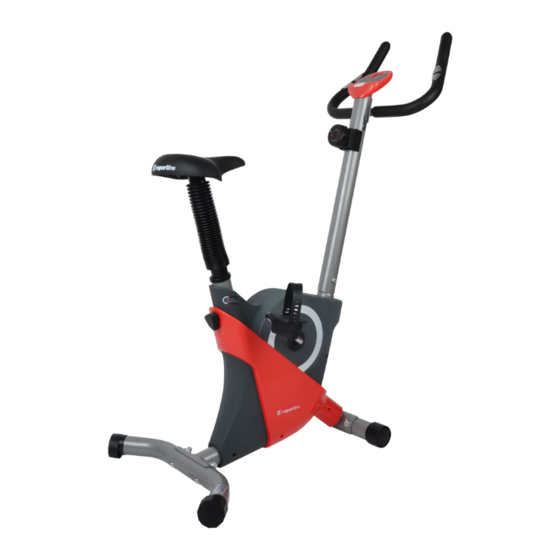
- Page 1 USER MANUAL - EN IN 8056 Magnetic Upright Bike inSPORTline Yanti...
-
Page 2: Table Of Contents
CONTENTS IMPORTANT SAFETY INSTRUCTIONS ......................3 PARTS LIST ................................4 HARDWARE PACKING LIST.......................... 6 TOOLS ................................6 OVERVIEW DRAWING ............................7 ASSEMBLY INSTRUCTIONS ..........................8 STEP 1: FRONT/REAR STABILIZERS AND RIGHT/LEFT FOOT PEDALS INSTALLATION ....8 STEP 2: SEAT POST, SEAT POST BELLOWS, AND SEAT CUSHION INSTALLATION ......9 STEP 3: HANDLEBAR POST INSTALLATION ................... -
Page 3: Important Safety Instructions
IMPORTANT: Read all instructions carefully before using this product. Retain this owner’s manual for future reference. The specifications of this product may vary from this photo, subject to change without notice. IMPORTANT SAFETY INSTRUCTIONS Basic precautions should always be followed, including the following important safety instructions when using this equipment. -
Page 4: Parts List
PARTS LIST Description Main Frame Ø50x1.5t Handlebar Ø25x1.5t Handlebar Post L650xØ50 Rear Stabilizer Ø50x1.5x380mm Flywheel Ø230 Front Stabilizer Ø50x1.5x360mm Tension Control Knob L=500 Seat Post Knob M16x1.5 Belt 280J4 Computer Wave Washer Seat Post Bushing Left Cover Right Cover Cross Recessed Pan Head Tapping Screw ST3x10 Washer Ø34.5x23x2.5t Bearing Nut I 15/16"... - Page 5 Big Curve Washer Ø10 Curve Washer Ø18xØ8x1.5t Washer Ø18xØ8x1.5t Big Spring Cross Recessed Pan Head Tapping Screw ST4x16 Small Spring Nylon Nut M8 Hexagon Bolt M5x30 Idler Arm Bearing 6000-2Z Big Washer Ø5xØ20x1.5t Cross Recessed Pan Head Bolt M4x12 Washer Ø24xØ40x3t Handlebar End Cap Ø25 Handlebar Foam Grip Ø30xØ24x455 Cross Recessed Pan Head Tapping Screw ST4.2x20...
-
Page 6: Hardware Packing List
HARDWARE PACKING LIST (34) Cap Nut M10 (35) Carriage Bolt M10x60 4 PCS 4 PCS (8) Seat Post Knob M16x1.5 1 PC (36) Big Curve Washer Ø10 4 PCS TOOLS Multi Hex Tool 5mm Allen Wrench with Phillips Screwdriver 1 PC 1 PC... -
Page 7: Overview Drawing
OVERVIEW DRAWING... -
Page 8: Assembly Instructions
ASSEMBLY INSTRUCTIONS STEP 1: FRONT/REAR STABILIZERS AND RIGHT/LEFT FOOT PEDALS INSTALLATION Tool: Multi Hex Tool Hardware: (34) Cap Nut M10 (35) Carriage Bolt M10x60 4 PCS (36) Big Curve Washer Ø10 4 PCS 4 PCS STABILIZERS INSTALLATION Position the Front Stabilizer (6) in front of the Main Frame (1) and align bolt holes. Attach the Front Stabilizer (6) onto the front curve of the Main Frame (1) with two M10 Cap Nuts (34), two M10x60 Carriage Bolts (35), and two Ø10 Big Curve Washers (36). -
Page 9: Step 2: Seat Post, Seat Post Bellows, And Seat Cushion Installation
STEP 2: SEAT POST, SEAT POST BELLOWS, AND SEAT CUSHION INSTALLATION Tool: Multi Hex Tool Hardware: (8) Seat Post Knob M16x1.5 1 PC Remove three Ø18xØ8x1.5t Washers (38) and three M8 Nylon Nuts (42) from underside of the Seat Cushion (27). -
Page 10: Step 3: Handlebar Post Installation
STEP 3: HANDLEBAR POST INSTALLATION Tool: 5mm Allen Wrench with Phillips Screwdriver Remove four M8x16 Hexagon Socket Pan Head Cap Bolts (24) and four Ø18xØ8x1.5t Curve Washers (37) from the Main Frame (1). Remove bolts with the 5mm Allen Wrench with Phillips Screwdriver provided. Connect the Sensor Wire (26) from the Main Frame (1) to the Extension Sensor Wire (33) from the Handlebar Post (3). -
Page 11: Step 4: Handlebar And Computer Installation
STEP 4: HANDLEBAR AND COMPUTER INSTALLATION Tool: 5mm Allen Wrench with Phillips Screwdriver Remove two M8x16 Hexagon Socket Pan Head Cap Bolts (24) and two Ø18xØ8x1.5t Curve Washers (37) from the Handlebar Post (3). Remove bolts with the 5mm Allen Wrench with Phillips Screwdriver provided. Insert the Hand Pulse Sensor Wires (53) into the hole on the Handlebar Post (3) and then pull the Hand Pulse Sensor Wires (53) out from the top end of the Handlebar Post (3). -
Page 12: Operating The Computer
OPERATING THE COMPUTER Computer Image for Item No. IN8056-2 Computer Image for Item No. IN8056-1 USING YOUR COMPUTER The computer can be activated by pressing the MODE button or by pedaling. If you leave the equipment idle for 4-5 minutes, the power will turn off automatically. BUTTON FUNCTIONS Press the MODE button to select one of the functions of the computer. -
Page 13: Adjustments
to zero. HOW TO INSTALL THE BATTERIES 1. Remove the battery cover on the back of the computer. 2. Place two size AAA batteries into the battery housing. 3. Insure batteries are correctly positioned and battery springs are in proper contact with batteries. 4. -
Page 14: Maintenance
MAINTENANCE CLEANING The upright bike can be cleaned with a soft clean damp cloth. Do not use abrasives or solvents on plastic parts. Please wipe your perspiration off the upright bike after each use. Be careful not to get excessive moisture on the computer display panel as this might cause an electrical hazard or electronics to fail. - Page 15 SHOULDER LIFTS Lift your right shoulder toward your ear for one count. Then lift your left shoulder up for one count as you lower your right shoulder. SIDE STRETCHES Open your arms to the side and lift them until they are over your head. Reach your right arm as far toward the ceiling as you can for one count.
- Page 16 INNER THIGH STRETCH Sit with the soles of your feet together and your knees pointing outward. Pull your feet as close to your groin as possible. Gently push your knees toward the floor. Hold for 15 counts. TOE TOUCHES Slowly bend forward from your waist, letting your back and shoulders relax as you stretch toward your toes. Reach as far as you can and hold for 15 counts.
-
Page 17: Terms And Conditions Of Warranty, Warranty Claims
CALF/ACHILLES STRETCH Lean against a wall with your left leg in front of the right and your arms forward. Keep your right leg straight and the left foot on the floor; then bend the left leg and lean forward by moving your hips toward the wall. Hold, then repeat on the other side for 15 counts. - Page 18 +420 556 300 970, objednavky@insportline.cz Warranty Claims: +420 556 770 190, Mobile: +420 604 853 019, reklamace@insportline.cz Service: +420 556 770 190, Mobile: +420 604 853 019, servis@insportline.cz Fax: +420 556 770 192, (Service +420 556 770 191) Web: www.insportline.cz, www.worker.cz, www.worker-moto.cz...
- Page 19 Bratislavska 36, 911 05 Trencin, Slovakia CRN: 36311723, VAT ID: SK2020177082 Orders: +421(0)326 526 701, +421(0)917 649 192, objednavky@insportline.sk Warranty Claims: +421(0)326 526 701, +421(0)918 408 519, reklamacie@insportline.sk Fax: +421(0)326 526 705 Web: www.insportline.sk, www.worker.sk, www.worker-moto.sk Date of Sale: Stamp and Signature of Seller:...
Need help?
Do you have a question about the IN 8056 and is the answer not in the manual?
Questions and answers