Table of Contents
Advertisement
Quick Links
Advertisement
Table of Contents

Subscribe to Our Youtube Channel
Related Manuals for Insportline IN 8244 Varis


Summary of Contents for Insportline IN 8244 Varis
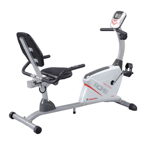
- Page 1 USER MANUAL - EN IN 8244 Recumbent inSPORTline Varis...
-
Page 2: Table Of Contents
CONTENTS IMPORTANT SAFETY INSTRUCTIONS......................3 OVERVIEW DRAWING............................4 PARTS LIST................................5 HARDWARE PACKING LIST...........................7 TOOLS..................................7 ASSEMBLY INSTRUCTIONS..........................8 STEP 1: REAR MAIN FRAME INSTALLATION.....................8 STEP 2: FRONT AND REAR STABILIZERS INSTALLATION..............9 STEP 3: FRONT HANDLEBAR POST AND FOOT PEDALS INSTALLATION.........10 STEP 4: SEAT SLIDING TUBE, BACK / SEAT SUPPORT BRACKET, AND HANDLEBAR INSTALLATION..............................11 STEP 5: COMPUTER AND SEAT/BACK CUSHIONS INSTALLATION.............12 OPERATING THE COMPUTER...........................13... -
Page 3: Important Safety Instructions
IMPORTANT: Read all instructions carefully before using this product. Retain this owner’s manual for future reference. The specifications of this product may vary from this photo, subject to change without notice. IMPORTANT SAFETY INSTRUCTIONS Basic precautions should always be followed, including the following important safety instructions when using this equipment. -
Page 4: Overview Drawing
OVERVIEW DRAWING... -
Page 5: Parts List
PARTS LIST Description Front Stabilizer End Cap Front Stabilizer Cap Nut M10 Curve Washer Ø10 Screw ST4.2x25 Bolt M10x57 Front Handlebar Post Cover Middle Section Hand Pulse Sensor Wire L=1000mm Pan Head Phillips Self Drilling Screw ST4.2x25 Right Cover Belt 330J6 Right Foot Pedal YH-30X Crank Washer Ø34.5xØ23x2.5... - Page 6 Washer Ø8xØ16x1.5 Bolt M8x30 Rear Stabilizer End Cap Idle Wheel Bracket Curve Washer Ø8xØ20x2 Washer Ø6xØ12x1 Washer Ø10.2xØ14x1 Bearing 6000ZZ Bolt M6x10 Big Washer Ø8xØ20x2 Rear Main Frame Seat Cushion 250x345x40 Back Cushion 310x345x40 Bolt M6x15 Big Washer Ø6xØ18x1.5 Back and Seat Support Bracket End Cap 23x53x2 Seat Sliding Tube Back and Seat Support Bracket Handlebar Foam Grip Ø30xØ24x510...
-
Page 7: Hardware Packing List
Eyebolt M6x36 Screw ST2.9x12 Cap Nut M8 Spring Washer Ø6xØ11.2x2 Tension Bracket Rubber Bolt Nut M8 Cover Cap Ø40xØ25x10 HARDWARE PACKING LIST (3) Cap Nut M10 (6) Bolt M10x57 4PCS (4) Curve Washer Ø10 4PCS 4PCS (45) Big Washer Ø8xØ20x2 (57) Bolt M8x45 (40) Curve Washer Ø8xØ20x2 2PCS... -
Page 8: Assembly Instructions
Multi Hex Tool 1 PC ASSEMBLY INSTRUCTIONS STEP 1: REAR MAIN FRAME INSTALLATION Tools: Allen Wrench S6 Remove two M8x30 Bolts (37), four M8x15 Bolts (72), and six Ø8xØ16x1.5 Washers (36) from the Rear Main Frame (46). Remove bolts with the S6 Allen Wrench provided. Connect the Middle Section Hand Pulse Sensor Wires (8) from the Rear Main Frame (46) to the Extension Hand Pulse Sensor Wires II (70) from the Front Main Frame (21). -
Page 9: Step 2: Front And Rear Stabilizers Installation
STEP 2: FRONT AND REAR STABILIZERS INSTALLATION Tools: Multi Hex Tool Hardware: (3) Cap Nut M10 (6) Bolt M10x57 4PCS (4) Curve Washer Ø10 4PCS 4PCS Position the Front Stabilizer (2) in front of the Front Main Frame (21) and align bolt holes. Attach the Front Stabilizer (2) onto the front curve of the Front Main Frame (21) with two M10 Cap Nuts (3), two Ø10 Curve Washers (4), and two M10x75 Bolts (6). -
Page 10: Step 3: Front Handlebar Post And Foot Pedals Installation
STEP 3: FRONT HANDLEBAR POST AND FOOT PEDALS INSTALLATION Tools: Multi Hex Tool with Phillips Screwdriver S10, S13, S14, S15 Allen Wrench S6 Remove one Ø8xØ20x2 Curve Washer (40), one M8x15 Bolt (72), four M8x10 Bolts (35) and four Ø8xØ16x1.5 Washers (36) from the Front Main Frame (21). -
Page 11: Step 4: Seat Sliding Tube, Back / Seat Support Bracket, And Handlebar Installation
Tighten the pedal shaft of Left Foot Pedal (69) with the Multi Hex Tool with Phillips Screwdriver provided. Insert pedal shaft of Right Foot Pedal (12) into threaded hole in right Crank (13). Turn the pedal shaft by hand in the clockwise direction until snug. -
Page 12: Step 5: Computer And Seat/Back Cushions Installation
Adjust the seat position and insert the Round Knob (60) and Triangle Knob (23). Turn the Round Knob (60) and Triangle Knob (23) in the clockwise direction to tighten. Attach the Handlebar (68) onto the Back and Seat Support Bracket (53) with two M8x45 Bolts (57), two Ø8xØ20x2 Curve Washers (40), two Ø8xØ20x2 Big Washers (45), and two M8 Cap Nuts (77). -
Page 13: Operating The Computer
OPERATING THE COMPUTER SPECIFICATION FUNCTION RANGE TIME 0:00-99:59 min:sec SPEED 0.0-99.9 km/h DIST (DISTANCE) 0.0-999.9 km CAL (CALORIES) 0.0-999.9 kcal ODO (ODOMETER) 0.0-9999 km 40-239 beats/min (PULSE) USING YOUR COMPUTER The computer can be activated by pressing the buttons or by pedaling. If you leave the equipment idle for approximate 4 minutes, the power will turn off automatically. -
Page 14: Adjustments
DIST (DISTANCE): Displays the accumulative distance traveled during workout. You may also pre-set target distance in STOP mode before training. To set DISTANCE press the MODE button until you see the DIST displays on the screen. Press the SET button to change the distance. Press the RESET button to clear the target distance to zero. -
Page 15: Adjusting The Rear Stabilizer End Cap
ADJUSTING THE REAR STABILIZER END CAP Turn the rear stabilizer end cap on the rear stabilizer as needed to level the recumbent bike. ADJUSTING THE SEAT FORWARD OR BACK Release the triangle knob from the rear main frame. Turn the round knob in a counterclockwise direction until it can be pulled out. -
Page 16: Warm Up And Cool Down Routine
when in use. recumbent bike. 1. Remove the computer console and verify the wires that come from the computer console are properly connected to the wires that come from the front handlebar post. There is no display on the 2. Check if the batteries are correctly positioned and battery springs are in computer console. - Page 17 SIDE STRETCHES Open your arms to the side and lift them until they are over your head. Reach your right arm as far toward the ceiling as you can for one count. Repeat this action with your left arm. QUADRICEPS STRETCH With one hand against a wall for balance, reach behind you and pull your right foot up.
-
Page 18: Terms And Conditions Of Warranty, Warranty Claims
Extend your right leg. Rest the sole of your left foot against your right inner thigh. Stretch toward your toe as far as possible. Hold for 15 counts. Relax and then repeat with left leg. CALF/ACHILLES STRETCH Lean against a wall with your left leg in front of the right and your arms forward. Keep your right leg straight and the left foot on the floor;... - Page 19 +420 556 300 970, objednavky@insportline.cz Warranty Claims: +420 556 770 190, Mobile: +420 604 853 019, reklamace@insportline.cz Service: +420 556 770 190, Mobile: +420 604 853 019, servis@insportline.cz Fax: +420 556 770 192, (Service +420 556 770 191) Web: www.insportline.cz, www.worker.cz, www.worker-moto.cz...
- Page 20 Bratislavska 36, 911 05 Trencin, Slovakia CRN: 36311723, VAT ID: SK2020177082 Orders: +421(0)326 526 701, +421(0)917 649 192, objednavky@insportline.sk Warranty Claims: +421(0)326 526 701, +421(0)918 408 519, reklamacie@insportline.sk Fax: +421(0)326 526 705 Web: www.insportline.sk, www.worker.sk, www.worker-moto.sk Date of Sale: Stamp and Signature of Seller:...
Need help?
Do you have a question about the IN 8244 Varis and is the answer not in the manual?
Questions and answers