Advertisement
Quick Links
Advertisement

Related Manuals for Ripmax Bullet


Summary of Contents for Ripmax Bullet
- Page 1 INSTRUCTION MANUAL...
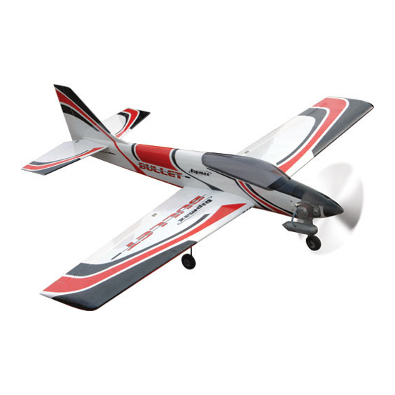
- Page 2 Congratulations on your purchase of the Bullet ARTF - the first Almost Ready to Fly version of this classic low- winger. Based on the original and timeless Bullet design, the new Ripmax Bullet ARTF has been scaled up by 10% to make to most of today's more powerful engines.
- Page 3 STEP 4 Install your servos as shown using the screws supplied with your radio noting that the servo output arms face towards the front of the wing. STEP 5 The wings and ailerons are supplied with the hinges loose fitted, ready for installation. Remove both ailerons and ensure that the hinges are inserted mid-way in their slots.
- Page 4 STEP 9 Using side cutters, trim off any excess screw thread that passes through the moulded horn plate. STEP 10 Use a small length of tape to hold each of the ailerons at their neutral position while you complete the aileron linkages.
- Page 5 STEP 14 Install both undercarriage legs ensuring that they push down fully into their slots. STEP 15 Locate the undercarriage retaining saddle clamps. Note that two are used per leg. Pilot drill the undercarriage mounting blocks for the clamps - one at the inner and one at the outer end of the leg - and retain with the wood screws supplied.
- Page 6 STEP 19 Insert the brace half-way into one wing panel using the centre-line as a guide. Wipe off any excess epoxy. STEP 20 Protect the covering with masking tape, then spread sufficient slow setting epoxy over the opposite panel joiner slot, wing joiner and root rib. Bring the two panels together ensuring the epoxy fills the join.
- Page 7 STEP 24 Glue the plywood wing bolt reinforcing plate in place using 5 minute epoxy. Use the wing bolts to hold the plate in position while the epoxy cures but take care not to get adhesive on the threads. STEP 25 Protect the fuselage with clear tape or film so that you do not accidentally glue the wing to the fuselage in this step.
- Page 8 STEP 29 Slide the tailplane into its pre-cut slot in the rear of the fuselage. Ensure that it is square to the fuselage and centred in its slot using a long ruler or string as shown in the diagram. STEP 30 Mark the tailplane on the top and bottom where it enters the fuselage using a soft, water-soluble pen.
- Page 9 STEP 34 Check that the tailplane is correctly aligned, square to the fuselage and level with the wings. Glue in position using cyanoacrylate glue (cyano). Alternatively, if using epoxy, use masking tape to protect the covering (removing it as soon as you are satisfied with the alignment and before the epoxy cures).
- Page 10 STEP 39 Now slide the first elevator into position ensuring that the joiner enters the hole in the elevator and all three hinges enter their pre-cut slots in the tailplane. Ensuring a gap-free hinge line, align the end of the elevator with the tip of the tailplane.
- Page 11 STEP 44 Hold your engine steady and mark the positions of the mounting holes on the mount. STEP 45 Remove the engine and pilot drill four holes through the engine mounting beams to suit the self tapping screws supplied. Screw the engine to the mount. STEP 46 Locate the nosewheel mount and screw it in position on the bulkhead using the self tapping screws provided.
- Page 12 STEP 49 Screw a plastic snap link onto the end of the throttle pushrod. Slide the pushrod into its outer and connect the snap link to the carburettor throttle lever. Retain using a short length of fuel tube as shown. STEP 50 You can now install your servos in the pre-fitted servo tray.
- Page 13 STEP 54 Now screw the horn to the rudder. STEP 55 The screws thread into the moulded horn plate on the other surface of the rudder. STEP 56 Carry out the above 5 steps again to complete the elevator linkage. STEP 57 Move to the radio bay and complete each linkage by screwing on a nylon clevis and connecting to the...
- Page 14 STEP 59 The tank is installed in its bay via the radio bay. Fit and identify your fuel tubes, then feed the tank into position, drawing the fuel tubes out through the hole in the centre of the firewall. Connect the fuel line to your engine, pressure line to the silencer and blank off the vent line.
-
Page 15: Control Throws
Ensure the wing bolts are tight. While the Bullet is not suitable as a first model, it does make an excellent second low-wing model with reduced control throws and an engine from the lower end of the range. In this case, we recommend that your completed model is checked over and test flown by a competent pilot first. - Page 16 Distributed to your local model shop by: Ltd., 241 Green Street, Enfield, EN3 7SJ. United Kingdom Made in China Page 16...
Need help?
Do you have a question about the Bullet and is the answer not in the manual?
Questions and answers