Advertisement
Quick Links
Advertisement

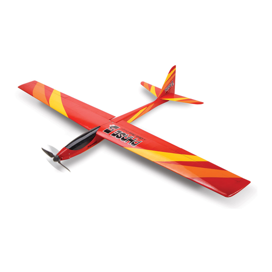
Summary of Contents for Ripmax Phase 5 E
- Page 1 Instruction Manual Bauanleitung A-CF011...
- Page 2 CONTENTS INHALT PAGE / SEITE General Notices Wichtige Hinweise 2 / 3 Contents Inhalt Required to Complete erforderliches Zubehör Stages Schritte 5 - 15 Control Throws Ruderausschläge Pre-Flight Checks Vorflug Checks Spare Parts Ersatzteile Flying the Phase 5 Den Phase 5 Fliegen Completed Model Fertiges Modell Balancing...
-
Page 3: General Notices
Teilen in Berührung kommen! Denken Sie level directly in line with other people/animals as this Ripmax shall not be liable for any loss, consequential loss, damage auch an Ihre Haustiere! Ripmax Produkte sind häufig nur ein Teil einer ganzen will increase the risk of injury. - Page 4 INSTRUCTIONS / ANLEITUNG INSTRUCTIONS / ANLEITUNG Stage Contents / Inhalt Schritt Take a moment to identify each of the par ts supplied and read through these The wings and ailerons are supplied with the hinges loose fitted, ready for installation. Remove both ailerons and ensure that the instructions before commencing assembly.
- Page 5 INSTRUCTIONS / ANLEITUNG INSTRUCTIONS / ANLEITUNG Stage Stage Schritt Schritt Fit suitable 500mm extension lead to your aileron servo. It is a Remove the film from the pre-cut slot in the aileron. Gently push good idea to use a lead-lock, a turn of insulation tape or heat the aileron horn into the slot, making sure that the horn is at 90 shrink tube over the joint for additional security.
- Page 6 INSTRUCTIONS / ANLEITUNG INSTRUCTIONS / ANLEITUNG Stage Stage Schritt Schritt Trim off the excess pushrod wire using side cutters. Repeat the Now locate the wing dowels and epoxy one of these into the front procedure for the second aileron in exactly the same way. of each wing at the leading edge and one plastic peg in the rear of one wing panel as shown.
- Page 7 INSTRUCTIONS / ANLEITUNG INSTRUCTIONS / ANLEITUNG Stage Stage Schritt Schritt Locate the slots at the rear of the fuselage on the fin for the Slide the pushrod through the connector on the servo arms. With tailplane front joiner and carefully trim the covering away as the radio ‘ON’...
- Page 8 INSTRUCTIONS / ANLEITUNG INSTRUCTIONS / ANLEITUNG INSTRUCTIONS / ANLEITUNG Stage Stage Schritt Schritt Feed the control wires down the tubes in the fuselage and with Fit the brushless motor using the screws supplied into the the servo at its neutral position, reposition the servo arm and captive nuts pre-fitted in the motor mount.
- Page 9 INSTRUCTIONS / ANLEITUNG INSTRUCTIONS / ANLEITUNG Stage Stage Schritt Schritt Locate the two tailplane halves and joining rods, then push the There are a series of cooling holes in the underside of the larger rod into the rear tube of one tailplane half and the smaller fuselage.
- Page 10 Modell an der Unterseite des Flügels nahe des Spare parts are available for the Phase 5 from all Ripmax stocked model shops. In case of any difficulty, any product queries, or to locate Rumpfes, und geben Gewicht dazu, oder verändern die Position your local Ripmax stockist, please visit www.ripmax.com...
- Page 11 Copying or reproduction, even in parts require written schriftlicher Genehmigung der Ripmax Ltd. permission of Ripmax Ltd. Made in China Manufactured for and distributed to your local model shop by: Ripmax Ltd., 241 Green Street, Enfield, EN3 7SJ. United Kingdom.


Need help?
Do you have a question about the Phase 5 E and is the answer not in the manual?
Questions and answers