Advertisement
Quick Links
Advertisement

Related Manuals for Ripmax WOT 4 XL Mk2


Summary of Contents for Ripmax WOT 4 XL Mk2
- Page 1 Part No: A-CF004...
- Page 2 WOT 4 XL - Instructions The Designer Chris Foss outside his factory in 1990 Chris Foss Chris Foss The fascination of flight captured Chris' imagination early on in his life when he started building, from kits and plans, simple free flight gliders and rubber powered models. By his early teens, Chris was already experimenting with his own designs, several of which have been featured as constructional plans in various aeromodelling magazines.
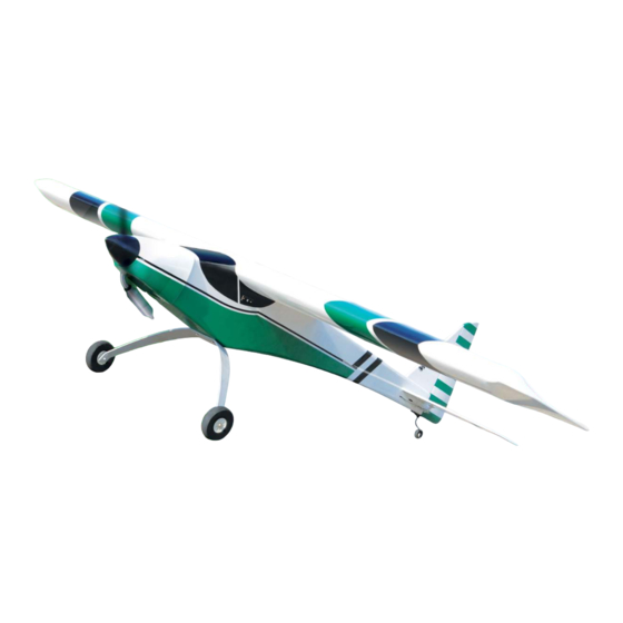
- Page 3 WOT 4 XL - Instructions Introduction Congratulations on your purchase of the WOT 4 XL Mk2 ARTF - the first 'Large' Almost Ready to Fly version of this timeless classic. Described as the most exciting sports aerobatic models of all time, it can be assembled in the minimum of time.
- Page 4 WOT 4 XL - Instructions STEP 6 Now tie each aileron servo's lead to the length of cotton already in the wing panels and carefully pull the leads through to the centre of the wing using the cotton thread. Lift out the servo connector through the hole then retain the servo lead with a short length of tape to stop the lead pulling back into the wing.
- Page 5 WOT 4 XL - Instructions STEP 12 Remove any sharp edges from the cut mounting screws using a fine hand file. STEP 13 Use a small length of tape to hold each of the ailerons at their neutral position. Ensure that both aileron servos are centred. Thread a locknut and clevis onto an aileron pushrod, connect it to the control horn and secure with a short length of fuel tubing.
-
Page 6: Tailplane And Fin
WOT 4 XL - Instructions STEP 18 Coat the inside of the corresponding slot in the wing panel and one half of the brace with rapid setting epoxy. Ensure that adequate epoxy is used to fully cover all surfaces. Insert the brace half-way into one wing panel using the centre-line as a guide. - Page 7 WOT 4 XL - Instructions STEP 24 Centred to the line drawn in the step above, mark two further points 18mm apart. These are used to align the tailplane in the fuselage. 18mm STEP 25 Slide the tailplane into its pre-cut slot in the rear of the fuselage.
- Page 8 WOT 4 XL - Instructions STEP 30 Once the epoxy has cured, slide the fin into its pre-cut slot in the top of the fuselage. Ensure that it is pushed down far enough to touch the top of the tailplane. Mark the fin on both sides where it enters the fuselage using a soft, water-soluble pen.
- Page 9 WOT 4 XL - Instructions STEP 36 Locate the pre-bent tailwheel assembly and fit the tailwheel using the collet supplied using a small drop of threadlock to secure the grubscrew. STEP 37 Screw the tailwheel assembly in position with the tailwheel wire in line with the rear of the fuselage.
- Page 10 WOT 4 XL - Instructions Fuselage, Engine & Radio STEP 42 Mount the two halves of the engine mount to the firewall using the bolts supplied into the captive nuts already installed in the bulkhead. STEP 43 Hold your choice of engine in place on the engine mount ensuring that the distance from the front of the bulkhead to the prop driver is 155mm.
- Page 11 WOT 4 XL - Instructions STEP 48 Undercarriage Wheel Pass the mounting screw through the wheel, screw on a plain nut, then pass through the main undercarriage. Now fit a nyloc nut on the inside. Hold the inner nut still and tighten the nyloc nut. Check the wheel rotates freely.
- Page 12 WOT 4 XL - Instructions STEP 54 Locate the closed loop horn and install it in the pre-drilled hole in the rudder in line with the slots in the fuselage using the nuts and washers as shown. Use a threadlocking compound on the nuts to ensure they do not loosen due to engine vibration.
- Page 13 WOT 4 XL - Instructions STEP 60 Do not overtighten the control horn mounting screws - you don't want to crush the elevator. Turn the model over and trim off any excess thread using side cutters. STEP 61 Pass the 'Y' shaped elevator pushrod through the fuselage from the radio bay.
- Page 14 WOT 4 XL - Instructions STEP 66 The tank is installed in its bay via the radio bay. Fit and identify your fuel tubes, then feed the tank into position, drawing the fuel tubes out through the hole in the centre of the firewall. Connect the fuel line to the engine, pressure to the exhaust and block the fill line.
- Page 15 Spare Parts and Service Spare parts are available for the WOT 4 XL ARTF from all Ripmax stocked model shops. In case of any difficulty, any product queries, or to locate your local Ripmax stockist, please write to the address below or visit www.ripmax.com Always fly responsibly and safely.
Need help?
Do you have a question about the WOT 4 XL Mk2 and is the answer not in the manual?
Questions and answers