Advertisement
Quick Links
Advertisement

Related Manuals for Ripmax WOT 4 MK2


Summary of Contents for Ripmax WOT 4 MK2
- Page 2 WOT 4 - Instructions The Designer Chris Foss outside his factory in 1990 Chris Foss Chris Foss The fascination of flight captured Chris's imagination early on in his life when he started building, from kits and plans, simple free flight gliders and rubber powered models. By his early teens, Chris was already experimenting with his own designs, several of which have been featured as constructional plans in various aeromodelling magazines.
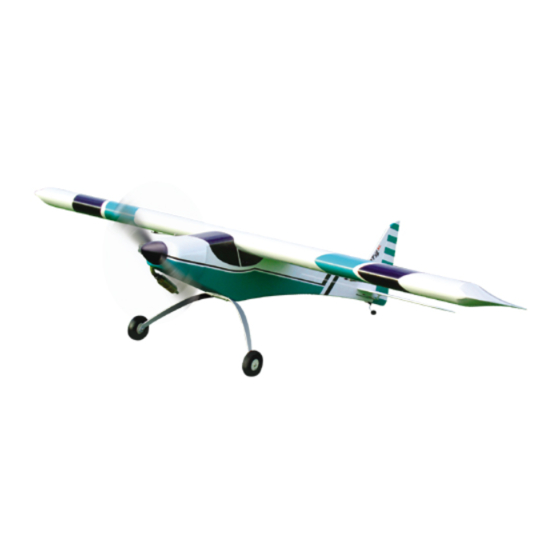
- Page 3 WOT 4 - Instructions Introduction Congratulations on your purchase of the WOT 4 Mk2 ARTF - the first Almost Ready to Fly version of his timeless classic. Described as the most exciting sports aerobatic models of all time, it can be assembled in the minimum of time.
- Page 4 WOT 4 - Instructions STEP 6 Screw the aileron servos in position using the mounting screws, rubber grommets and ferrules supplied with your radio. Note that the output arms face towards the rear of the wing. STEP 7 Locate the aileron control horns. They are screwed in position on the ailerons in line with the aileron servo's output arm.
- Page 5 WOT 4 - Instructions STEP 12 Trim off the excess pushrod wire using side cutters. Repeat the procedure for the second aileron in exactly the same way. STEP 13 Adjust the pushrods to ensure that the ailerons are centred with the aileron servos at their neutral position.
- Page 6 WOT 4 - Instructions Installing the Undercarriage STEP 18 Locate the aluminium main undercarriage, wheels and wheel mounting hardware (mounting screws, plain and nyloc nuts). STEP 19 Pass the mounting screw through the wheel, screw on a plain nut, then pass through the main undercarriage.
-
Page 7: Tailplane And Fin
WOT 4 - Instructions Tailplane and Fin STEP 24 Slide the tailplane into its pre-cut slot in the rear of the fuselage. Ensure that it is square to the fuselage and centred in its slot using a long ruler or string as shown in the diagram on the right. - Page 8 WOT 4 - Instructions STEP 30 Remove the fin and cut away the covering from just below the marked lines to give a film-free surface for the glue to bond. IMPORTANT NOTE: Ensure that only the film is cut - not the fin - as this will seriously weaken the structure. STEP 31 Using a sharp knife, carefully remove the film from the fuselage from just in front and behind the fin mounting slot as shown so that the fin has a completely...
- Page 9 WOT 4 - Instructions STEP 36 Ensure that the rudder is aligned to the top of the fin and there is free movement left and right plus a gap-free hinge line. Now apply a couple of drops of thin cyano to each side of each hinge taking care not to allow the adhesive to run through the gap onto the other side of the model.
-
Page 10: Radio Installation
WOT 4 - Instructions Elevator Throttle Radio Installation Servo Servo STEP 42 Install your throttle and elevator servos in the pre-fitted servo tray. Note the orientation of the servo outputs. Now glue the two servo spacers to the tray. These raise the height of the rudder servo for additional clearance of the elevator servo. - Page 11 WOT 4 - Instructions STEP 48 Slip the bent pushrod through the servo horn and fit a moulded swing-in keeper. Now trim off the excess length of wire, refit the horn and test the operation of the elevator. Engine Fitting and Throttle Linkage STEP 49 The engine mount supplied with the WOT 4 is a two part design.
- Page 12 WOT 4 - Instructions STEP 54 Locate the throttle pushrod outer sleeve. Install the tube with a drop of cyano to secure. STEP 55 Trim off the excess length of tube inside the radio bay as shown. STEP 56 Form a 'Z' bend in the throttle pushrod. Fit to the carburettor throttle lever and slide the pushrod into its outer.
- Page 13 WOT 4 - Instructions STEP 60 Fit the assembled tank bung and tighten the retaining screw. Take care not to over-tighten this screw. Test that the tank is leak- proof. STEP 61 The tank is installed in its bay via the radio bay. Fit and identify your fuel tubes, then feed the tank into position, drawing the fuel tubes out through the hole in the centre of the firewall.
-
Page 14: Control Throws
Spare Parts and Service Spare parts are available for the WOT 4 ARTF from all Ripmax stocked model shops. In case of any difficulty, any product queries, or to locate your local Ripmax stockist, please write to the address below or visit www.ripmax.com Always fly responsibly and safely. - Page 15 WOT 4 - Instructions Notes :...
Need help?
Do you have a question about the WOT 4 MK2 and is the answer not in the manual?
Questions and answers