
Related Manuals for Ripmax J!VE Fun Fly


Summary of Contents for Ripmax J!VE Fun Fly
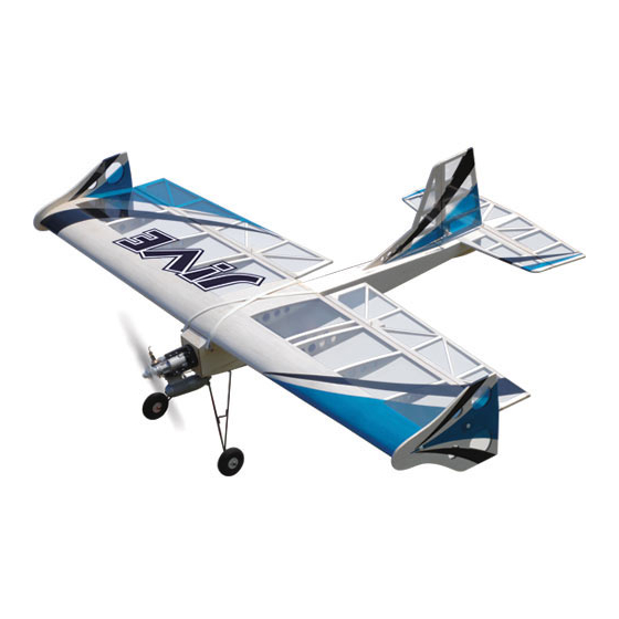
- Page 1 Instruction Manual Specification: Wingspan: 1332mm (51.3”) Length: 1055mm (41.5”) Weight: 1660g (Approx.) Radio: 4-5 Channel (Required) IC Engine: Irvine .36 or .39 (Recommended)
-
Page 2: Required To Complete
Introduction Congratulations on your purchase of the J!VE Fun Fly. This fun model is ideal for use as a sports model or top level competition machine using its large control surfaces and detachable Side Force Generators. Before you build the model, please read the instructions the whole way through to understand the construction sequence. - Page 3 Step 1 The hinges are all supplied loose fitted ready for installation. Glue the hinges into the ailerons with a couple of drops of thin cyano on each to secure. Ensure the glue soaks into the hinge & surrounding wood. Step 2 Slot the aileron onto the hinges, ensuring a gap free hinge line and making sure both ailerons line up with...
- Page 4 Step 6 Cut away the film from the hole in the centre of the wing. You can now pull the string gently through the hole and feed out the extension lead. Step 7 Position the aileron servo in the wing with the horn pointing towards the wing tip and output arm towards the trailing edge of the wing.
- Page 5 Step 11 Turn the wing over and trim off any excess thread using side cutters. Step 12 Now hold the aileron pushrod wire firmly and attach a plastic clevis. Step 13 Clip the clevis onto the horn in the hole 2nd out from the surface of the wing.
- Page 6 Step 16 Slide the aileron servo horn over the wire, re-fit to the servo, then slide the swing-in keeper onto the wire and clip into place. Step 17 Trim the excess wire 2mm above the keeper using side cutters. Repeat this process for the other aileron servo. Step 18 If you wish to use the Side Force Generators, trim the covering away from the bolt holes on the wing tips.
- Page 7 Step 21 Install the “Aileron 1” and “Aileron 2” identification tags to the extension leads. Step 22 Secure the hinges in the tailplane using a couple of drops of cyano on each. Step 23 Slot the elevator onto the hinges keeping the hinge gap to a minimum and run thin cyano in the hinges on both sides, ensuring the glue soaks into the hinge and surrounding wood.
- Page 8 Step 26 Place the tailplane in position on the fuselage and turn it upside down. Carefully check that the tailplane is square and centred in relation to the fuselage. Now mark the position of the fuselage on the tailplane. Step 27 Using a sharp knife blade, carefully cut the film from the tailplane inside the marked lines.
- Page 9 Step 31 Carefully cut the film away from the fin slot. Step 32 Place the fin in its slot and mark the position of the fuselage on the film on the fin. Step 33 Mark the fuselage where the fin is positioned. Remove the fin then cut and remove the film from the fuselage so that the fin has a completely film free surface to bond to.
- Page 10 Step 36 Glue the fin in position in its slot in the fuselage. A great way to ensure the fin is perpendicular to the tailplane is to use an empty CD case or set square. Step 37 Just as you did with the fin, trim the excess film from the tab on the tail skid.
- Page 11 Step 41 Pilot-drill the holes for the retaining screws. Step 42 Screw the landing gear in position. Note that the undercarriage should be angled forwards. Step 43 Install the wheels by fitting a collet on the axle, then install the wheel, followed by another collet. Take care to ensure the wheel moves freely but doesn’t slide sideways on the axle.
- Page 12 Step 46 Cut the unused moulding away from the engine mount as shown and trim flush. Step 47 Assemble the mount and position in place on the firewall. Screw the mount in position but do not tighten the screws fully yet. Step 48 Position the engine on the mount, ensuring there is room for the fuel lines behind it and mark the engine...
- Page 13 Step 51 Bolt the silencer in position. Step 52 Assemble the bung for the fuel tank as shown. Bend the breather pipe up and place that high in the rubber bung, and the small pipe lower for the fuel feed. Use the supplied thin walled tubing for the clunk ensuring that the clunk doesn’t hit the back of the tank.
- Page 14 Step 56 Pilot-drill the servo mounting holes and screw them in place as shown right, noting the orientation. Use the rubber grommets & ferrules supplied with your radio. Step 57 Install the pushrod connector to the throttle servo horn and use a drop of cyano to secure the retaining nut in place.
- Page 15 Step 61 Cut the last hole off of the elevator horn and trim along the red lines shown in the diagram right. Step 62 Screw the clevis onto the elevator pushrod, and clip to the horn. Step 63 Slide the elevator pushrod down the pushrod tube in the fuselage and mark the position of the horn on the elevator.
- Page 16 Step 66 Connect the pushrod to the elevator horn and install the swing-in keeper. Step 67 Cut the film away from the rudder control horn mounting hole. Step 68 Assemble one half of the rudder closed loop horn as shown. Step 69 Install the horn in the rudder checking carefully that it is in the centre and tight.
- Page 17 Step 71 Loop one end of wire through one of the closed loop adaptors and slide the crimp tube over the looped wire. Crimp the tube on the wire gently using a pair of wire cutters at multiple points. For additional security use a drop of cyano too.
- Page 18 Step 76 Install the battery on a piece of foam behind the fuel tank using the same method as the fuel tank with the remaining Velcro straps. Step 77 Mark and cut a hole for the switch in the balsa on the right hand side of the fuselage.
-
Page 19: Control Throws
Do not miss out this important step! Spare Parts and Service Spare parts are available for the J!VE from all Ripmax stocked model shops. In case of any difficulty, any product queries, or to locate your local Ripmax stockist, please write to the address below or visit www.ripmax.com... -
Page 20: Flying Notes
Pre-Flight Checks • Completely charge your transmitter and receiver batteries before flying. • Carefully check your model over to ensure that all screws are tight and everything is well bonded. • Double-check the Centre of Gravity. • Check the control surfaces for both the correct throw and direction. Ensure that each surface moves freely, without any binding. • Ensure the wing bands are secure. Always fly the J!VE in a safe location at a recognised club. For further information on flying in the UK, please contact: British Model Flying Association (BMFA) Chacksfield House, Tel: (+44) 116 2440028 31 St Andrews Road,... - Page 21 Limbo To compete in limbo you have to fly under a ribbon as many times as possible in a designated time. You can loop around the ribbon or fly a tight circuit. The score stops when you run out of time or cut the ribbon. Typically an old VHS tape unreeled makes a great ribbon to fly under.
- Page 22 Photocopy to Use Club Competition Chart Climb and Glide Longest flight from 20 seconds of power. Name Score Limbo Perform as many passes under the limbo ribbon as possible in 2 minutes. Name Score Page 22...
- Page 23 Photocopy to Use Club Competition Chart Triple Thrash Perform three “Touch and Gos”, three rolls and three loops in the shortest time possible. Name Score Touch and Gos Perform as many touch and gos in the designated area in 2 Minutes. Name Score Page 23...
- Page 24 Always Fly Responsibly and Safely. Distributed to your local model shop by: Ripmax Ltd., 241 Green Street, Enfield, EN3 7SJ. United Kingdom Made in China...
Need help?
Do you have a question about the J!VE Fun Fly and is the answer not in the manual?
Questions and answers