Advertisement
Advertisement
Table of Contents

Subscribe to Our Youtube Channel
Related Manuals for Ripmax Acro Wot MK2 XL


Summary of Contents for Ripmax Acro Wot MK2 XL
- Page 2 Acro Wot XL - Instructions The Designer Chris Foss outside his factory in 1990 Chris Foss Chris Foss The fascination of flight captured Chris's imagination early on in his life when he started building, from kits and plans, simple free flight gliders and rubber powered models. By his early teens, Chris was already experimenting with his own designs, several of which have been featured as constructional plans in various aeromodelling magazines.
-
Page 3: Assembling The Wing
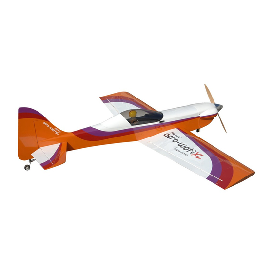
Acro Wot XL - Instructions Introduction Congratulations on your purchase of the Acro Wot XL Mk2 ARTF - the first Almost Ready to Fly large version of Chris Foss' classic low-winger. Its unbeatable combination of great looks and superb flying performance make it a must-have sports model! Assembly is quick and easy, but before commencing construction, please ensure that you read these instructions in their entirety. - Page 4 Acro Wot XL - Instructions STEP 6 Use a sharp knife to cut away the covering over the servo apertures in the underside of the wing. STEP 7 Prepare your aileron servos by connecting a suitable extension lead to each. It is a good idea to use a lead-lock, a turn of insulation tape or heatshrink tube over the joint for additional security.
- Page 5 Acro Wot XL - Instructions STEP 12 Do not overtighten the control horn mounting screws - you don't want to crush the aileron. Turn the model over and trim off any excess thread using side cutters. STEP 13 The complete aileron linkage is shown here, note the use of fuel tube keepers on both clevises for security, Do ensure that the locking nuts are firmly tightened against the clevises to avoid the pushrod unscrewing itself due to vibration.
-
Page 6: Fitting The Undercarriage
Acro Wot XL - Instructions STEP 18 When the wings are fitted to the fuselage the load spreading plate should be positioned as shown. Fitting the Undercarriage STEP 19 Locate the aluminium main undercarriage, wheels and wheel mounting hardware (axles, washers, nyloc nuts and collets). Pass the axle through the undercarriage leg then install the nyloc nut and tighten securely. -
Page 7: Assembling The Fuselage
Acro Wot XL - Instructions STEP 24 Screw the tailwheel assembly into place as shown. Assembling the Fuselage STEP 25 Using a sharp knife, carefully remove the film from the slot in both sides of the fuselage where the tailplane will mount. STEP 26 Trim away the covering to expose the slots for the elevator pushrod and rudder closed loop exits. - Page 8 Acro Wot XL - Instructions STEP 30 When the twin pushrod ends are visible in the tailplane slot cut the masking tape to allow the pushrods to spring apart. STEP 31 Use a small screwdrive or allen key to position the pushrod ends in line with the pushrod slots in the fuselage and gently ease the pushrod ends out of these slots.
- Page 9 Acro Wot XL - Instructions STEP 36 With the covering removed, the fin and tailplane are ready to be installed. If necessary, use a warm covering iron to ensure the edges of the film are firmly adhered. STEP 37 Slide the tailplane into place and check alignment - once happy run thin cyano glue along the edge of the tailplane/fuselage joint.
- Page 10 Acro Wot XL - Instructions STEP 42 In a similar manner to already described for the ailerons/wing, glue the hinges into the rudder and then in turn glue the exposed hinges into the fin and rear fuselage, ensuring that the rudder/fin/fuselage gap is minimised. STEP 43 Install elevator control horns in a similar manner to those fitted to the ailerons.
-
Page 11: Installing The Engine
Acro Wot XL - Instructions STEP 48 Centre the rudder and connect up the closed loop wires to the adapters in a similar manner to that use on the servo horn ends of the wires. STEP 49 Slide one of the brass tube crimps over one end of the tailwheel steering springs and make a 90 degree bend in the straight section around 15mm from the end as shown. - Page 12 Acro Wot XL - Instructions STEP 54 Offer up the captive nuts to the rear of the engine former, it is possible to position these using a single finger as shown, a small dab of thick grease can be used to hold the nut in position on your finger until it can be pressed into the corresponding hole in the former.
- Page 13 Acro Wot XL - Instructions STEP 60 Prepare the fuel tank for fitting by assembling the tank stopper with the feed, vent and fuel pipes. Ensure the clunk tube lengths are cut to allow the clunks to move around the tank without catching on the tank's base. Fit the assembled tank bung and tighten the retaining screw.
-
Page 14: Final Assembly
Acro Wot XL - Instructions Final Assembly STEP 66 Radio and ignition batteries should be wrapped in foam and then positioned as far forward as possible unless a particularly heavy engine is being used. Note the tape over the connectors to secure them together. STEP 67 Switches can be positioned as shown, this example has one switch on each side of the fuselage. -
Page 15: Control Throws
Spare Parts and Service Spare parts are available for the Acro Wot XL ARTF from all Ripmax stocked model shops. In case of any difficulty, any product queries, or to locate your local Ripmax stockist, please write to the address below or visit www.ripmax.com Always fly responsibly and safely.
Need help?
Do you have a question about the Acro Wot MK2 XL and is the answer not in the manual?
Questions and answers