Advertisement
Quick Links
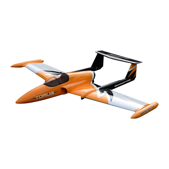
ARTF KIT.
Specification:
Wingspan: 2,286mm (90")
Length: 2,209mm (87")
Weight: 13.6 -15.4Kg (30 - 34 lbs)
(Approx.)
Radio: 7+ Channel (Required)
Turbine: 110 -160N (24 - 36 lbs)
(Required)
Servos: 10 x (20+ kg/cm)
(Required)
THE TORUS TURBINE MODEL IS DESIGNED FOR EXPERIENCED MODELLERS. THIS MODEL
IS NOT RECOMMENDED FOR BEGINNERS. TURBINE MODELS ARE FOR ADVANCED FLYERS
AND SHOULD NOT BE ATTEMPTED BY THOSE WITH INSUFFICENT BUILDING & FLYING
EXPERIENCE.THIS INSTRUCTION MANUAL IS FOR GUIDANCE ONLY. IF YOU ARE UNSURE
OF ANY MODEL BUILDING TECHNIQUES, SEEK HELP FROM AN EXPERIENCED MODELLER
OR CONTACT RIPMAX LTD, FOR ASSISTANCE. JET MODELS ARE DANGEROUS IF
CONSTRUCTION IS CARELESSLY OR INCORRECTLY CARRIED OUT. AS THE BUILDING
AND FLYING OF THIS KIT IS OUT OF OUR CONTROL AFTER POINT OF SALE, NO LIABILITY IS
ACCEPTED BY RIPMAX LTD. FOR ANY ACCIDENT OR LOSS, HOWEVER CAUSED. PURCHASE
OF THIS KIT IMPLIES ACCEPTANCE OF THESE CONDITIONS BY THE PURCHASER.
TO DECLINE THESE TERMS, RETURN UNUSED KIT TO YOUR SUPPLIER FOR A FULL REFUND.
Read through this manual carefully
before you begin building and follow
it during construction.
Safety Precautions
Advertisement

Related Manuals for Ripmax BOOMERANG TORUS


Summary of Contents for Ripmax BOOMERANG TORUS
- Page 1 AND FLYING OF THIS KIT IS OUT OF OUR CONTROL AFTER POINT OF SALE, NO LIABILITY IS ACCEPTED BY RIPMAX LTD. FOR ANY ACCIDENT OR LOSS, HOWEVER CAUSED. PURCHASE OF THIS KIT IMPLIES ACCEPTANCE OF THESE CONDITIONS BY THE PURCHASER.
- Page 2 NOTES ON HORN POSITIONS Mount the horns so the clevis holes are 1/4" (6mm) behind the hinge line for the ailerons to give differential and on the hinge line for rudders and elevators. But on the FLAP horns, move the horn bolt rearwards about 1"(25mm.) from hinge line and drill the hole for the horn bolt back so that the hole in the flap is a full 3/4"...
- Page 3 Follow Sullivan horn instructions. Supplied Not Supplied Use 1” 4-40 stud for pushrods Supplied 2.6 x 12mm TP Screw Supplied...
- Page 4 Tip Tank Installation 2.5mm Hex Wrench 4 x 10mm Bolt 4 x 10mm Bolt Regular wing tips. 4 x 10mm Bolt Fix the alloy rods in the wing with the bolts supplied. Use glossy plastic packing tape or similar over the wing to ensure release, then use 5 minute epoxy glue in the wing tips.
- Page 5 3 x16mm TP Screw Not Supplied Not Supplied 3 x16mm TP Screw Not Supplied Up to 2.75 inches Not Supplied...
- Page 6 1.25 metre extension Be sure to glue the rudder hinges securely. This is vital for safe flying! 2.6 x 12mm TP Screw 1 metre extension 2.6 x 12mm TP Screw Cut away covering film Cut away covering film...
- Page 7 Supplied. Supplied. 2.6 x 12mm TP Screw Use short lengths of 4-40 stud and Sullivan clevises and horns supplied. 2.6 x 12mm TP Screw...
- Page 8 Rudders Assemble left and right sides the same way Supplied 4-40 stud pushrod Supplied Assemble left and right sides the same way...
- Page 9 Assemble left and right sides the same way 8mm Alloy Rods 6mm Alloy Rods Carbon fibre spars 4 x 10mm Bolt 4 x 10mm Bolt Carbon fibre spars 6mm Alloy Rods 8mm Alloy Rods...
- Page 10 4 x 20mm Bolt 4 x 20mm Bolt 4 x 20mm Bolt Additional safety fitting to stabilisor With tailplane (Stab.) firmly screwed down, pass a 3.6mm drill through the holes in the fins and drill a hole through the metal tongue projecting down from the Stab.
- Page 11 55mm Not Supplied Not Supplied Not Supplied Not Supplied Not Supplied Not Supplied 2 x 8mm TP Screw 2 x 8mm TP Screw...
-
Page 12: Turbine Installation
Turbine installation Remove the cross braces which are marked "cut" by cutting at the dotted 4 x 15mm Bolt lines. Do the same with the cross braces marked "cut" in the hatch. You Cut off at the may prefer to fix the turbine with the dotted line 4mm bolts and spike nuts supplied or use self tapping screws if preferred... - Page 13 Battery and RX 2.6 x 12mm TP Screw 2.6 x 12mm TP Screw Fuel and Ancillaries Tray 2.6 x 12mm TP Screw 2.6 x 12mm TP Screw...
- Page 14 It is essential to use Velcro double sided Straps or large tie wraps through the vertical parts of the formers to fix the fuel tank. 2.6 x 12mm TP Screw 4 x 15mm Bolt 4mm Washer 4mm Blind Nut 4mm Blind Nut 4mm Washer 4 x 15mm Bolt...
- Page 15 25mm 25mm 25mm 20mm ELEVATOR AILERON 40mm The flap should drop as near to 90 degrees as possible 40mm RUDDER FLAP For your first flights, take the CG with the model “dry” all assembled with the retracts down and the hatch removed. If you are using lightweight batteries you will need to add up to 16 ounces of weight in the nose.
- Page 16 Seek help if necessary. In no case shall Ripmax Ltd. warranty cover any product which is not manufactured by Ripmax Ltd. The liability to the manufacturer cannot exceed the original cost of the purchased item.
Need help?
Do you have a question about the BOOMERANG TORUS and is the answer not in the manual?
Questions and answers