Table of Contents
Advertisement
Quick Links
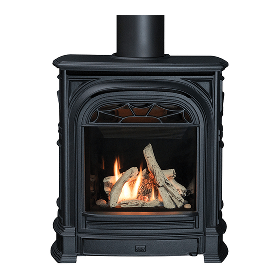
530 Direct Vent
GAS FIREPLACE HEATER
INSTALLATION BOOKLET
WARNING:
instructions is not followed exactly, a fire or
explosion may result causing property damage,
personal injury or loss of life.
- Do not store or use gasoline or other flammable
vapors and liquids in the vicinity of this or any
other appliance.
-WHAT TO DO IF YOU SMELL GAS
• Do not try to light any appliance.
• Do not touch any electrical switch: do not use
any phone in your building.
• Immediately call your gas supplier from a
neighbor's phone. Follow the gas supplier's
instructions.
• If you cannot reach your gas supplier, call the
fire department.
- Installation and service must be performed by a
qualified installer, service agency or the gas
supplier.
This appliance is a domestic room heating
appliance. It must not be used for any other
purpose such as drying clothes etc.
This appliance is suitable for installation in a
bedroom or bed sitting room.
MILES INDUSTRIES LTD.
Vous pouvez vous procurer un exemplaire en langue Française de cette
brochure chez votre marchand.
600B121-4
If
the
information
Manufactured by
British Columbia, Canada
in
these
Note: If this appliance is
intended to be installed with
a B-Vent instead of Direct
Vent, discard this manual.
Follow the installation and
operating procedure in the
manual supplied with the B-
Vent adapter kit #552BVK
• Safety Information
• Options
• Location
• Supply Gas
• Pack Contents
• Appliance
Preparation
• Installations with
different Models
• Installing to Wall
• Installations through
the roof
• Installing to Frame &
Fitting Heating Unit
• Fitting Sides and
Switch
• Gas Supply
Installation
• Aeration Setting
Check
• Ceramic Fuel Bed
Installation
• Window Refitting &
Checking
• Installation
Completion
Advertisement
Table of Contents

Related Manuals for Valor 530 Direct Vent


Summary of Contents for Valor 530 Direct Vent
-
Page 1: Safety Information
Note: If this appliance is 530 Direct Vent intended to be installed with a B-Vent instead of Direct GAS FIREPLACE HEATER Vent, discard this manual. Follow the installation and operating procedure in the INSTALLATION BOOKLET manual supplied with the B-... -
Page 2: Table Of Contents
8.12. Appliance Wall or Floor Fixing – President FS only .......................28 INSTALLATIONS WITH HORIZONTAL TERMINATION – INSTALLING TO WALL............29 9.1. Installations except with Valor #551DVK Terminal – Vent pipe fitting ................29 9.2. Making Wall Opening ................................29 9.3. Flat On Wall Installations With Valor #551DVK Terminal ....................29 9.4. -
Page 3: Safety Information
Children and adults should be alerted to the hazards accessible to any person. An approved Valor guard is of high surface temperatures and should stay away to available from your dealer. -
Page 4: Options
Black textured - Kit #531CSB. Kit# Black enameled – Kit #532ESB. 551DVK Valor terminal kit for non-combustible Green enameled – Kit #533ESG. wall thickness up to 26” (66cm) President ZC For zero clearance inset in framed (Combustible maximum 14” (36cm)) recess. - Page 5 Mantle depth “A” Min. Clearance“B” Up to 12” 4” Above 12” up to 18” 8” More than 18” 8”+extra 1” for every 1” depth above 18” Mantle leg Min clearance from projection “D” appliance side “E” Up to 8” 1” More than 8”...
-
Page 6: General
3. GENERAL 3.1. Approvals & codes This appliance is certified by International Approval Services for use in Canada and the USA. The appliance is for installation directly venting through an outside wall or through the roof. This appliance is supplied for use with natural gas. It can be converted for use with LP gas with Kit #554LPK. The appliance complies with CGA P.4.1, Testing method for measuring annual fireplace efficiencies. -
Page 7: Location - President Fs
Figure 4 President FS fixing holes 4.2. Venting configurations 4.2.1. Flat on wall Requires Valor vent kit #551DVK or Dura-vent pipe length with adapter #817VAK and Dura-vent terminal cap. The location requirements are shown in figure 5. The horizontal vent run can not be extended beyond the dimensions shown in figure 5 by the use of any vent accessory pipes. - Page 8 4.2.3. Rear vent connection, vertical vent rise with horizontal termination (Fig. 7) Can be used with either #551DVK standard vent kit or #984 Dura-vent terminal cap and accessories. Adapter #817VAK, two 90° vent elbows #990B and Dura-vent pipe lengths will be required. (See venting options section of this manual).
- Page 9 4.2.6. Corner location, rear vent connection, vertical rise, horizontal termination (Figs 7 & 9) Can be used with either #551DVK standard vent kit or #984 Dura-vent terminal cap and accessories. Adapter #817VAK, two 90° vent elbows #990B and Dura-vent pipe lengths will be required. (See venting options section of this manual).
- Page 10 4.2.9. Rear vent connection, installed to fireplace chimney with co-linear liners (Fig.12) Only for use when retro fitting a non-combustible fireplace and chimney. The appliance must not be connected to a chimney flue serving a separate solid-fuel burning appliance. Requires adapter #817VAK, Co- axial co-linear connector...
- Page 11 4.2.10. Top vent connection, vertical vent rise with horizontal rear termination (Fig.13) Can be used with either #551DVK standard vent kit or #984 Dura-vent terminal cap and accessories. Adapter #817VAK, one 90° vent elbow #990B and Dura-vent pipe lengths will be required. (See venting options section of this manual).
- Page 12 4.2.13. Top vent connection, corner location, vertical rise, horizontal termination, 45° pipe bend (Figs 13 & 15) Can be used with either #551DVK standard vent kit or #984 Dura-vent terminal cap and accessories. Adapter #817VAK, one 90° elbow #990B, one 45° elbow #945B and Dura-vent pipe lengths will be required.
- Page 13 4.2.16. Top vent connection, vertical vent rise with offset and through the roof termination (Fig.18) For situations where offset is necessary in an attic to avoid obstructions or allow useful space. Adapter #817VAK, two 45° vent elbows #984, wall straps, a vertical vent terminal, roof flashing and Dura-vent pipe lengths will be required.
-
Page 14: Location - President Zc And Impression Zc
5. LOCATION – PRESIDENT ZC and IMPRESSION ZC 5.1. Framing framing dimensions appliances with rear vent connection are shown in figure 19. framing dimensions appliances with top vent connection are shown in figure 20. The Zero clearance unit allows the front of the appliance surround to be positioned ", ¾”... -
Page 15: Venting Configurations
5.2. Venting configurations 5.2.1. Flat on wall (Fig. 22) Requires standard vent kit #551DVK only. The horizontal vent run can not be extended by the use of any vent accessory pipes. 5.2.2. Flat on wall with snorkel termination (Fig. 23) For use on horizontal vent installations where the outside ground level is too close to the standard terminal. - Page 16 Rear vent connection, vertical vent rise with horizontal termination (Fig. 24) Can be used with either #551DVK standard vent kit or #984 Dura-vent terminal cap and accessories. Adapter #817VAK, two 90° vent elbows #990B and Dura- vent pipe lengths will be required. (See venting options section of this manual).
- Page 17 5.2.6. Corner location, rear vent connection, vertical rise, horizontal termination (Figs 24 & 26) Can be used with either #551DVK standard vent kit or #984 Dura-vent terminal cap and accessories. Adapter #817VAK, two 90° vent elbows #990B and Dura-vent pipe lengths will be required.
- Page 18 5.2.9. Top vent connection, vertical vent rise with horizontal rear termination (Fig.29) Can be used with either #551DVK standard vent kit or #984 Dura-vent terminal cap and accessories. Adapter #817VAK, two 45° elbows #945B, one 90° vent elbow #990B and Dura-vent pipe lengths will be required. (See venting options section of this manual).
- Page 19 5.2.12. Top vent connection, corner location, vertical rise, horizontal termination, 45° pipe bend (Figs 29 & 31) Can be used with either #551DVK standard vent kit or #984 Dura-vent terminal cap and accessories. Adapter #817VAK, two 45° elbows #945B, one 90° vent elbow #990B and Dura-vent pipe lengths will be required.
- Page 20 5.2.14. Top vent connection, vertical vent rise with offset and through the roof termination (Fig.33) For situations where offset is necessary in an attic to avoid obstructions or allow useful space. Adapter #817VAK, four 45° vent elbows #984, wall straps, a vertical vent terminal, roof flashing and Dura- vent pipe lengths will be required.
-
Page 21: Vent Location
Vent location • The vent terminal must be located on an outside wall or through the roof. • This direct vent appliance is designed to operate when an undisturbed airflow hits the outside vent terminal from any direction. • The minimum clearances from this terminal that must be maintained when located on an outside wall are shown in figure 34. -
Page 22: Supply Gas
6. SUPPLY GAS All appliances are supplied for installation with natural gas. The supply pressure must be between the limits shown in section 3.2 of this manual. The supply connection is ’’NPT. The opening for the gas supply line is at the rear left corner of the appliance. 7. -
Page 23: Appliance Preparation
8. APPLIANCE PREPARATION 8.1. Detach the window Release the top of the window by pulling forward and rotating outwards the two bars at the top corners. See figure 35. Unscrew the two spring loaded bolts securing the bottom of the window. -
Page 24: Top Vent Outlet Positioning
8.4. Top Vent Outlet Positioning If installing with rear vent outlet go to next step. Remove the top plate and seal by unscrewing 12 screws. (See figure 38). Keep the seal, plate and screws for fitting to the back. Remove the rear outer vent collar and seal by unscrewing 12 screws (See figure 38). -
Page 25: Rear Vent Outlet Preparation
8.5. Rear Vent Outlet Preparation 8.5.1. For Installations With Dura-Vent DV GS Pipes If installing flat on wall with Valor terminal kit #551DVK, ignore this step : Fit the Dura-vent adapter #817VAK over the appliance vent collars pushing on firmly. -
Page 26: Attaching Stand-Off Spacers
Attaching Stand-Off Spacers 8.6.1. For President FS only These spacers need not be fitted if the rear of the appliance is more than 1 ” (32mm) from any combustible material and if the installer can be absolutely certain that no combustible construction will be added at a future date – consult with the owner. -
Page 27: Attaching Air Restrictors - Appliances With Vertical Vent Rise Only
8.7.3. Fit The Front Plinth Fit the front plinth under the appliance front with two thread forming screws – See figure 46. 8.8. Attaching Air Restrictors – Appliances with Vertical Vent Rise Only No restrictors are required for appliances, which only have a horizontal vent, run. There are three types of restrictor supplied with each #530 engine unit. -
Page 28: Attaching Top Air Deflector
8.9. Attaching top air deflector Fit the top air deflector under the top panel of the appliance case. Secure with two thread forming screws. See figure 49. Figure 49 8.10. Attaching Outer Surround - ZC Models Only Locate the surround over the appliance. Secure the surround to the sides of the appliance case with four thread cutting screws supplied. -
Page 29: Attaching Top Insulation Layers -Zc Models Only
Attaching Top Insulation Layers –ZC Models only For top vent outlet appliances cut out a circle at the center of the insulation layers for the vent collar. Place both the insulation layers on top of the appliance case inboard of the stand-off spacers. -
Page 30: Installations With Horizontal Termination - Installing To Wall
Dura-vent thimbles will not be required. With all the required Dura-vent pipes attached, slide the appliance into its correct location (If the Valor #551DVK terminal is being used, leave it off at this stage). If the wall has combustible material, mark the wall for a 10”x10” square hole if the wall. -
Page 31: Preparing Wall Plates
Figure 54 Figure 55 9.5. Installations except with Valor #551DVK Terminal – Installing to wall Unless the wall is totally non-combustible, fit Dura-vent wall thimbles #942. Slide the appliance into its correct position and install as detailed in the Duravent instructions supplied with the pipes. -
Page 32: Installations With Through The Roof Vertical Termination
10. INSTALLATIONS WITH THROUGH THE ROOF VERTICAL TERMINATION 10.1. All Co-axial Vent Installations Check the roof pitch to determine which roof flashing will be needed - see vent accessories section 2.4. The distance from the roof to the lowest terminal discharge opening (“H”... -
Page 33: Installing To Frame & Fitting Switch- Zc Appliances
11. INSTALLING TO FRAME & FITTING SWITCH– ZC APPLIANCES Secure the appliance to the framing by fixing to the studding through the bent tabs in the outer surround. Refit the burner module using the 11 screws previously removed (Figure 58). For appliance surround switch as only active switch •... - Page 34 For active remote control with active appliance switch Caution! Don’t connect the batteries in the remote control receiver until the wires are connected to the burner control unit. A short circuit could result in destruction of the electrical components. A set of four batteries and battery box is supplied with the appliance and a further set with the remote control unit.
-
Page 35: Fitting Sides & Switch - Fs Models
12. FITTING SIDES & SWITCH – FS MODELS For active appliance side switch as only active switch • Snap fit the switch into the opening in the switch mounting bracket.See figure 63 • Fit the two wire clips to the right side of the case. •... -
Page 36: Gas Supply Installation
13. GAS SUPPLY INSTALLATION The appliance is supplied for supply gas connection at the rear left corner of the case. An adapter is included in the pack that must be fitted to the appliance inlet pipe. Supply line connection to the adapter is ”NPT. -
Page 37: Aeration Setting Check
14. AERATION SETTING CHECK The burner is equipped with an adjustable shutter to control primary aeration. See figure 68. The shutter is factory set at an aeration gap which will give optimum performance for the vast majority of installations. In a few unusual installations performance may be improved by adjusting the aeration. -
Page 38: Ceramic Fuel Bed Installation
15. CERAMIC FUEL BED INSTALLATION 15.1. Ceramic Walls Installation Locate the ceramic rear wall in the channel at back of the firebox and flat against the back of the firebox. See figure 69. Locate the side walls in the channels at the sides of the firebox. See figure 70. Remove two screws from under the top front of the firebox. -
Page 39: Ceramic Logs Installation
15.2. Ceramic Logs Installation (See Section 15.3 for ceramic coals) Place the base log on the supports in the firebox and against the firebox back. See figure 72. Place the rear log over the base log. Locate the holes in the top log into the pegs in the base log. See figure 73. Place the front log behind the metal lip at front of the firebox. -
Page 40: Ceramic Coals Installation
15.3. Ceramic Coals Installation (See section 15.2 for ceramic logs) Place the base coal on the supports in the firebox and against the firebox back. See figure 77. Place the left front coal in position behind the metal lip at the front of the firebox. The side projection on this coal should be near the middle front of the firebox. -
Page 41: Window Refitting & Checking
16. WINDOW REFITTING & CHECKING Place the window centrally against the engine unit and resting on the support at bottom front of the engine. Pull the clamping bars forward and rotate inwards to secure the top of the window. See figure 82 Fit the two spring loaded bolts through the bottom of the window and tighten to secure the bottom of the window. -
Page 42: Operation Checks
17. OPERATION CHECKS 1. Check ignition, pilot stability , burner flames and the full range of the thermostat using the rotary switch inside the appliance and all other controls (appliance rocker switch, wall switch, remote hand unit). See owner’s lighting instructions further on in this manual for full details. -
Page 43: Installation Completion
18. INSTALLATION COMPLETION 18.1. President FS Hang the front casting by the hooks at the four corners as shown in figure 85. Fit the top casting making sure that the corners locate as shown in figure 86. If rear vent connection: Fit the top infill casting. See figure 87. If necessary the appliance can be leveled by the adjustment bolts at the back of the side castings. -
Page 44: President Zc
18.2. President ZC If tiling is to be applied right up to the sides of the front unit, the top of the front can be moved forward to allow the tiling to go behind the top. To move the top, slacken the clamping bolts, slide the top forward, retighten the bolts (See figure 89).
Need help?
Do you have a question about the 530 Direct Vent and is the answer not in the manual?
Questions and answers