Page 1
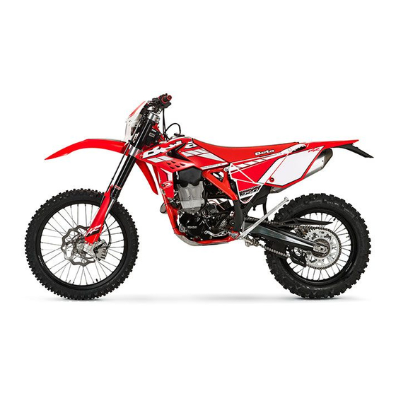
RR 350-390-430-480 EFI Thanks for you preference, and have a good time! This hand- book contains the information you need to properly operate and maintain your motorcycle. The data, specifications and images shown in this manual does not constitute an engagement on the part of BETAMOTOR S.p.A. BETAMOTOR reserves the right to make any changes and improvements to its models at any mo- ment and without notice.
Page 2
IMPORTANT We recommend you to check all the tightenings after the first one or two hours’ ride over rough ground. Special attention should be paid to the following parts: • rear sprocket • ensure that the footrests are properly fixed •...
OPERATING INSTRUCTIONS • The vehicle must be accompanied by: number-plate, registration document, tax disc and insurance. • Any modifications of the engine or other parts are punishable by severe sanctions including the confiscation of the vehicle. • To protect your safety and that of others, always drive carefully and with your helmet on and always keep low beams on.
RIDING SAFETY • Observe the Highway Code. • Always wear approved personal protective equipment. • Always ride with the low beam on. • Always keep the crash helmet visor clean. • Avoid wearing garments with hanging ends. • Do not keep sharp or brittle objects in your pockets while riding. •...
CHAPTER 1 GENERAL INFORMATION CONTENTS Vehicle identification data ............... 8 Frame identification ................8 Engine identification ................8 Tools kit ....................8 Familiarizing with the vehicle..............10 Main parts ..................10 Specifications ..................11 Weight ................... 11 Dimensions ..................11 Tyres ....................
VEHICLE IDENTIFICATION DATA FRAME IDENTIFICATION Frame identification data A are stamped on the right side of the steering head tube. ENGINE IDENTIFICATION Engine identification data B are stamped in the area shown in the figure. TOOLS KIT The following items are supplied as stand- ard: operation and maintenance manual, tool kit (see photo).
Page 9
To take the tool kit, remove the saddle 1 Pull the rear side panel 2 (page 76). Pull the rear side panel (page 77). Get off the male end wrenches (8 mm) and hexagon socket 3. With these is possible to unscrew the screw 4.
FAMILIARIZING WITH THE VEHICLE MAIN PARTS 10 - Lower bumper 1 - Fuel tank 18 - Front brake lever (Bumper kit) 2 - Tank cap 19 - Clutch lever 11 - Saddle 3 - Silencer 20 - Throttle 12 - Engine 4 - Rear shock absorber 21 - Fork covers 13 - Front mudguard...
SPECIFICATIONS WEIGHT Version Total [kg] Front [kg] Rear [kg] RR 350 - RR 390 111.5 54.5 RR 430 - RR 480 112.5 54.5 DIMENSIONS maximum length ................. 2180 mm maximum width ................807 mm overall height ................1270 mm wheelbase................. 1490 mm saddle height ................
Page 12
FRONT SUSPENSION Hydraulic upside-down fork (shafts Ø48 mm) with open cartridge Spring .................... K 4,8 Oil type ................SHELL TELLUS 32 Oil quantity (from the top, without spring and with fork compressed) .. 110 mm Compression clicks (from completely closed) ..........12 Rebound clicks (from completely closed) ..........
Page 13
ENGINE Version RR 350 RR 390 RR 430 RR 480 Type Single-cylinder, 4-stroke Bore x stroke [mm] 88x57,4 88x63,4 95x60,8 100x60,8 Displacement [cm³] 349,1 Compression ratio 13,19:1 12,5:1 12,3:1 11,9:1 Fuel system ..............electronic injection Cooling system ......... forced liquid circulation by pump Spark plug ..............
CHAPTER 2 OPERATION CONTENTS Main parts ..................16 Clutch lever ..................16 LH switch ..................16 Starter button .................. 16 Front brake lever and gas control ............17 Gear change lever................17 Brake pedal ..................17 Kickstart ..................17 Side stand ..................18 Keys ....................
MAIN PARTS CLUTCH LEVER Clutch lever 1 is fitted to the left-hand side of the handlebars. LH SWITCH The dip and service switch is located on the left side of the handlebar and is com- posed as follows: 1 - Horn button; 2 - Dip switch: only parking lights;...
FRONT BRAKE LEVER AND GAS CONTROL The front brake lever A and the gas throt- tle B are located on the right side of the handlebar. GEAR CHANGE LEVER Gear change lever is fitted to the left side of the engine. The positions corresponding to the different gears are shown in the figure.
SIDE STAND Press down side stand with the foot and lean the vehicle against it. Ensure that the ground is solid and the vehicle stands steadily. WARNING: do not climb on the vehicle when the side stand is down. If the vehicle is used off-road, the closed stand can be further fastened by means of rubber band.
KEYS The vehicle is supplied with two keys (one key and its spare). STEERING LOCK To activate the steering lock: - turn the handlebar counter-clockwise; - push the key and turn counter-clockwise; Remove the key from this position. To deactivate the steering lock: - turn the key clockwise;...
DIGITAL RPM INDICATOR OPERATING INSTRUCTIONS Contents 1 GENERAL SPECIFICATIONS AND GENERAL INFORMATIONS 1.1 General specifications 1.2 General informations 2 SETTING THE PARAMETERS 2.1 Setup sequence 2.1.1 Selecting the unit of measure 2.1.2 Selecting the wheel size 2.1.3 Selecting the clock format 2.1.4 Setting the Time 2.1.5 Selecting the maintenance memo 3 SCREENS...
Page 21
When using supplied power with the engine on: • The back-lighting is on permanently when the engine is running. Using only the internal battery: • With the LO symbol, the backlighting will not switch on. The symbol appears when the battery voltage is lower than 2.45V. Reset Button: Using the Reset button, located on the back of the instrument, all travel data will be deleted, including date and time.
Page 22
2.1 SETUP SEQUENCE Select unit of measure Wheel size Clock format Setting the Time Maintenance reminder 2.1.1 Selecting the unit of measure (Km/h or M/h): TO SELECT THE UNIT OF MEASURE (Km/h or M/h), PRESS THE RIGHT OR LEFT BUTTON. WAIT 5 SECONDS TO PROCEED TO THE NEXT SETTING.
Page 23
3 SCREENS Switching between 3 normal modes All of the information that the instrument is capable of providing is displayed on one of these 3 screens. The instrument will stay on the set screen until a button is pressed to switch to another screen.
Page 24
5 SPEEDOMETER Speed The speed is displayed in the centre of screens 1 or 2 and can range from 0 to 399.9 km/h or M/h. The unit of measure (km/h or M/h) appears next to the speed reading. Maximum (Max) and Average (AVG) speed The Maximum (MAX) or Average (AVG) speeds are displayed on screen 3 to the left of the display.
Page 25
Travelled distance (DST) The travelled distance can range from 0 to 9999.9 miles or kilometers and appears on the right side of screen 1. To clear the travelled distance, hold the right button down for 5 seconds. Note: you must be on screen 1 to clear the travelled distance. Travelled distance 2 (DST 2) Travelled distance 2 can range from 0 to 9999.9 miles or kilometers and appears on the right side of screen 2.
CHECKS BEFORE AND AFTER USE For safe driving and long vehicle life you should: 1 Check all fluid levels. 2 Check the correct operation of the brakes and brake pad wear (page 48). 3 Check pressure, general condition and thickness of tread. 4 Check that the spokes are properly tightened.
FUELLING Use unleaded petrol (gasoline). Disconnect the ventilation pipe 1. To open the tank turn the cap 2 anticlock- wise. To close the fuel tank’s cap, set it on the tank and crew it clockwise. Fuel tank capacity is shown on page 11. WARNING: The refuelling should be performed with the engine off.
STARTING THE ENGINE The bike starts ONLY with the battery mounted on the vehicle and connected to the electrical system. Check that the gears are in neutral (page 17). Close the side stand (page 18). WARNING: During start-up it is advisable not to operate the throttle. WHIT ELECTRIC STARTER (page 16): Push the button until the engine starts.
VEHICLE PREPARATION FOR USE IN HEAVY-DUTY CONDITIONS Using the vehicle in heavy-duty conditions, such as sand or wet or muddy soils, may require the corrective actions mentioned below. The following are considered heavy-duty operating conditions: Dry sand Wet sand Particularly wet and muddy soils Driving in high temperature and low speed conditions Driving in low temperature and snow conditions...
Page 30
USE ON PARTICULARLY WET AND MUDDY SOILS Apply an anti-water cap for the water filter Assemble a steel crown. For this operation contact the Betamotor service net- work. Verify that the radiator fins are clean Verify that the radiator fins are not bent After use, proceed with washing (page 67) DRIVING IN HIGH TEMPERATURE AND LOW SPEED CONDITIONS Adjust crown size based on the route.
CHAPTER 3 ADJUSTMENTS CONTENTS Key to symbols..................32 Brakes ....................32 Front brake ..................32 Rear brake ..................32 Clutch ....................32 Adjustment of gas clearance ..............33 Idle adjustment ..................33 Handlebar adjustment ................33 U-bolt position adjustment ..............33 Adjustment of the handlebar position ..........
KEY TO SYMBOLS Tightening torque Threadlocker Medium BRAKES FRONT BRAKE The front brake is disk type with hydraulic control. The home position of brake lever 2 can be adjusted by means of screw 1. REAR BRAKE The home position of brake pedal 3 can be altered by turning adjusting screw 5 af- ter loosening the counternut located under dust cap 4.
ADJUSTMENT OF GAS CLEARANCE The throttle control cable should always have a 3-5 mm play. In addition, the idle speed should not change when the han- dlebars are fully rotated to the left or right. Push back protective cap 1. Loosen coun- ternut 2 and turn adjusting screw 3.
To adjust the position of the u-bolt remove the screws shown in the figure. Remove the handlebar. Remove the screws 5. NOTE: Before removing the screws 5 heat the area with a hairdryer of the type used by coachbuilders. Position the U-bolt as required. At the end refit the screws 5 after the ap- 40Nm plication of thread lock fluid and tighten...
ADJUSTING FORK ADJUSTING THE REBOUND DAMPER The hydraulic rebound damper determines the behaviour of the telescopic fork during extension and can be adjusted by means of screw A. Turning the screw clockwise in- creases the action of the rebound damper; turning it anticlockwise decreases the ac- tion of the rebound damper.
ADJUSTING THE HYDRAULIC COMPRESSION DAMPER (HIGH AND LOW SPEEDS) Adjustment for low compression speed: •Using a screwdriver, loosen screw C by turning it clockwise to increase the hydraulic compression damper. For standard setting, refer to page 12. Adjustment for high compression speed: •Turn knob D anticlockwise to decrease the hydraulic compression damper.
STATIC SAG LOAD TEST To verify the static sag of the shock ab- sorber proceed as follows: - Place the motorcycle on the work stand. - Measure the vertical distance between the rear wheel axle and a reference point on the rear fairings. - Write down the dimension H - Remove the work stand.
SUSPENSIONS SETTINGS ACCORDING TO THE WEIGHT OF THE RIDER The table below shows the spring constant K of the suspensions (fork and shock absorber) depending on the weight of the driver. Refer to the accessories catalogue Betamotor to obtain the spring codes. Fork Rider weight [kg] K (Spring constant)
CHAPTER 4 CHECKS AND MAINTENANCE CONTENTS Engine oil ....................40 Check the level ..................40 Replacement ..................40 Gearbox oil ....................42 Check the level ..................42 Replacement ..................42 Liquid coolant ....................43 Check the level ..................43 Replacement ..................44 Air filter ....................45 Air filter cleaning...................46 Spark plug ....................47 Front brake....................48 Check the level of the front brake fluid .............48 Restoring the level of the front brake fluid ..........48...
ENGINE OIL CHECK THE LEVEL When engine is cold check the oil level by means of porthole 1. The oil level must be always visible from the porthole. In contrary case restore the oil level through cap 2 up to the upper edge of the inspec- tion window.
Page 41
To change the paper filter, remove the oil tap form engine unscrewing the two screws 3. Using special seeger ring pliers, pull the paper oil filter. Mount the new paper filter, close the oil tap to engine, tighten the screws at 10 Nm. Pour in the quantity of liquid indicated on page 11.
GEARBOX OIL CHECK THE LEVEL Hold the vehicle upright. Position the drive on a flat base ensuring stability. Remove the inspection cap 1. The oil level must arrive to the lower edge of check hole. In contrary case restore the oil level through cap 2.
Close plug 2. WARNING: Hot oil can cause severe burns! ATTENTION: Dispose of used oil in compliance with the regulations in force. Re-assemble the engine protection plate by tightening the screws to 10Nm. LIQUID COOLANT CHECK THE LEVEL Keep the vehicle in vertical position relative to the ground.
REPLACEMENT Keep the vehicle in vertical position relative to the ground. Replacement of the coolant must take place when the engine is cold. - Remove the engine casing by loosening the screws shown in the figure. - Unscrew cap 1. - Place a container under screw 2.
- Unscrew drain screw 3. - Proceed to filling. - Reapply the loading cap and the bleed- ing screw. The amounts of liquid are shown on page Use the liquid indicated on page 14 in the “Recommended lubricants and liquids” table. WARNING: Never unscrew the filler cap of the radiator when the engine is hot.
•Release filter fastener 1 •Pull out air filter 2 WARNING: After every intervention, check that nothing has been left inside the filter box. Reassemble by performing the operations in reverse order. AIR FILTER CLEANING • Thoroughly wash the filter with water and soap. •...
SPARK PLUG Keeping the spark plug in good condition will reduce fuel consumption and increase engine performance. To accede to spark plug, is necessary to take off saddle (page 76) and the fuel tank (page 76 78). Examine the distance between the elec- trodes with a feeler.
FRONT BRAKE CHECK THE LEVEL OF THE FRONT BRAKE FLUID Check the level of the brake fluid through sight A. The level of the fluid should never fall below the mark in the sight. RESTORING THE LEVEL OF THE FRONT BRAKE FLUID To restore the level of the brake fluid, loosen the two screws 1, lift cap 2 and add brake fluid until its level is 5 mm below the upper...
BLEEDING THE FRONT BRAKE To bleed air from the front brake circuit, proceed as follows: •Remove the rubber cap 1 from the valve 2. •Open the sump cap. •Place one end of a small transparent tube into the valve 2, and the other end inside a container.
FRONT BRAKE LINING CONTROL In order to verify the wear condition of front brake is enough to view the caliper from the bottom, where is possible to glimpse the brake lining tails which will have to show a brake of 2 mm in thickness. If the stratum is lesser let’s start replacing them.
REAR BRAKE CHECK THE LEVEL OF THE REAR BRAKE FLUID Check the level of the brake fluid through sight A. The level of the fluid should never fall below the mark in the sight. RESTORING THE LEVEL OF THE REAR BRAKE FLUID To restore the oil level, top up by means of oil filler cap 1.
BLEEDING THE REAR BRAKE To bleed air from the rear brake circuit, proceed as follows: •Remove the rubber cap 1 from the valve •Open the sump cap. •Place one end of a small transparent tube into the valve 2, and the other end inside a container.
FRONT BRAKE LINING CONTROL In order to verify the wear condition of front brake is enough to view the caliper from the bottom, where is possible to glimpse the brake lining tails which will have to show a brake of 2 mm in thickness. If the stratum is lesser let’s start replacing them.
CLUTCH CONTROL CHECK THE LEVEL To check the oil level in the clutch pump, first remove cover 2. Remove the two screws 1 and take off cover 2 together with the rubber bellows. With the clutch pump in a horizontal posi- tion, the level of the oil should be 5 mm below the upper rim.
BLEEDING To bleed air from the clutch pump, proceed as follows: •Remove the rubber cap 1 from the valve 2. •Open the sump cap. •Place one end of a small transparent tube into the valve 2, and the other end inside a container.
CHECK AND ADJUSTING OF STEERING PLAY Periodically check the play in the steering sleeve by moving the fork back and forth as shown in the figure. Whenever you feel play, adjust as described below: - Loosen the screws 1 - Loosen nut 2 20Nm - Reduce the play by turning nut 3 Tighten the screws to the prescribed torque...
OIL FORK The procedure for changing the oil in the forks is provided only for information. We recommend having the operation performed by a BETAMOTOR authorized workshop. REMOVING LEGS To replace, proceed as follows: • Position the vehicle on the central bike stand.
Page 58
• Loosen the counter-nut 2 and remove cap 1. • Extract the spring 3 and overturn the pipe, making the oil escape. • Move the pumping unit and drain the remaining oil. When the oil has been drained completely, introduce the amount of new oil described in chapter 1.
• Tighten the cap to the completely ex- tended leg. LEGS ASSEMBLY AND PARTS Apply the legs to the vehicle and tighten 17Nm the screws to the torque indicated. WARNING: grease the screws before their application. WARNING: Tightening of the screws should be carried out by adjusting the torque wrench to the stability torque with repeated tightening until stability...
Compress and release the fork 3-4 times. Tighten the wheel bolt and the screws of 50Nm the foot-leg. WARNING: Tightening of the screws should be carried out by adjusting the torque wrench to the stability torque with repeated tightening until stability torque has been achieved.
TYRES Only fit tyres approved by BETAMOTOR. Unsuitable tyres can adversely affect the road holding of the vehicle. • To protect your safety, immediately replace any damaged tyres. • Slick tyres adversely affect the road holding of the vehicle, especially on wet roads and in off-road riding. • Insufficient pressure results in abnormal wear and overheating of the tyres. • The front and rear tyres must have the same tread design. • Always measure the inflating pressures when the tyres are cold. • Keep the tyre pressures within the prescribed range. CHAIN Checking the drive chain periodically to ensure longer chain life. Always keep it lubricated and clean of deposited dirt.
• Loosen the pin 1. • Loosen counternuts A on either side of the fork. • Turn adjusting screws B on either side until the desired chain tension is obtained. • Tighten counternuts A on either side of the fork. •...
HEADLIGHT Keep the headlight glass clean at all times (see page 67). Periodically check the correct angle of the light beam. REPLACING THE HEADLIGHT BULBS Release both spring washers and move forward the lamp holder front cowl. Carefully remove the headlight bulb 1 together with lamp holder.
BATTERY Battery is located under the saddle and requires no maintenance. Keep the battery terminals clean. If neces- sary, protect them with a thin film of acid- free grease. BATTERY REMOVAL AND ASSEMBLY Remove the saddle (page 76). Release the rubber band. FIRST disconnect the negative connector (black) from negative (-) pole and THEN positive connector (black) from negative...
INACTIVITY If the vehicle is not going to be used for a long time, remove the battery and charge it every 15 days using a suitable charger. Store the battery in a dry place at a tem- perature of 5 to 35°C and out of the reach of children.
FUSES To access the fuse, remove the saddle (page 76). Fuse 1: in the event of a blown fuse, the services listed in the table are not opera- tional: Rear lights Stop Front lights Tachometer and control lights Turn lights Klaxon Electric fan (optional) Fuse 2: in the event of a blown fuse, the...
CLEANING THE VEHICLE GENERAL PRECAUTIONS WARNING: Do not clean your vehicle with a high-pressure device with a strong jet of water. Excessive pressure can reach electrical components, con- nectors, flexible cables, bearings, etc and can damage or destroy them. WARNING: Wash motorbikes frequently with cold water that are used near the sea (salty air) and on roads subject to salt spreading in winter.
To prevent malfunction of the electrical system, treat electric contacts and switches with electrical contact spray. ATTENTION: any oxidation of electrical contacts may result in serious malfunc- tioning to the power supply system. Specifically, treat the battery poles as described on page 64 and pay particular attention to what is contained here below.
2) rotate the safety device as shown; 3) remove the connector. For re-assembly, proceed opposite the above-mentioned order. AIR PRESSURE AND TEMPERATURE SENSOR Remove the tank (page 78). The connector is positioned as indicated in figure. 1) press the lock device; 2) Pull the connector upwards.
PROLONGED INACTIVITY A few simple operations should be performed to keep the vehicle in good condition whenever it is to remain inactive for a long period (e.g. during the winter): • Thoroughly clean the vehicle. • Reduce the tyre pressures by approximately 30 percent, and if possible raise the tyres off the ground.
SCHEDULED MAINTENANCE VEHICLE Engine Engine oil Paper filter oil Wire netting filter oil Gear and clutch oil Engine clamping screws Head screws Kick start and gearchange lever screws Spark plug cap Spark plug Breather pipe Countershaft bearings Crankshaft bearings Connecting rod Piston and segments Cylinder Surface appearance of the cams...
Page 72
Carburetor Tightness Idling setting Fuel pipe Breather pipe Assembling Coolant system tightness and coolant level groups Exhaust manifold tightness Drives sliding and regulation Liquid level clutch pump Airbox and air filter Chain, plate wheel and pinion Brake Liquid level, pads thickness Disc thickness Pipe tightness Idle travel levers and drives sliding...
TIGHTENING TORQUE OVERVIEW Here below is an overview of the tightening torque of all pieces subject to adjust- ment or maintenance: Forecarriage Tightening torque [Nm] Threadlock Wheel pin Fork foots - wheel pin Brake caliper - Fork U-bolt fork tube protection Steering head base - fork legs Steering head - fork legs Stem pin on steering head Lower handlebar u-bolt - steering head...
Page 74
Fairings Tightening torque [Nm] Notes Fuel tank to the frame (front fixing) Fuel tank to the frame (rear fixing) Grease Fuel tank fairings to the radiator...
CHAPTER 5 REMOVING AND INSTALLING SUPERSTRUCTURES CONTENTS Removing and installing of the saddle ............. 76 Removing and installing air filter cover panel ........... 77 Removing and installing of the tank ............78...
REMOVING AND INSTALLING OF THE SADDLE Press button 1. Remove the saddle towards the rear of the motorcycle. To re-assemble: Insert the cavity 1 of the saddle in slot 2. Press the saddle down in the middle and at the same time, push it forwards until the bayonet joint engages in its seat.
WARNING Make sure the bayonet joint 3 is firmly inserted into the button lock. REMOVING AND INSTALLING AIR FILTER COVER PANEL Remove the saddle (page 76). Grab the side panel in the front side and pull out. To refit insert the tabs 1 into their slots. Slide the side panel toward the vehicle.
REMOVING AND INSTALLING OF THE TANK Remove the saddle (page 76). Remove the two screws fastening the tank to the frame and the screw (one per side) securing the fairing to the radiator. Disconnect the fuel hose by pressing the appropriate button of the quick coupling.
TROUBLESHOOTING PROBLEM CAUSE REMEDY The engine starts but the Problem with the injection system Contact authorised BETAMOTOR light comes on “FI” customer service The electric starter does Decompressor failure Contact authorised BETAMOTOR not turn customer service Flat battery Check the battery Blown fuse Replace Defective relay...
ALPHABETICAL INDEX Adjusting fork ..................35 Adjustment of gas clearance ..............33 Air filter ....................45 Battery ....................64 Brakes ....................32 Chain ....................61 Check and adjusting of steering play ............56 Checks before and after use ..............26 Cleaning the vehicle ................
Page 82
Main parts ..................16 Oil fork ....................57 Operating instructions ................5 Prolonged inactivity ................70 Rear brake ..................51 Rear suspension leverage ..............60 Recommended lubricants and liquid ............14 Removing and installing air filter cover panel ........... 77 Removing and installing of the saddle .............
Need help?
Do you have a question about the RR 350 EFI and is the answer not in the manual?
Questions and answers