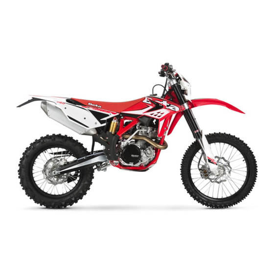
Beta RR 350 Owner's Manual
Hide thumbs Also See for RR 350:
Table of Contents

Advertisement

RR 350 - 400 - 450 - 498
Thanks for you preference, and have a good time! This hand-
book contains the information you need to properly operate and
maintain your motorcycle.
The data and specifi cations provided in this manual does not constitute an
engagement on the part of BETAMOTOR S.p.A. BETAMOTOR reserves the
right to make any changes and improvements to its models at any moment
and without notice.
GB
1

Advertisement

Table of Contents
loading

Summary of Contents for Beta RR 350

  • Page 1 RR 350 - 400 - 450 - 498 Thanks for you preference, and have a good time! This hand- book contains the information you need to properly operate and maintain your motorcycle. The data and specifi cations provided in this manual does not constitute an engagement on the part of BETAMOTOR S.p.A.
  • Page 2 • check that the plastics are properly fastened • engine bolts • shock absorber bolts/swingarm • wheel hubs/spokes • rear frame • pipe connections • tensioning the chain IMPORTANT For any servicing requirements, please get in contact with Beta- motor’s authorized service network.
  • Page 3: Table Of Contents

    CONTENTS Operating instructions ................5 Ecologic guide ..................5 Riding safety ..................6 CHAPTER 1 GENERAL INFORMATION ..........7 Vehicle identifi cation data ............... 8 Tools kit ....................8 Steering lock ..................10 Familiarizing with the vehicle..............11 Digital rpm indicator operating instructions ..........14 Specifi...
  • Page 4 CHAPTER 4 ADJUSTMENTS .............. 59 Adjusting the home position of the front brake lever........60 Adjusting the home position of the brake pedal ........60 Adjusting the home position of the clutch lever ......... 60 Adjusting the handlebars ..............60 Gas control adjustment .................
  • Page 5: Operating Instructions

    OPERATING INSTRUCTIONS • The vehicle must be accompanied by: number-plate, registration document, tax disc and insurance. • Do not carry animals, pets or loose objects that can stick out from the vehicle. • Riding without a crash helmet is forbidden. •...
  • Page 6: Riding Safety

    RIDING SAFETY • Observe the Highway Code. • Always put on and fasten a homologated helmet. • Always ride with the low beam on. • Always keep the crash helmet visor clean. • Avoid wearing garments with hanging ends. • Do not keep sharp or brittle objects in your pockets while riding. •...
  • Page 7: Chapter 1 General Information

    CHAPTER 1 GENERAL INFORMATION CONTENTS Vehicle identifi cation data ............... 8 Frame identifi cation ................8 Engine identifi cation ................8 Tools kit ....................8 Steering lock ..................10 Familiarizing with the vehicle..............11 Main parts: ..................11 Clutch lever ..................12 Front brake lever ................
  • Page 8: Vehicle Identifi Cation Data

    VEHICLE IDENTIFICATION DATA FRAME IDENTIFICATION Frame identifi cation data A are stamped on the right side of the steering head tube. ENGINE IDENTIFICATION Engine identifi cation data B are stamped in the area shown in the fi gure. WARNING: Tampering with the identifi cation numbers is severely punished by law.
  • Page 9 To take the tool kit, push the button 1 to get off the saddle. Pull back the saddle. Pull the rear side panel 2 to disassemble it. Get off the male end wrenches and hexa- gon socket 3. With these is possible to unscrew the screw 4.
  • Page 10: Steering Lock

    STEERING LOCK The vehicle is supplied with one key and a spare to be used for the steering lock. WARNING: Do not keep the spare keys in the vehicle. Keep the keys in a safe and easy-to-reach place. The code number stamped on the keys should be copied on this manual (or elsewhere) so it can be used to ask for duplicates should both keys be lost.
  • Page 11: Familiarizing With The Vehicle

    FAMILIARIZING WITH THE VEHICLE MAIN PARTS: 10 - Lower bumper 18 - Fork covers 1 - Fuel tank 19 - Rear mudguard (Bumper kit) 2 - Tank cap 11 - Saddle 20 - Cover air fi lter 3 - Silencer 12 - Engine 4 - Rear shock absorber 13 - Front mudguard...
  • Page 12: Clutch Lever

    CLUTCH LEVER Clutch lever 1 is fi tted to the left-hand side of the handlebars. Screw A can be used to alter the home position of the lever (see Adjustments). FRONT BRAKE LEVER Front brake lever 2 is fi tted to the right-hand side of the handlebars.
  • Page 13: Starter Button

    STARTER BUTTON Starter button 1 is located on the right- hand side of the handlebars and operate the electric engine starter. Push the button until the engine starts. Do not press the button 1 while the engine is running. LH SWITCH Dip switch 2 has three positions: A = lights off B = low beam on...
  • Page 14: Digital Rpm Indicator Operating Instructions

    DIGITAL RPM INDICATOR OPERATING INSTRUCTIONS GENERAL SPECIFICATIONS SPEED/DISTANCE SENSOR: Non-contact magnetic SCREEN MEASUREMENTS: 125mm x 41mm x 34mm STORAGE TEMPERATURE: -20°C to 80°C (-4°F to 176°F) BATTERY: 3V CR2032 BATTERY LIFE: Approximately one year EXTERNAL CURRENT SUPPLY: 12V DC GENERAL INFORMATION Backlight: The digital speedometer/odometer is backlit to enable reading where there is poor or no lighting.
  • Page 15 SETTING THE PARAMETERS General information: Allowed settings: • Km/h (kilometres per hour) or M/h (Miles per hour) • Wheel size (rolling circumference) [mm] • Clock format: 12-hour / 24-hour • Current date • Maintenance TO ENTER THE PARAMETER SETTINGS MODE HOLD DOWN THE RIGHT AND LEFT BUTTONS FOR APPROX.
  • Page 16 Selecting the unit of measure (Km/h or M/h): TO SELECT THE UNIT OF MEASURE (Km/h or M/h), PRESS THE RIGHT OR LEFT BUTTON. WAIT 5 SECONDS TO PROCEED TO THE NEXT SETTING. DO NOT PRESS ANY BUTTONS. Selecting the wheel size (rolling circumference): The instrument has programmed two rolling circumference measurements for the front wheel: 2190mm (Enduro version - 21”...
  • Page 17 SCREENS Switching between 3 normal modes All of the information that the instrument is capable of providing is displayed on one of these 3 screens. The instrument will stay on the set screen until a button is pressed to switch to another screen.
  • Page 18 SPEEDOMETER Speed The speed is displayed in the centre of screens 1 or 2 and can range from 0 to 399.9 km/h or M/h. The unit of measure (km/h or M/h) appears next to the speed reading. Maximum (Max) and Average (AVG) speed The Maximum (MAX) or Average (AVG) speeds are displayed on screen 3 to the left of the display.
  • Page 19 Travelled distance (DST) The travelled distance can range from 0 to 9999.9 miles or kilometers and appears on the right side of screen 1. To clear the travelled distance, hold the right button down for 5 seconds. Note: you must be on screen 1 to clear the travelled distance. Travelled distance 2 (DST 2) Travelled distance 2 can range from 0 to 9999.9 miles or kilometers and appears on the right side of screen 2.
  • Page 20: Specifi Cations

    SPECIFICATIONS WEIGHT Dry weight RR 350 - 400 ......113 kg (front 55 Kg; rear 58 Kg) Dry weight RR 450 - 498 ....113,5 kg (front 55 Kg; rear 58,5 Kg) DIMENSIONS maximum length ................. 2180 mm maximum width ................807 mm overall height ................
  • Page 21: Front Suspension

    FRONT SUSPENSION “SACHS” hydraulic upside-down fork (Ø48 mm shafts) spring ..................... K 4,8 oil type ................SHELL TELLUS 32 oil quantity (from the top, without spring and with fork compressed) ... 110 mm REAR SUSPENSION Single shock absorber with compound lever spring .....................
  • Page 22: Engine

    Type ..........Single cylinder, 4-stroke, liquid-cooled with countershaft and electric starting Bore x stroke RR 350 ............88 x 57,4 mm Bore x stroke RR 400 ............95 x 56,2 mm Bore x stroke RR 450 ............95 x 63,4 mm Bore x stroke RR 498 ............
  • Page 23 Lubrication ................2 oil pumps Cooling system ......... forced liquid circulation by pump Spark plug ..............NGK LKAR 8A - 9 Clutch .................. wet, multidisc Transmission ..........6-speed with front claw clutch Version RR 350 RR 400 RR 450 RR 498 Primary drive 28/76...
  • Page 24: Electrical System

    ELECTRICAL SYSTEM ELECTRICAL DIAGRAM RR 4T...
  • Page 25: Legend Electrical Diagram

    LEGEND ELECTRICAL DIAGRAM RIGHT-HAND FRONT TURN INDICATOR (12V-10W BULB) FRONT BRAKE LIGHT BUTTON START BUTTON WHEEL REVOLUTION SENSOR TRAFFICATOR LIGHTS TELL TALE LAMP RIGHT BUTTON DISPLAY LEFT BUTTON HEADLIGHT TELL TALE LAMP HEADLIGHT (12V-35/35W BULB) 12V HORN ENGINE STOP BUTTON HORN BUTTON HEADLIGHT SELECTOR TURN SIGNAL LAMPS SWITCH...
  • Page 26: Battery

    BATTERY Battery 1 is located under the saddle and requires no maintenance. It is not necessary to check the level of the electrolyte or top up with water. Keep the battery terminals clean and, if necessary, protect them with a small quantity of vaseline technique.
  • Page 27: Fuse

    FUSE Fuse 3 is located in starting relay 4 placed under the saddle and front the battery. To gain access to the fuse remove the saddle. The fuse protects the following devices: •electric starter •horn •indicators •instrument panel The starting relay also contains spare fuse 5 (10 amperes).
  • Page 28: Recommended Lubricants And Liquid

    RECOMMENDED LUBRICANTS AND LIQUID To maximize the vehicle’s performance and ensure many years of trouble-free opera- tion, we recommend using the following products: PRODUCT TYPE SPECIFICATIONS ENGINE OIL PANOLIN OFF ROAD 4T RACE 10W/50 GEAR AND CLUTCH OIL PANOLIN OFF ROAD 4T SYNTH 10W/40 BRAKE OIL DOT 4 CLUTCH ACTUATOR OIL...
  • Page 29: Chapter 2 Operation

    CHAPTER 2 OPERATION CONTENTS Checks to be performed before each ride ..........30 Running-in ................... 31 Engine start ..................32 Cold starting ................... 32 Hot starting ..................32 What to do if the engine is “fl ooded” ..........32 Refuelling .................... 33 Fuel tank cap ..................
  • Page 30: Checks To Be Performed Before Each Ride

    CHECKS TO BE PERFORMED BEFORE EACH RIDE The vehicle can be used only if it is in perfect condition from a technical point of view. To ensure maximum safety, it is advisable to carry out a general inspection of the motorcycle before each ride. The checks to be performed are described below. 1 CHECK THE ENGINE OIL LEVEL Insuffi...
  • Page 31: Running-In

    RUNNING-IN The running-in period lasts approximately 15 hours, during which it is advisable to: 1 During the fi rst 3 hours of operation the engine should only be used to approxi- mately 50 percent of its power. In addition, the engine speed should not exceed 7,000 rpm.
  • Page 32: Engine Start

    ENGINE START COLD STARTING 1 Open fuel cock 1. 2 Take the vehicle off the stand. 3 Shift into neutral. 4 Operate choke 2 by pulling it until it stops. 5 WITHOUT opening the throttle, fi rmly and FULLY operate kickstart 3 or use the electric starter.
  • Page 33: Refuelling

    REFUELLING FUEL TANK CAP Open: Turn tank cap 1 anticlockwise. Close: Replace the tank cap and turn it clockwise. Arrange tank breather pipe 2 so that it forms no kinks. FUEL TAP OFF Fuel cock 3 is closed. ON Before using the vehicle, turn the knob to ON.
  • Page 35: Chapter 3 Checks And Maintenance

    CHAPTER 3 CHECKS AND MAINTENANCE CONTENTS Oil circuit .................... 36 Checking the engine oil level ............36 Changing the engine oil and fi lters extraction ........37 Changing the gear and clutch oil ............39 Brakes ....................40 Check the level of the front brake fl uid ..........40 Restoring the level of the front brake fl...
  • Page 36: Oil Circuit

    OIL CIRCUIT The pump 1 (high pressure) push oil to crank mechanism 4, to piston oil jet 5, to stretcher 6, to head jet 7. The valve 2 control the pressure and the paper fi lter 3 scrubs the oil from subtle impurity. When oil has lubricated the head and has pushed the chain stretcher, the oil goes in generator room A.
  • Page 37: Changing The Engine Oil And Fi Lters Extraction

    CHANGING THE ENGINE OIL AND FILTERS EXTRACTION Before performing this operation, remove the lower bumper A, after underscrewing the three screws B as shown in the fi gure. Whenever the oil is changed, is necessary to change the paper fi lter and to clean the wire netting fi...
  • Page 38 To change the paper fi lter, remove the oil tap form engine unscrewing the two screws E. Using special seeger ring pliers, pull the paper oil fi lter. Mount the new paper fi lter, close the oil tap to engine, tighten the screws at 6 Nm. Remove screw fastener from left carter and pour in 800 ml engine oil PANOLIN OFF ROAD 4T RACE 10W/50.
  • Page 39: Changing The Gear And Clutch Oil

    CHANGING THE GEAR AND CLUTCH OIL Before performing this operation, remove the lower bumper A after unscrewing the three screws B as shown in the picture. The oil must be changed when the engine is at operating temperature. Park the motorcycle on level ground, remove the screw C and let oil drain in a container.
  • Page 40: Brakes

    BRAKES CHECK THE LEVEL OF THE FRONT BRAKE FLUID Check the level of the brake fl uid through sight A. The level of the fl uid should never fall below the mark in the sight. RESTORING THE LEVEL OF THE FRONT BRAKE FLUID To restore the level of the brake fl...
  • Page 41: Check The Level Of The Rear Brake Fl Uid

    CHECK THE LEVEL OF THE REAR BRAKE FLUID Check the level of the brake fl uid through sight D. The level of the fl uid should never fall below the mark in the sight. RESTORING THE LEVEL OF THE REAR BRAKE FLUID To restore the level of the brake fl...
  • Page 42: Front Brake Lining Control

    FRONT BRAKE LINING CONTROL In order to verify the wear condition of front brake is enough to view the pincer from the bottom, where is possible to glimpse the brake lining tails which will have to show a brake of 2 mm in thickness. If the stratum is lesser let’s start replacing them.
  • Page 43: Tyres

    TYRES Only fi t tyres approved by BETAMOTOR. Unsuitable tyres can adversely affect the road holding of the vehicle. • To protect your safety, immediately re- place any damaged tyres. • Slick tyres adversely affect the road holding of the vehicle, especially on wet roads and in off-road riding.
  • Page 44: Hydraulic Clutch

    HYDRAULIC CLUTCH CHECK OIL LEVEL To check the oil level in the clutch pump, fi rst remove cover 2. Remove the two screws 1 and take off cover 2 together with the rubber bellows. With the clutch pump in a horizontal posi- tion, the level of the oil should be 5 mm below the upper rim.
  • Page 45: Fork Oil

    FORK OIL Right/left-hand rod The procedure for changing the oil in the forks is provided only for information. We recommend having the operation performed by a BETAMOTOR authorized workshop. • Rest the motor on a central stand, lift it making sure that it is stable. •...
  • Page 46 • Loosen the counter-nut 2 and remove cap 1. • Extract the spring 3 and overturn the pipe, making the oil escape. • Move the pumping unit and drain the remaining oil. When the oil has been drained completely, introduce the amount of new oil described in chapter 1.
  • Page 47 • Tighten the cap to the completely ex- tended leg. • Insert the legs into the plates. Once the leg has been positioned at the desired extension, tighten screws E at 17Nm and F at 12Nm, after the screws have been greased.
  • Page 48: Air Filter

    AIR FILTER A dirty air fi lter hinders the passage of air, reduces engine power and increases fuel consumption. For these reasons it is essen- tial to clean the air fi lter on a regular basis. Follow these steps to gain access to the air fi...
  • Page 49: Spark Plug

    SPARK PLUG To accede to spark plug, is necessary to take off saddle and the fuel tank. To remove the fuel tank proceed as follows. Unscrew the two screws A, unscrew the screw B (both side). Close the fuel tap (OFF position) and disconnect the pipe fuel C from the fuel tap.
  • Page 50 Measure the spark gap with a thickness gauge. The gap should be 0.8÷0.9 mm. If the gap is not as specifi ed, restore the proper gap by bending the earth elec- trode. Check that the insulator is not cracked and that the electrodes are not corroded, in which case the spark plug should be immediately replaced.
  • Page 51: Carburettor

    CARBURETTOR CARBURETTOR WEAR GUIDELINES The throttle valve, the needle valve and the needle jet are subject to heavy wear due to engine vibrations. This can result in carburettor malfunctions (e.g. mixture enrichment). DRAINING THE CARBURETTOR FLOAT CHAMBER The carburettor float chamber can be drained by following the procedure de- scribed below while the engine is cold.
  • Page 52: Coolant

    CHECKING THE FLOAT LEVEL (FLOAT HEIGHT) Remove the carburettor and the float chamber. Tilt the carburettor so that the fl oat touches the fl oat needle valve without pressing it too hard. In this position the fl oat edge should be parallel with the fl...
  • Page 53: Chain

    CHAIN DRIVE CHAIN MAINTENANCE The life of the drive chain largely depends on its maintenance. Chains without X- rings must be periodically cleaned in petroleum and then immersed in hot chain oil or treated with a chain spray. X-ring chains require very little maintenance. The best way to clean them is rinsing them generously with water.
  • Page 54: Battery

    BATTERY CHARGING THE BATTERY Remove the battery and check its charge. Using an open-circuit multimeter (10-12 hours after the activation), check that the voltage is greater than 12.6 V. If it is lower, it is advisable to recharge the battery. Based on the type of charger available, charge the battery using either of the fol- lowing procedures:...
  • Page 55: Cleaning The Vehicle

    CLEANING THE VEHICLE WARNING: Do not clean your vehicle with a high-pressure device with a strong jet of water. Excessive pressure can reach electrical components, connectors, fl exible cables, bearings, etc and can damage or destroy them. WARNING: Wash motorbikes frequently that are used near the sea (salty air) and on roads subject to salt spreading in winter.
  • Page 56: Scheduled Maintenance Vehicle

    SCHEDULED MAINTENANCE VEHICLE Engine Engine oil Paper fi lter oil Wire netting fi lter oil Gear and clutch oil Engine clamping screws Kick start and gearchange lever screws Spark plug cap Spark plug Breather pipe Countershaft bearings Crankshaft bearings Connecting rod Piston and segments Cylinder Surface appearance of the cams...
  • Page 57 Carburetor Tightness Idling setting Fuel pipe Breather pipe Assembling Coolant system tightness and coolant level groups Exhaust manifold tightness Drives sliding and regulation Liquid level clutch pump Airbox and air fi lter Chain, plate wheel and pinion Brake Liquid level, pads thickness Disc thickness Pipe tightness Idle travel levers and drives sliding...
  • Page 58: Prolonged Inactivity

    PROLONGED INACTIVITY A few simple operations should be performed to keep the vehicle in good condition whenever it is to remain inactive for a long period (e.g. during the winter): • Thoroughly clean the vehicle. • Reduce the tyre pressures by approximately 30 percent, and if possible raise the tyres off the ground.
  • Page 59: Chapter 4 Adjustments

    CHAPTER 4 ADJUSTMENTS CONTENTS Adjusting the home position of the front brake lever........60 Adjusting the home position of the brake pedal ........60 Adjusting the home position of the clutch lever ......... 60 Adjusting the handlebars ..............60 Gas control adjustment ................. 61 Checking and adjusting the steering play ..........
  • Page 60: Adjusting The Home Position Of The Front Brake Lever

    ADJUSTING THE HOME POSITION OF THE FRONT BRAKE LEVER The home position of brake lever 2 can be adjusted by means of screw 1. ADJUSTING THE HOME POSITION OF THE BRAKE PEDAL The home position of brake pedal 3 can be altered by turning adjusting screw 5 af- ter loosening the counternut located under dust cap 4.
  • Page 61: Gas Control Adjustment

    GAS CONTROL ADJUSTMENT The throttle control cable should always have a 3-5 mm play. In addition, the idle speed should not change when the handle- bars are fully rotated to the left or right. Push back protective cap 10. Loosen counternut 11 and turn adjusting screw 12.
  • Page 62: Adjusting Fork

    ADJUSTING FORK ADJUSTING THE REBOUND DAMPER The hydraulic rebound damper determines the behaviour of the telescopic fork during extension and can be adjusted by means of screw A. Turning the screw clockwise (towards the + sign) increases the action of the rebound damper; turning it anticlock- wise (towards the –...
  • Page 63: Shock Absorber

    SHOCK ABSORBER ADJUSTING THE HYDRAULIC COMPRESSION DAMPER (HIGH AND LOW SPEEDS) The shock absorber can be adjusted for both high and low speeds. The terms ‘high’ and ‘low’ refer to the compression speed of the shock absorber, not to the speed of the vehicle.
  • Page 64: Adjusting The Hydraulic Rebound Damper

    ADJUSTING THE HYDRAULIC REBOUND DAMPER Turn screw G to adjust the hydraulic re- bound damper. Turning the screw anticlockwise (out) de- creases the damping effect. Standard adjustment RR 2t: clicks from the completely closed position TENSIONING THE CHAIN To ensure the drive chain a longer life, it is advisable to periodically check its tension.
  • Page 65: Adjusting The Idle Speed

    ADJUSTING THE IDLE SPEED Engine starting is strongly affected by the idle speed adjustment. In other words, an engine whose slow running is properly adjusted is easier to start than an engine with an unsuitably tuned up engine. The idle speed is adjusted by means of adjusting knob 1 and mixture adjusting screw 2.
  • Page 66 NOTE Failure to successfully complete the above procedure can be the result of an improp- erly sized idling jet. a) If the mixture adjusting screw is turned until it stops and no changes in the idle speed are observed, a smaller idling jet is required. b) If the engine stalls when the adjusting screw is still two turns open, a larger idling jet is needed.
  • Page 67: Chapter 5 Replacements

    CHAPTER 5 REPLACEMENTS CONTENTS Replacing the brake pads ..............68 Front ....................68 Rear....................69 Replacing the headlight bulbs ..............70 Tail light ....................70...
  • Page 68: Replacing The Brake Pads

    REPLACING THE BRAKE PADS The procedure for replacing the brake pads is provided only for information. We recommend having the operation performed by a BETAMOTOR authorized workshop. FRONT Follow these steps to replace the pads: •Push the brake caliper towards the disc so that the pistons reach their home positions.
  • Page 69: Rear

    REAR Follow these steps to replace the pads: •Push the brake caliper towards the disc so that the pistons reach their home positions. •Unscrew dowel A. •Pull out pin B, while supporting the two pads as shown in the fi gure. •Remove the brake pads taking care not to drop the leaf spring located above the two pads.
  • Page 70: Replacing The Headlight Bulbs

    REPLACING THE HEADLIGHT BULBS Release both spring washers and move forward the lamp holder front cowl. Carefully remove the headlight bulb 1 together with lamp holder. To replace the high beam / low beam, lift the rubber cover 2, release connector, push on the spring 3 and remove the lamp holder and replace the light bulb with a new one.
  • Page 71: Chapter 6 Troubleshooting

    CHAPTER 6 TROUBLESHOOTING CONTENTS Troubleshooting ................... 72 Alphabetical index ................73...
  • Page 72: Troubleshooting

    - Air fi lter dirty. Proceed as described on page 48 - No current supplied to spark plug. Clean or replace the spark plug. If the problem persists, contact a BETA- MOTOR dealer. - Engine fl ooded. Operate the start-up pedal 5-10 times or the electrical starter pushbutton 2 times every 5 seconds.
  • Page 73: Adjusting The Home Position Of The Brake Pedal

    ALPHABETICAL INDEX Adjusting fork ..................62 Adjusting the handlebars ..............60 Adjusting the home position of the brake pedal ........60 Adjusting the home position of the clutch lever ......... 60 Adjusting the home position of the front brake lever........60 Adjusting the idle speed ................
  • Page 74 Recommended lubricants and liquid ............28 Refuelling .................... 33 Replacing the brake pads ..............68 Replacing the headlight bulbs ..............70 Riding safety ..................6 Running-in ................... 31 Scheduled maintenance vehicle ............. 56 Shock absorber..................63 Spark plug ..................49 Specifi...

This manual is also suitable for:

Rs 4t 390Rs 4t 430Rs 4t 500Rr 498

Table of Contents