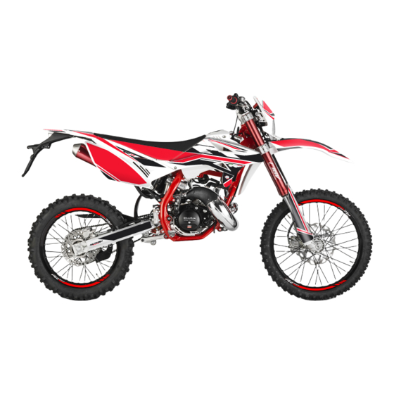
Beta RR 50 CC ENDURO Operating Instructions Manual

Beta RR 50 CC ENDURO Operating Instructions Manual

Hide thumbs Also See for RR 50 CC ENDURO:
Table of Contents

Advertisement

RR 50 CC ENDURO / ENDURO SPORT / FACTORY /
MOTARD / MOTARD SPORT / TRACK
Thanks for you preference, and have a good time! This hand-
book contains the information you need to properly operate and
maintain your motorcycle.
The data and specifications provided in this manual does not constitute an
engagement on the part of BETAMOTOR S.p.A. BETAMOTOR reserves the
right to make any changes and improvements to its models at any moment
and without notice.
Code 024440080 000
GB
1

Advertisement

Table of Contents
loading

Summary of Contents for Beta RR 50 CC ENDURO

  • Page 1 RR 50 CC ENDURO / ENDURO SPORT / FACTORY / MOTARD / MOTARD SPORT / TRACK Thanks for you preference, and have a good time! This hand- book contains the information you need to properly operate and maintain your motorcycle.
  • Page 2 • check that the plastics are properly fastened • engine bolts • shock absorber bolts/swingarm • wheel hubs/spokes • rear frame • pipe connections • tensioning the chain IMPORTANT For any servicing requirements, please get in contact with Beta- motor’s authorized service network.
  • Page 3: Table Of Contents

    CONTENTS Operatings instructions ................5 Symbols ....................5 Riding safety ..................6 CHAPTER 1 GENERAL INFORMATION ..........7 Vehicle identification data ............... 8 Technical data ..................10 Electrical system ................... 14 Recommended lubricants and liquids ............16 CHAPTER 2 OPERATION ..............17 Main parts ..................
  • Page 4 Air filter ....................45 Spark plug ..................46 Carburettor ..................47 Tyres....................48 Check and adjusting of steering play ............48 Chain ....................49 Headlight .................... 50 Replacing the headlight bulbs ..............50 Tail light ....................50 Cleaning the vehicle ................51 Prolonged inactivity ................
  • Page 5: Operatings Instructions

    OPERATINGS INSTRUCTIONS • The vehicle must be accompanied by: number-plate, registration document, tax disc and insurance. • Any modifications of the engine or other parts are punishable by severe sanctions including the confiscation of the vehicle. • To protect your safety and that of others, always drive carefully and with your helmet on and always keep low beams on.
  • Page 6: Riding Safety

    RIDING SAFETY • Observe the Highway Code. • Always wear approved personal protective equipment. • Always ride with the low beam on. • Always keep the crash helmet visor clean. • Avoid wearing garments with hanging ends. • Do not keep sharp or brittle objects in your pockets while riding. •...
  • Page 7: Chapter 1 General Information

    CHAPTER 1 GENERAL INFORMATION CONTENTS Vehicle identification data ............... 8 Frame identification ................8 Engine identification ................8 Familiarizing with the vehicle .............. 9 Main parts ..................9 Technical data ..................10 Vehicle dimensions ................10 Tyres ....................10 Filling capacity ................11 Front suspension ................
  • Page 8: Vehicle Identification Data

    VEHICLE IDENTIFICATION DATA FRAME IDENTIFICATION Frame identification data A are stamped on the right side of the steering head tube. ENGINE IDENTIFICATION Engine identification data B are stamped on the l.h. side half crankcase. WARNING: Tampering with the identification numbers is severely punished by law.
  • Page 9: Familiarizing With The Vehicle

    FAMILIARIZING WITH THE VEHICLE MAIN PARTS 1 - Fuel tank 10 - Kickstarter 18 - Fork covers 2 - Tank cap 11 - Saddle 19 - Rear mudguard 3 - Silencer 12 - Engine 4 - Rear shock absorber 13 - Front mudguard 5 - Headlight 14 - Number-plate holder 6 - Rear light...
  • Page 10: Technical Data

    TECHNICAL DATA dry weight (all models) ..............85 kg VEHICLE DIMENSIONS Version ENDURO MOTARD FACTORY ENDURO MOTARD SPORT SPORT / TRACK Maximum 2085 2000 2085 2052 2000 length [mm] Maximum width [mm] Maximum height 1225 1155 1225 1190 1155 from ground [mm] Clearance from ground [mm] Saddle height [mm]...
  • Page 11: Filling Capacity

    MOTARD SPORT / MOTARD / TRACK Front tyre Rear tyre Dimension Pressure [Bar] Dimension Pressure [Bar] 100/80 - 17 or 130/70 - 17 or 100/80-17 TL 130/70-17 TL FILLING CAPACITY fuel tank ..................6 liters including reserve of ................1 liter cooling circuit liquid All the models ................
  • Page 12: Rear Suspension

    REAR SUSPENSION Version ENDURO / MOTARD SPORT / FACOTRY ENDURO MOTARD / TRACK SPORT spring (k) [Kg/mm] 12,5 Length (spring in its seat) [mm] Click in compression (from fully closed) Click in extension (from fully closed) FRONT BRAKE disk-type with hydraulic control Ø 260 mm REAR BRAKE disk-type with hydraulic control Ø...
  • Page 13: Fuel System

    FUEL SYSTEM Version Homologated Competition* Carburetor type DELL’ORTO PHBN 16 HS Main jet Slow jet Start jet Needle Needle position 2° 2° (from top) Air screw turns 1+1/2 1+1/2 (from fully closed) * - Such modification makes the vehicle non-compliant with the road regulations in force.
  • Page 14: Electrical System

    ELECTRICAL SYSTEM ELECTRICAL DIAGRAM...
  • Page 15: Legend Electrical Diagram

    LEGEND ELECTRICAL DIAGRAM KEY SWITCH OIL PILOT LAMP NEUTRAL INDICATOR LIGHT HIGH BEAM WARNING LIGHT DIRECTION INDICATOR WARNING LIGHT WHEEL REVOLUTION SENSOR HEADLAMP (DOUBLE FILAMENT BULB) SIDE/TAILLIGHT BULB 12V - 5W ENGINE STOP BUTTON HORN BUTTON HEADLIGHT SELECTOR TURN SIGNAL LAMPS SWITCH L.H.
  • Page 16: Recommended Lubricants And Liquids

    RECOMMENDED LUBRICANTS AND LIQUIDS For better operation and longer vehicle life, we advise you to use the products listed in the following chart: TYPE OF PRODUCT TECHNICAL SPECIFICATION GEAR AND CLUTCH OIL LIQUI MOLY RACING 4T 10W-30 OIL MIXTURE LIQUI MOLY 2-STROKE MOTOR OIL, SELF-MIXING LIQUI MOLY RACING SYNTH 2T (Enduro - Factory) BRAKE OIL DOT 4...
  • Page 17: Chapter 2 Operation

    CHAPTER 2 OPERATION CONTENTS Main parts ..................18 Fuel tank cap .................. 18 Fuel cock ..................18 Starter .................... 19 Clutch lever ..................20 LH switch ..................20 Front brake lever and gas control ............20 Gear change lever................20 Brake pedal ..................
  • Page 18: Main Parts

    MAIN PARTS FUEL TANK CAP The cover A must be unlocked with the ap- propriate key and lifted in order to access the fuel tank’s cap. Remove cap B. FUEL COCK Fuel cock has three positions: OFF: fuel supply closed. Fuel cannot pass from the tank to the carburettor.
  • Page 19: Starter

    MIXER OIL TANK CAP (not present on RR50 Factory) To refuel open the tank cap shown in figure. To open the fuel tank cap turn it anticlock- wise. To close the fuel tank cap, set it on the tank and screw it clockwise. WARNING: The model Factory has no mixer therefore in the fuel tank must be introduced directly...
  • Page 20: Clutch Lever

    CLUTCH LEVER The clutch lever is located on the left side of the handlebar. See the Adjustments chapter to adjust. LH SWITCH The dip and service switch is located on the left side of the handlebar and is com- posed as follows: 1 Horn button;...
  • Page 21: Brake Pedal

    BRAKE PEDAL Brake pedal is located in front of the right- hand footrest. KICKSTART The kick-starter pedal is located on the right side of the engine. The upper part is rotatable. To start, depress the kick-starter outward and with a quick movement down- ward.
  • Page 22: Keys

    KEYS The vehicle is supplied with two keys (one key and its spare), each of which can be used for the steering lock switch, for switching the engine on and off and the refuelling door. - Turn the key to to start up the engine.
  • Page 23: Digital Rpm Indicator Operating Instructions

    DIGITAL RPM INDICATOR OPERATING INSTRUCTIONS MAIN PARTS Time Clock: 12/24 MODE Stopwatch: According to setup distance to record the testing time. Speed Log: Average speed and max Speedometer speed record. Display range: 0~360km/h (0~225 MPH) Display unit: km/h or MPH Battery Inner Battery Level Display range: 4 levels.
  • Page 24: Warning Lights

    WARNING LIGHTS 1 Headlight indicator The system activates the indicator in synchrony with the activation of the mains beams. 2 Direction indicator lights The system activates the indicator in synchrony with the activation of the direction indicators. 3 Neutral indicator light The system activates the indicator in synchrony with the engaging of the neutral.
  • Page 25: Adjust Button Function Instruction

    ADJUST BUTTON FUNCTION INSTRUCTION In main screen, press the Adjust button once to switch the function from odometer to trip. In main screen, you could hold pressing the Adjust button for 3 seconds to change the speed unit. Press the Adjust button to switch from trip A to trip B.
  • Page 26: Select Button Function Instruction

    Press the Adjust button to switch from Hour Meter B back to the main screen. When the hour meter B is selected, press and hold the Adjust button for 3 seconds to reset the Hour meter B. The main screen. SELECT BUTTON FUNCTION INSTRUCTION Press the Select button during main screen to switch from Clock to Stopwatch.
  • Page 27: To Enter The Setting Mode

    TO ENTER THE SETTING MODE Function instruction In the main screen press the combination of buttons Adjust + Select for 3 seconds to enter the tire circumference. The tire circumference and sensor point setting Press the Adjust button and then the Se- lect button to enter the tire circumference setting.
  • Page 28 The clock (Hour) setting EX: You want to set the hour at 14. Press the Select button to choose the hour you want to set. NOTE: Setting range: 0~24 H. NOTE: The sequent of cursor movement: Hour>Ten-Digit of Minute>Single Digit of Minute EX.
  • Page 29 Switch from Press Select button to switch to Mainte- nance Mileage setting screen. Press Adjust button to enter Maintenance Mileage setting. Maintenance Mileage Setting Press the Select button to choose mainte- nance mileage ON or OFF. NOTE: Default: OFF. If ON is chosen, press Select button to enter the maintenance mileage setting.
  • Page 30 Backlight brightness Press the Select button to adjust the brightness of the backlight. NOTE: Adjustable Range: 1 ~ 5 NOTE: Default: 5 Press the Adjust button to exit from the Backlight Brightness setting From switch to screen. Press Adjust button to enter the mileage setting.
  • Page 31: Checks Before And After Use

    CHECKS BEFORE AND AFTER USE For safe driving and long vehicle life you should: 1 Check all fluid levels. 2 Check the correct operation of the brakes and brake pad wear (pages 43-45). 3 Check pressure, general condition and thickness of tread (page 48). 4 Check that the spokes are properly tightened.
  • Page 32: Refuelling

    REFUELLING Use unleaded petrol. Fuel tank capacity is shown on page 11. To refuel open the tank cap (page 18). After refuelling, screw the cap back and tighten securely. WARNING: Since the Factory version is not equipped with an oil mixer, pour a mixture of gasoline and oil at 1,5% directly into the fuel tank..
  • Page 33: Oil Mixer Refuelling

    OIL MIXER REFUELLING To refuel open the tank cap (page 18). Fuel tank capacity is shown on page 11. After refuelling, screw the cap back and tighten securely. Use the oil indicated on page 16 in the “Recommended lubricants and liquids” table.
  • Page 35: Chapter 3 Adjustments

    CHAPTER 3 ADJUSTMENTS CONTENTS Adjustment of brakes ................36 Front brake ..................36 Rear brake ..................36 Adjustment of clutch lever ..............36 Adjustment of idling speed ..............36 Adjustment of gas clearance ..............37 Adjusting the fork (Factory) ..............37 Adjusting the spring preload (Factory) ............
  • Page 36: Adjustment Of Brakes

    ADJUSTMENT OF BRAKES FRONT BRAKE The front brake is disk type with hydraulic control. You can adjust lever height by means of the register A. REAR BRAKE The rear brake is disk type with hydraulic control. You may adjust pedal height by means of register B.
  • Page 37: Adjustment Of Gas Clearance

    ADJUSTMENT OF GAS CLEARANCE Whenever the accelerator shows unloaded travel exceeding 3 mm, measured from the edge of the handle, you should adjust it by means of carburettor register B. ADJUSTING THE FORK (FACTORY) The hydraulic rebound damper determines the behaviour of the telescopic fork during extension and can be adjusted by means of screw 1.
  • Page 38: Adjusting The Shock Absorber (Enduro/Motard/ Motard Sport/Track)

    ADJUSTING THE SHOCK ABSORBER (ENDURO/MOTARD/ MOTARD SPORT/TRACK) The motorcycle has two different positions for the upper attachment of the shock absorber. Position A: standard position. Position B: lowered position. The height of the motorcycle reduces by 30 mm. WARNING: locknuts with plastic ring are for single use only.
  • Page 39: Chapter 4 Checks And Maintenance

    CHAPTER 4 CHECKS AND MAINTENANCE CONTENTS Key to symbols..................40 Gearbox oil ..................40 Check .................... 40 Replacement ................... 40 Liquid coolant ..................41 Front brake..................42 Check the level of the front brake fluid ..........42 Front brake lining control ..............43 Rear brake ..................
  • Page 40: Key To Symbols

    KEY TO SYMBOLS Tightening torque Threadlocker Medium Grease GEARBOX OIL CHECK Hold the vehicle upright. Remove screw 2: the oil must arrive at the lower edge of the hole. Remove filler cap 1 and top up with fresh oil. When the operation is completed, screw on cap 1 and screw 2.
  • Page 41: Liquid Coolant

    LIQUID COOLANT The level check must be performed with the engine cold, as follows: - Hold the motorcycle vertical to the ground - remove the cap A and check that the level of the liquid covers all the radiator elements. If it does not, add liquid until all elements are covered.
  • Page 42: Front Brake

    FRONT BRAKE CHECK THE LEVEL OF THE FRONT BRAKE FLUID Check the oil level by means of oil win- dow 1. Minimum oil level must never be below the level of window 1. To restore the oil level, top up by unscrew- ing the two screws 2, lifting cap 3 and adding oil.
  • Page 43: Rear Brake

    FRONT BRAKE LINING CONTROL To check the wear of the front brake pads, visually inspect the caliper from below. The lining on the visible ends of the two brake pads should be at least 2 mm thick. If this layer is thinner than 2 mm, replace the pads immediately.
  • Page 44: Rear Brake Lining Control

    WARNING: The brake fluid is extremely corrosive. Take care not to spill it on the paintwork. Wear appropriate protective clothing and protection gloves. Keep coolant out of reach of children. WARNING: Avoid any direct contact of the liquid with skin, eyes or clothing. If this happens: - with the eyes, rinse immediately with plenty of water and seek medical advice.
  • Page 45: Air Filter

    AIR FILTER To access the filter: - Remove the saddle (page 56). - Remove the filter box cover - Remove screw 1 and pull out the filter Sponge filter (Enduro Sport, Fac- tory) - wash the filter with soap and cold water - Dry the filter - Wet the filter with filter oil, removing any excess oil so that there is no dripping;...
  • Page 46: Spark Plug

    SPARK PLUG Keeping the spark plug in good condition will reduce fuel consumption and increase engine performance. To perform the check, just extract the spark plug cap and unscrew the spark plug by means of the provided wrench. Carefully clean the electrodes using a wire brush.
  • Page 47: Carburettor

    CARBURETTOR DRAINING THE CARBURETTOR FLOAT CHAMBER If the carburettor tank needs to be emptied, proceed as described. Close the tank tap and place a container under the carburettor pipe, so that you can collect the running out fuel. Open the drain screw to drain the fuel. Close the drain screw.
  • Page 48: Tyres

    CHECK AND ADJUSTING OF STEERING PLAY Periodically check the play in the steering sleeve by moving the fork back and forth as shown in the figure. Whenever you feel play, adjust as described below: - Unscrew the screws A - Loosen nut B - Take up the play by means of ring nut C For reassembly, proceed in the reverse order.
  • Page 49: Chain

    CHAIN Checking the drive chain periodically to ensure longer chain life. Always keep it lubricated and clean of deposited dirt. Take special care in preventing the lubri- cant from coming into contact with the rear tyre or brake disc, otherwise the tyre grip and the action of the brake would be greatly reduced, making it very difficult to control the vehicle.
  • Page 50: Headlight

    HEADLIGHT Keep the headlight glass clean at all times (see page 51). Periodically check the correct angle of the light beam. REPLACING THE HEADLIGHT BULBS Remove the fixing screws and move for- ward the lamp holder front cowl. Carefully remove the headlight bulb 1 together with lamp holder.
  • Page 51: Cleaning The Vehicle

    CLEANING THE VEHICLE GENERAL PRECAUTIONS WARNING: Do not clean your vehicle with a high-pressure device with a strong jet of water. Excessive pressure can reach electrical components, con- nectors, flexible cables, bearings, etc and can damage or destroy them. WARNING: Wash motorbikes frequently with cold water that are used near the sea (salty air) and on roads subject to salt spreading in winter.
  • Page 52: Prolonged Inactivity

    PROLONGED INACTIVITY A few simple operations should be performed to keep the vehicle in good condition whenever it is to remain inactive for a long period (e.g. during the winter): • Thoroughly clean the vehicle. • Reduce the tyre pressures by approximately 30 percent, and if possible raise the tyres off the ground.
  • Page 53: Maintenance Schedule

    MAINTENANCE SCHEDULE p every 1000 Km Engine spark plug s every 3000 Km carburettor mixer oil filter clutch clutch play cooling system carbon formation in exhaust port c-p c-p c-p c-p c every 2,000 Km - s every 2 years coolant c every 500 Km mixer oil level...
  • Page 55: Chapter 5 Removing And Installing Superstructures

    CHAPTER 5 REMOVING AND INSTALLING SUPERSTRUCTURES CONTENTS Removing and installing of the saddle ............. 56...
  • Page 56: Removing And Installing Of The Saddle

    REMOVING AND INSTALLING OF THE SADDLE Remove screw A. Remove the saddle in the direction B indi- cated in the figure.
  • Page 57: Charter 5 Troubleshooting

    CHARTER 5 TROUBLESHOOTING CONTENTS Troubleshooting ................... 58...
  • Page 58: Troubleshooting

    TROUBLESHOOTING PROBLEM CAUSE REMEDY - Fuel system (tubes, fuel tank, Clean the system The engine doesn’t valve) is blocked start - Air filter is very dirty Proceed as indicated on page 45 - No current arriving at spark plug Clean or replace spark plug. If the problem persists, contact authorised Betamotor customer service.
  • Page 59: Alphabetical Index

    ALPHABETICAL INDEX Adjusting the compression and extension brake (Factory) ......38 Adjusting the fork (Factory) ..............37 Adjusting the shock absorber (Enduro/Motard/ Motard Sport/Track) ..38 Adjusting the spring preload (Enduro/Factory) ........38 Adjusting the spring preload (Factory) ............ 37 Adjustment of brakes ................
  • Page 60 Oil mixer refuelling ................33 Operatings instructions ................5 Prolonged inactivity ................52 Rear brake ..................43 Recommended lubricants and liquids ............16 Refuelling .................... 32 Removing and installing of the saddle ............. 56 Replacing the headlight bulbs ..............50 Riding safety ..................

This manual is also suitable for:

Enduro sportFactoryTrackMotardMotard sport

Table of Contents