Table of Contents
Advertisement
Thanks for you preference, and have a good time! This hand-
book contains the information you need to properly operate and
maintain your motorcycle.
The data and specifications provided in this manual does not constitute an
engagement on the part of BETAMOTOR S.p.A. BETAMOTOR reserves the
right to make any changes and improvements to its models at any moment
and without notice.
77
Advertisement
Table of Contents

Related Manuals for Beta RR 250


Summary of Contents for Beta RR 250
- Page 1 Thanks for you preference, and have a good time! This hand- book contains the information you need to properly operate and maintain your motorcycle. The data and specifications provided in this manual does not constitute an engagement on the part of BETAMOTOR S.p.A. BETAMOTOR reserves the right to make any changes and improvements to its models at any moment and without notice.
- Page 2 IMPORTANT We recommend you to check all the tightenings after the first one or two hours’ ride over rough ground. Special attention should be paid to the following parts: • rear sprocket • ensure that the footrests are properly fixed •...
-
Page 3: Table Of Contents
Operating instructions ................81 Ecologic guide ..................81 Riding safety ..................82 Vehicle identification data ..............84 Delivery ..................... 84 Load ....................85 Tyres ....................85 Steering lock ..................86 Familiarizing with your vehicle ..............87 Controls ..................... 88 Specifications ..................94 Wiring diagrams ................. - Page 4 Brake adjustment: front lever and brake pedal ......... 138 Adjusting the decompressor lever control cable ........138 Adjusting the home position of the clutch lever ......... 139 Adjusting the handlebars ..............139 Adjusting the throttle control cable ............140 Checking and adjusting the steering play ..........140 Tensioning the chain ................
-
Page 5: Operating Instructions
OPERATING INSTRUCTIONS • The vehicle must be accompanied by: number-plate, registration document, tax disc and insurance. • Do not carry animals, pets or loose objects that can stick out from the vehicle. • Riding without a crash helmet is forbidden. •... -
Page 6: Riding Safety
RIDING SAFETY • Observe the Highway Code. • Always put on and fasten a homologated helmet. • Always ride with the low beam on. • Always keep the crash helmet visor clean. • Avoid wearing garments with hanging ends. • Do not keep sharp or brittle objects in your pockets while riding. •... - Page 7 CONTENTS...
-
Page 8: Vehicle Identification Data
VEHICLE IDENTIFICATION DATA FRAME IDENTIFICATION Frame identification data are stamped on the right side of the steering head tube. ENGINE IDENTIFICATION Engine identification data are stamped in the area shown in the figure. WARNING: Tampering with the identification numbers is severely punished by law. DELIVERY •The vehicle is supplied ready for use. -
Page 9: Load
• Insufficient pressure results in abnormal wear and overheating of the tyres. • The front and rear tyres must have the same tread design. pressure is too low TYRES PRESSION RR 250 - 400 - 450 - 525 pressure is correct TYRE front rear Off-road... -
Page 10: Steering Lock
Note The type, condition and pressure of the tyres affect the road holding of the vehicle. For this reason it is essential to check them before each journey. •The size of the tyres is shown in the technical specifications and in the vehicle handbook. -
Page 11: Familiarizing With Your Vehicle
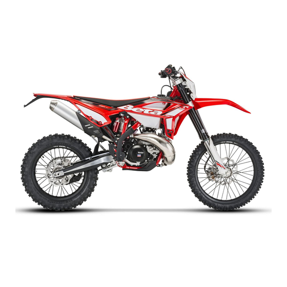
FAMILIARIZING WITH THE VEHICLE Main parts: 1 - Fuel tank 10 - Lower bumper 19 - Rear mudguard 2 - Tank cap 11 - Saddle 20 - Lateral bumper 3 - Silencer 12 - Engine 4 - Rear shock absorber 13 - Front mudguard 5 - Headlight 14 - Number-plate holder... -
Page 12: Controls
CONTROLS CLUTCH LEVER Clutch lever is fitted to the left-hand side of the handlebars. Screw can be used to alter the home position of the lever (see Adjustments). DECOMPRESSOR LEVER Decompressor lever makes the engine easier to start in case of flooding. It is also used whenever the exhaust brake needs to be reduced. - Page 13 BRAKE PEDAL Brake pedal is located in front of the right-hand footrest. The position of the pedal can be adjusted to suit the requirements of the driver (see Adjustments). DIGITAL SPEEDOMETER CYCLING THROUGH THE FUNCTIONS It is always possible to cycle through the different functions while the vehicle is sta- tionary or in motion.
- Page 14 CURRENT SPEED FUNCTION This information is constantly displayed together with an indication provided by a graphic bar. The default unit is km/h. To change the unit, press the button to access the Setup menu and select Mph. When Mph is selected, no indication is provided as to which unit is currently displayed.
- Page 15 3 - MILEOMETER FUNCTION (TOD) T≥ 3” and Vel=0 enables setting of circumference, unit and number of pulses for each wheel turn T<3” or Vel>0 cycles through functions The information is displayed together with the TOD caption. Depending on the selected unit, the information is displayed in kilometres (default) or miles and is permanently stored in non-volatile memory.
- Page 16 SLEEP MODE One minute after the last pulse from the speed sensor has been received, or after the button was last depressed, the microcontroller switches to a power-saving status named Sleep Mode. In order to save power, all standard instrument activity is sus- pended, the display and the backlighting are turned off (if the vehicle has no battery the backlighting is automatically turned off as soon as the engine is switched off) and only the clock remains in operation.
- Page 17 LH SWITCH Dip switch has three positions: = lights off = low beam on = high beam on Button operates the horn. Switch is used to stop the engine. Press the button until the engine stops. INDICATOR SWITCH Shifting lever left or right activates the left or right indicators (if installed).
-
Page 18: Specifications
SPECIFICATIONS Dry weight - RR 250 ........117 kg (front 54 Kg; rear 63 Kg) Dry weight - RR 400 - 450 ..... 117,5 kg (front 54,5 Kg; rear 63 Kg) Dry weight - RR 525 ........118 kg (front 55 Kg; rear 63 Kg) DIMENSIONS - RR 250 maximum length ................. - Page 19 CAPACITIES fuel tank ..................8,5 liter fuel type ............. petrol unleaded, with a minimum octane number of 95 (R.O.N.) including reserve ................1 liter coolant circuit ................1,3 liter motor oil type ......... synthetic oil (MOTOREX COBRA 15W40) FRONT SUSPENSION “Marzocchi”...
- Page 20 Type ........... Single cylinder, 4-stroke, liquid-cooled with countershaft and electric starting Bore x stroke RR 250 ............75 x 56,5 mm Bore x stroke RR 400 ............... 89 x 64 mm Bore x stroke RR 450 ............... 89 x 72 mm Bore x stroke RR 525 ...............
- Page 21 Fuel system ................carburettor Cooling system ..........forced liquid circulation by pump Spark plug ................. NGK DCPR 8 E Clutch .................. wet, multidisc Transmission ............ 6-speed with front claw clutch RR 250 RR 400 RR 450 RR 525 Gear ratio 1st gear...
-
Page 22: Wiring Diagrams
WIRING DIAGRAM... -
Page 23: Wiring Diagram
WIRING DIAGRAM RIGHT-HAND FRONT TURN INDICATOR (12V-10W BULB) FRONT BRAKE LIGHT BUTTON START BUTTON WHEEL REVOLUTION SENSOR HIGH BEAM WARNING LIGHT TURN INDICATOR WARNING LIGHT DISPLAY LOW BEAM WARNING LIGHT NOT CONNECTED MODE BUTTON ENGINE STOP BUTTON HORN BUTTON LIGHTS SELECTOR SWITCH TURN INDICATOR SWITCH LEFT-HAND CONTROL SET LEFT-HAND FRONT TURN INDICATOR (12V-10W BULB) -
Page 24: Electrical Devices
ELECTRICAL DEVICES BATTERY Battery is located under the saddle and requires no maintenance. It is not necessary to check the level of the electrolyte or top up with water. Keep the battery terminals clean and, if necessary, protect them with a small quan- tity of acid-free grease. - Page 25 FUSE Fuse is located in starting relay under- neath right-hand side panel . To gain access to the fuse, remove the saddle and lift tilting support , where the battery is contained. The fuse protects the following devices: •electric starter •horn •indicators •instrument panel...
- Page 27 CONTENTS...
-
Page 28: Checks To Be Performed Before Each Ride
CHECKS TO BE PERFORMED BEFORE EACH RIDE The vehicle can be used only if it is in perfect condition from a technical point of view. To ensure maximum safety, it is advisable to carry out a general inspection of the motorcycle before each ride. The checks to be performed are described below. 1 CHECK THE ENGINE OIL LEVEL Insufficient oil levels lead to early wear and, in the long run, to engine damage. -
Page 29: Recommended Lubricants
RECOMMENDED LUBRICANTS To maximize the vehicle’s performance and ensure many years of trouble-free opera- tion, we recommend using the following products: PRODUCT TYPE SPECIFICATIONS ENGINE OIL BARDAHL XTM15W 50 BRAKE OIL BARDAHL BRAKE FLUID DOT4 FORK OIL EB-H16 SAE 7,5 TIE ROD GREASE BARDAHL MPG2 CLUTCH OIL... -
Page 30: Starting The Engine
STARTING THE ENGINE COLD STARTING 1 Open fuel cock . 2 Take the vehicle off the stand. 3 Shift into neutral. 4 Operate choke . 5 WITHOUT opening the throttle, firmly and FULLY operate kickstart or use the electric starter. HOT STARTING 1 Open fuel cock . - Page 31 CHOKE When choke is pulled out completely, a hole is opened in the carburettor through which the engine can suck in extra fuel. This makes it possible to obtain a rich fuel- air mixture suitable for cold starting. To deactivate the choke, push it in to its start- ing position.
-
Page 32: Refuelling
REFUELLING FUEL TANK CAP Turn tank cap anticlockwise. Replace the tank cap and turn it clockwise. Arrange tank breather pipe so that it forms no kinks. FUEL COCK Fuel cock is closed. Before using the vehicle, turn the knob to ON. This allows the fuel to flow to the carburettor. - Page 33 CONTENTS...
- Page 34 OIL CIRCUIT Oil pump sucks engine oil from the oil sump through long oil unit . Oil pipe conveys the oil to the cylinder head up to camshaft lubrication point . The oil quan- tity is adjusted by means of oil passage screw .
- Page 35 CHANGING THE ENGINE OIL AND THE OIL FILTER Before performing this operation, if lower bumper is present, remove it after un- screwing the three screws as shown in the figure. Whenever the oil is changed, the long and short oil units need to be cleaned and both oil filters replaced.
- Page 36 CLEANING THE SHORT OIL UNIT Short oil unit is inserted in Allen screw on the lower side of the engine. Insert an Allen wrench into the screw socket and loosen the oil drain screw. Remove the oil unit, thoroughly clean its components and blow them with low-pres- sure compressed air.
- Page 37 REPLACING THE OIL FILTER Remove screw and allow the oil to drain into a container placed under the engine. Remove the four screws and take off the two oil filter covers. Using special seeger ring pliers, pull the two filter elements out of the crankcase.
- Page 38 CHECK THE LEVEL OF THE FRONT BRAKE FLUID Check the level of the brake fluid through sight . The level of the fluid should never fall below the mark in the sight. RESTORING THE LEVEL OF THE FRONT BRAKE FLUID To restore the level of the brake fluid, loosen the two screws , lift cap and add brake...
- Page 39 CHECK THE LEVEL OF THE REAR BRAKE FLUID Check the level of the brake fluid through sight . The level of the fluid should never fall below the mark in the sight. RESTORING THE LEVEL OF THE REAR BRAKE FLUID To restore the level of the brake fluid, un- screw cap and pour in brake fluid (IP...
- Page 40 FRONT BRAKE LINING CONTROL In order to verify the wear condition of front brake is enough to view the plincer from the bottom, where is possible to glimpse the brake lining tails which will have to show a brake of 2 mm in thickness. If the stratum is lesser let’s start replacing them.
- Page 41 CHECKING THE OIL LEVEL IN THE HY- DRAULIC CLUTCH To check the oil level in the clutch pump, first remove cover . Remove the two screws and take off cover together with the rubber bellows. With the clutch pump in a horizontal posi- tion, the level of the oil should be 4 mm below the upper rim.
-
Page 42: Fork Oil
FORK OIL Right/left-hand rod The procedure for changing the oil in the forks is provided only for information. We recommend having the operation per- formed by a BETAMOTOR authorized workshop. •Remove the handlebars after unscrewing the four screws fixing clevis . •Unloosen the stem clamping screws and . -
Page 43: Air Filter
AIR FILTER A dirty air filter hinders the passage of air, reduces engine power and increases fuel consumption. For these reasons it is essen- tial to clean the air filter on a regular ba- sis. Follow these steps to gain access to the air filter. -
Page 44: Spark Plug
SPARK PLUG Keeping the spark plug in good condition makes for reduced consumption and opti- mum engine performance. It is advisable to remove the spark plug when the engine is hot (and naturally off) because the carbon formation and the colour of the insulator provide important information on carburetion, lubrication, and the general condition of the engine. - Page 45 CARBURETTOR - ADJUSTING THE IDLE SPEED Engine starting is strongly affected by the idle speed adjustment. In other words, an engine whose slow running is properly adjusted is easier to start than an engine with an unsuitably tuned up engine. The idle speed is adjusted by means of adjusting wheel and mixture adjusting...
- Page 46 NOTE Failure to successfully complete the above procedure can be the result of an improp- erly sized idling jet. a) If the mixture adjusting screw is turned until it stops and no changes in the idle speed are observed, a smaller idling jet is required. b) If the engine stalls when the adjusting screw is still two turns open, a larger idling jet is needed.
- Page 47 CHECKING THE FLOAT LEVEL (float height) Remove the carburettor and the float cham- ber. Tilt the carburettor so that the float touches the float needle valve without press- ing it too hard. In this position the float edge should be parallel with the float chamber sealing sur- face (see figure).
-
Page 48: Coolant
DRAINING THE CARBURETTOR FLOAT CHAMBER The carburettor float chamber can be drained by following the procedure de- scribed below while the engine is cold. Close the fuel cock and place tube in a container to gather the fuel that flows out. Open drain screw and drain the fuel. -
Page 49: Removing The Plastics
REMOVING THE PLASTICS To facilitate checks and operations in cer- tain areas of the vehicle, it is essential to remove the bodywork sections as de- scribed below. Removing the saddle Remove the two fixing screws (one on each side), lift the saddle as shown in the figure and pull it off from the back of the vehicle. - Page 50 Removing the front side panels Unscrew the eight fixing screws (four on each side) and remove the panels. Removing the rear side panels Unscrew the four fixing screws (two on each side) and remove the panels. The upper screw fixes the saddle as well as the rear panel.
- Page 51 Removing the front mudguard Remove the four screws from underneath the front mudguard. Remove screw (also located under the mudguard) fixing the mudguard backing plate. Remove the two mudguard backing fixing screws from the top of the backing plate. Removing the fork covers Unscrew the eight fixing screws (five on the left side and three on the right side)
- Page 52 Removing the headlight fairing Release the two rubber bands as shown in the figure, pull out the headlight insert and take off fairing .
- Page 53 DRIVE CHAIN MAINTENANCE The life of the drive chain largely depends on its maintenance. Chains without X- rings must be periodically cleaned in petroleum and then immersed in hot chain oil or treated with a chain spray. X-ring chains require very little maintenance. The best way to clean them is rinsing them generously with water.
- Page 54 SUSPENSIONS TELESCOPIC FORK ADJUSTING THE REBOUND DAMPER The hydraulic rebound damper determines the behaviour of the telescopic fork during extension and can be adjusted by means of screw . Turning the screw clockwise (towards the + sign) increases the action of the rebound damper;...
- Page 55 Low-speed adjustment •Using a screwdriver, loosen screw turning it clockwise to decrease the hy- draulic compression damper. Standard adjustment: Screw completely open, 21/21 clicks High-speed adjustment •Turn knob anticlockwise to decrease the hydraulic compression damper. Standard adjustment Knob completely open, 24/24 clicks WARNING Starting from the standard position, turn the knob anticlockwise (with a closing action).
-
Page 56: Charging The Battery
CHARGING THE BATTERY Remove the battery and check its charge. Using an open-circuit multimeter (10-12 hours after the activation), check that the voltage is greater than 12.6 V. If it is lower, it is advisable to recharge the battery. Based on the type of charger available, charge the battery using either of the fol- lowing procedures: •... - Page 57 Use water jet to soften the dirt and mud accumulated on the paintwork, then remove them with a soft bodywork sponge soaked in water and shampoo (2-4 percent shampoo in water). Subsequently rinse well with water, and dry with air and cloth or suede leather.
-
Page 58: Scheduled Maintenance
SCHEDULED MAINTENANCE Interval hour (h) after/every 15 Item fuel (litre) Air filter (after off-road use) Valves Spark plug (replace every 30 hours) Idle speed Throttle cable play Clutch Engine oil Engine oil filter Motor oil net filter Exhaust pipe bolts Brakes Brake lines (replace every 4 years) Brake fluid (replace every 2 years) -
Page 59: Carburetor
PROLONGED INACTIVITY A few simple operations should be performed to keep the vehicle in good condition whenever it is to remain inactive for a long period (e.g. during the winter): • Thoroughly clean the vehicle. • Reduce the tyre pressures by approximately 30 percent, and if possible raise the tyres off the ground. - Page 61 CONTENTS...
-
Page 62: Adjusting The Decompressor Lever Control Cable
ADJUSTING THE HOME POSITION OF THE FRONT BRAKE LEVER The home position of brake lever be adjusted by means of screw . ADJUSTING THE HOME POSITION OF THE BRAKE PEDAL The home position of brake pedal be adjusted by means of set screw . Then adjust the idle travel of the pedal by means of pump control rod . -
Page 63: Adjusting The Home Position Of The Clutch Lever
ADJUSTING THE HOME POSITION OF THE CLUTCH LEVER The idle travel of clutch lever can be adjusted by means of screw . ADJUSTING THE HANDLEBARS The handlebars can be fastened in one of four positions. Lower clevis can be positioned on holes respectively and can be rotated 180 degrees to allow four different adjust- ments capable of suiting different driver’s... -
Page 64: Adjusting The Throttle Control Cable
ADJUSTING THE THROTTLE CONTROL CABLE The throttle control cable should always have a 3-5 mm play. In addition, the idle speed should not change when the han- dlebars are fully rotated to the left or right. Push back protective cap . -
Page 65: Tensioning The Chain
TENSIONING THE CHAIN To ensure the drive chain a longer life, it is advisable to periodically check its tension. Always maintain the chain clean and lu- bricated. If the chain play exceeds 20 mm, tension the chain by following these steps: 20 mm •Loosen wheel spindle nut . -
Page 66: Adjusting The Headlight
ADJUSTING THE HEADLIGHT • The light beam is adjusted manually by turning the headlight fixing screws on the headlight fairing. • Periodically check the direction of the beam. The beam can only be adjusted vertically. • Place the vehicle on level ground (but not on the stand) 10 metres from a vertical wall. - Page 67 CONTENTS...
- Page 68 REPLACING THE BRAKE PADS The procedure for replacing the brake pads is provided only for information. We rec- ommend having the operation performed by a BETAMOTOR authorized workshop. FRONT Follow these steps to replace the pads: •Push the brake caliper towards the disc so that the pistons reach their home posi- tions.
- Page 69 REAR Follow these steps to replace the pads: •Push the brake caliper towards the disc so that the pistons reach their home posi- tions. •Unscrew dowel •Pull out pin while supporting the two pads as shown in the figure. •Remove the brake pads taking care not to drop the leaf spring located above the two pads.
-
Page 70: Replacing The Headlight Bulbs
REPLACING THE HEADLIGHT BULBS Release both elastic bands and move the headlight fairing forwards. Carefully pull out the parking light bulb together with bulb holder from the head- light reflector. Detach connector from the headlight bulb and remove rubber cap . Turn fixing flange anticlockwise and re- move the bulb from the headlight reflector. -
Page 71: Replacing The Exhaust-Pipe
REPLACING THE EXHAUST-PIPE The description of the exhaust-pipe substi- tution is purely informative; actually is ad- visable to turn to a BETAMOTOR shop in order to make this. As for substitution you must proceed in the following way: •Put the motor-cycle on the stand under the motor •Remove the saddle (vedi pag. - Page 72 •Unthread the loom toward the back •Remove the upper fixing bolt of the damper in order to make it possible for the exhaust-pipe to pass •Remove the two springs attacked to the cylinder . •Unscrew the bolt over the lever set in motion and remove the tube running it from the back.
- Page 73 CONTENTS...
- Page 74 PROBLEM CAUSE REMEDY - Fuel system clogged (fuel lines, Clean the system. Engine does not start fuel tank, fuel cock). - Air filter dirty. Proceed as described on page 119. - No current supplied to spark Clean or replace the spark plug. plug.
-
Page 75: Suspensions: Telescopic Fork And Shock Absorber
Adjusting decompressor ..............138 Air filter .................... 119 Bleeding clutch .................. 117 Bleeding the brakes: front and rear ............114 Brakes, adjustment: front and rear ............138 Carburetor ..................121 Checks to be performed before each ride ..........104 Clutch, adjustment ................139 Clutch oil: check the level .............. - Page 76 ..........................................................................................................................................................................................................................................................................................................................................................................................................................................................................................................................................................................................................................................................................................................................................
Need help?
Do you have a question about the RR 250 and is the answer not in the manual?
Questions and answers