Sign In
Upload
Manuals
Brands
Toro Manuals
Lawn Mower
Reelmaster 5510 Series
Toro Reelmaster 5510 Series Manuals
Manuals and User Guides for Toro Reelmaster 5510 Series. We have
3
Toro Reelmaster 5510 Series manuals available for free PDF download: Service Manual, Operator's Manual
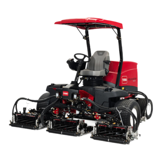
Toro Reelmaster 5510 Series Service Manual (662 pages)
Models with InfoCenter Display
Brand:
Toro
| Category:
Lawn Mower
| Size: 61 MB
Table of Contents
Table of Contents
8
Chapter 1: Safety
11
Safety Instructions
12
Jacking Instructions
16
Safety and Instructional Decals
17
Chapter 2: Specifications and Maintenance
19
Specifications
20
Torque Specifications
23
Shop Supplies
28
Special Tools
30
Chapter 3: Kubota Diesel Engine
37
Specifications
37
General Information
39
Adjustments
40
Service and Repairs
42
Chapter 4: Yanmar Diesel Engine
63
Specifications
63
General Information
66
Service and Repairs
72
Table of Contents
93
Specifications
94
Kubota Gasoline Engine
94
Chapter 5: Kubota Gasoline Engine
95
Specifications
95
General Information
96
Traction Unit Operator's Manual
96
Kubota Workshop and Diagnosis Manuals
96
Kubota Gasoline Engine
96
Engine Electronic Control Unit (ECU)
96
Service and Repairs
98
Air Cleaner Assembly
99
Exhaust System
101
Fuel System
103
Fuel Evaporative Control System
106
Radiator and Oil Cooler Assembly
109
Engine
113
Table of Contents
119
Specifications
122
Hydraulic System
122
Chapter 6: Hydraulic System
123
Specifications
123
General Information
124
Checking the Hydraulic Fluid
124
Pushing or Towing the Traction Unit
125
Releasing Pressure from the Hydraulic System
126
Traction Circuit Component Failure
127
Hydraulic Hoses
128
Installing the Hydraulic Hose and Tube (O-Ring Face Seal Fitting)
129
Installing the Hydraulic Fittings (SAE Straight Thread O-Ring Fitting into the Component Port)
131
Hydraulic Schematics
135
Hydraulic Flow Diagrams (5410/5410-D/5510/5510-D/5610)
138
Traction Circuit (5410/5410-D/5510/5510-D/5610)
138
Mow Circuit (5410/5410-D/5510/5510-D/5610)
141
Lift Circuit (5410/5410-D/5510/5510-D/5610)
144
Steering Circuit (5410/5410-D/5510/5510-D/5610)
148
Hydraulic Flow Diagrams (5610-D)
150
Traction Circuit (5610-D)
150
Mow Circuit (5610-D)
153
Lift Circuit (5610-D)
156
Steering Circuit (5610-D)
160
Special Tools
162
Hydraulic Pressure Testing Kit
162
GPM Hydraulic Tester Kit (Pressure and Flow)
162
GPM Hydraulic Tester (Pressure and Flow)
163
Hydraulic Hose Kit
163
O-Ring Kit
163
Hydraulic Test Fitting Kit
164
High Flow Hydraulic Filter Kit
165
Spindle Plug
165
Wheel Hub Puller
165
Measuring Container
166
Remote Starter Switch
167
Troubleshooting
168
Testing the Hydraulic System
174
Traction Circuit Relief Valve (R3) and (R4) Pressure Test (5410/5410-G/5410-D/5510/5510-G/5510-D/5610)
177
Traction Circuit Charge Pressure Test (5410/5410-G/5410-D/5510/5510-G/5510-D/5610)
180
Gear Pump (P3) Flow Test (Using Tester with Flow Meter and Pressure Gauge) (5410/5410-G/5410-D/5510/5510-G/5510-D/5610)
183
Front Wheel Motor Efficiency Test (5410/5410-G/5410-D/5510/5510-G/5510-D/5610)
186
Piston (Traction) Pump Flow Test (Using Tester with Flow Meter and Pressure Gauge) (5410/5410-G/5410-D/5510/5510-G/5510-D/5610)
189
Relief Valve (R1) and (R2) Pressure Test (Cutting (Mow) Circuit) (5410/5410-G/5410-D/5510/5510-G/5510-D/5610)
192
Gear Pump (P1) and (P2) Flow Test (Using Tester with Flow Meter and Pressure Gauge) (5410/5410-G/5410-D/5510/5510-G/5510-D/5610)
195
Cutting Reel Motor Efficiency Test (Using Tester with Flow Meter and Pressure Gauge) (5410/5410-G/5410-D/5510/5510-G/5510-D/5610)
198
Cutting Reel Motor Cross-Over Relief Pressure Test (5510/5510-G/5510-D/5610)
201
Lift Relief Valve (SVRV) Pressure Test (5410/5410-G/5410-D/5510/5510-G/5510-D/5610)
204
Gear Pump (P4) Flow Test (Using Tester with Flow Meter and Pressure Gauge) (5410/5410-G/5410-D/5510/5510-G/5510-D/5610)
207
Lift Cylinder Internal Leakage Test (5410/5410-G/5410-D/5510/5510-G/5510-D/5610)
210
Steering Relief Valve (R10) Pressure Test (5410/5410-G/5410-D/5510/5510-G/5510-D/5610)
214
Steering Cylinder Internal Leakage Test (5410/5410-G/5410-D/5510/5510-G/5510-D/5610)
217
Testing the Traction Circuit-Charge Pressure (5610-D)
219
Testing the Traction Circuit-Wheel Motor Efficiency (5610-D)
222
Testing the Traction Circuit-Piston Pump/Hydrostat Flow and Relief Pressure (5610-D)
228
Testing the Mow Circuit-Circuit Pressure (5610-D)
231
Testing the Mow Circuit-Reel Motor Efficiency/Case Drain (5610-D)
234
Testing the Mow Circuit-Reel Motor Cross−Over Relief Pressure (5610-D)
238
Testing the Mow Circuit-Relief Valve (RV1) and (RV2) Pressure (5610-D)
241
Testing the Mow Circuit-Gear Pump (P1) and (P2) Flow (5610-D)
245
Testing the Steering Circuit-Steering Control Valve, Relief Valve (R10) Pressure, and Steering Cylinder (5610-D)
248
Testing the Steering Circuit-Gear Pump (P3) Flow (5610-D)
251
Testing the Lift Circuit-Relief Valve (SVRV) Pressure (5610-D)
254
Testing the Lift Circuit-Lift Cylinder Internal Leakage (5610-D)
257
Testing the Lift Circuit-Gear Pump (P4) Flow (5610-D)
260
Service and Repairs
263
General Precautions for Removing and Installing the Hydraulic System Components
263
Checking the Hydraulic Lines and Hoses
264
Priming the Hydraulic Pumps
264
Flushing the Hydraulic System
265
Filtering the Closed-Loop Traction Circuit
267
Charging the Hydraulic System
269
Hydraulic Tank
272
Piston (Traction) Pump Control Assembly
274
Hydraulic Pump Driveshaft
277
Hydraulic Pump Assembly
281
Servicing the Piston (Traction) Pump
286
Servicing the Gear Pump
288
Front Wheel Motors
292
Servicing the Front Wheel Motor
295
Rear Wheel Motors (Machine with Crosstrax AWD)
297
Servicing the Rear Wheel Motor (Machine with Crosstrax AWD)
301
Crosstrax™ AWD Control Manifold Assembly
303
Servicing the Crosstrax AWD Control Manifold Assembly
305
Mow Control Manifold Assembly
306
Servicing the Mow Control Manifold Assembly
309
Lift Control Manifold
313
Servicing the Lift Control Manifold
316
Servicing a Control Manifold Cartridge Valve
318
Cutting Reel Motor
320
Servicing the Cutting Reel Motor (Casappa)
323
Servicing the Cutting Reel Motor (Sauer-Danfoss)
329
Lift Cylinder
334
Servicing the Lift Cylinder
337
Steering Control Valve
340
Servicing the Steering Control Valve
344
Steering Cylinder
345
Servicing the Steering Cylinder
348
Oil Cooler (5410/5510/5610)
351
Chapter 7: Electrical System
357
General Information
359
Electrical Schematic and Wire Harness Drawings/Diagrams
359
Toro Electronic Controller (TEC)
359
CAN-Bus Communications
359
Yanmar Engine Electronic Control Unit (ECU)
360
Yanmar Engine Electrical Components
361
Kubota Gasoline Engine Electronic Control Unit (ECU)
361
Kubota Gasoline Engine Electrical Components
361
Special Tools
363
Multimeter
363
Terminal Protector
363
Battery Hydrometer
363
Dielectric Gel
364
Infocenter Display
365
Splash Screen
367
Main Information Screen
368
Operator Advisory Screen
369
Main Menu Screen
370
Faults Screen
372
Service Screen
374
Diagnostics Screen
375
Settings Screen
377
About Screen
381
Troubleshooting
382
Operator Advisories
382
Using the Infocenter Display for Troubleshooting
384
Machine Faults
388
Engine Faults
391
General Run and Transport Problems
395
Electrical System Quick Checks
400
Testing the Battery (Open Circuit Test)
400
Testing the Charging System
400
Testing the Glow Plug System (Machines with Kubota Diesel Engine)
401
Checking the Operation of the Interlock Switches
401
Adjustments
402
Traction Neutral Switch
402
Parking Brake Switch
404
Cutting Unit down Limit Switch
406
Mow/Transport Switch
408
Testing the Electrical Components
410
Fusible Link Harness (Machines with Kubota or Yanmar Diesel Engine)
410
System Fuses
412
Engine Fuses (Gasoline Engine)
412
Toro Electronic Controller (TEC)
417
Key Switch
420
Reel Engage Switch
422
Engine Speed Switch (if Equipped)
424
Lower/Raise Joystick Switches
426
Headlight Switch
428
Seat Switch
430
Cutting Unit down Limit Switch
432
Traction Neutral Switch
434
Parking Brake Switch
436
Mow/Transport Switch
438
Backlap Switches
440
Oil Pressure Switch (Machine with Kubota Engine)
442
Relays with 4 Terminals
444
Relays with 5 Terminals (Diesel Engine)
446
Engine Relays with 5 Terminals (Gasoline Engine)
448
Hydraulic Solenoid Valve Coils
451
Temperature Sender (Machine with Kubota Diesel Engine)
454
Engine Run Solenoid (Machine with Kubota Diesel Engine)
456
Fuel Sender (Diesel Engine)
458
Fuel Sender (Gasoline Engine)
461
Fuel Pump (Machine with Yanmar Diesel Engine)
464
Fuel Pump (Machine with Kubota Diesel Engine)
466
Fuel Pump (Machine with Kubota Gasoline Engine)
468
CAN-Bus Terminator Resistor
470
Resistor Assembly (Machine with Yanmar Diesel or Kubota Gasoline Engine)
472
Diode Assemblies (Diesel Engine)
474
Hydraulic Solenoid Valve Coils
476
Service and Repairs
476
Backlap Switches
478
Battery Care
480
Battery Storage
480
Servicing the Battery
481
Table of Contents
489
Chapter 8 :Chassis
490
Specifications
490
Chassis
490
General Information
491
Special Tools
492
Wheel Hub Puller
492
Service and Repairs
493
Wheels
493
Steering Column
495
Servicing the Brakes
498
Rear Wheel Bearings (Machines with 2-Wheel Drive)
502
Rear Axle Motor Housings
504
Rear Axle
507
Control Arm
511
Operator Seat
514
Mechanical Seat Suspension
518
Front Lift Arms
521
Rear Lift Arms
525
Hood
529
Table of Contents
531
Specifications
532
Cutting Unit Specifications
532
Chapter 9: Cutting Unit
533
Specifications
533
General Information
534
Special Tools
535
Aftercut Appearance
540
Adjustments
543
Characteristics
543
Adjusting the Reel Bearing (Cutting Units with Painted Side Plates)
543
Leveling the Rear Roller
545
Service and Repairs
547
Hydraulic Reel Motor
547
Backlapping
549
Bedbar Assembly
550
Bedknife Replacement and Grinding
553
Servicing the Bedbar Adjuster
557
Reel Assembly (Cutting Units with Painted Side Plates)
559
Reel Assembly Service (Cutting Units with Painted Side Plates)
563
Reel Assembly (Cutting Units with Aluminum Side Plates)
565
Reel Assembly Service (Cutting Units with Aluminum Side Plates)
569
Preparing the Reel for Grinding
572
Front Roller
573
Rear Roller
575
Servicing the Roller
577
Rear Roller Brush - Optional (Cutting Units with Painted Side Plates)
581
Rear Roller Brush - Optional (Cutting Units with Aluminum Side Plates)
587
Chapter 10: Belt Driven Groomer (Optional)
595
General Information
596
Grooming Performance
596
Groomer Reel Mechanical Problems
597
Adjustments
598
Adjusting the Height/Depth of the Groomer
598
Service and Repairs
600
Replacing the Groomer Drive Belt
601
Groomer Plate Assembly
603
Groomer Reel
609
Servicing the Groomer Reel
612
Groomer Pivot Hub
614
Height Adjuster Assembly
617
Servicing the Grooming Brush (Optional)
618
Chapter 11: Universal Groomer (Optional)
621
General Information
622
Factors Affecting Grooming
622
Troubleshooting
623
Groomer Reel Mechanical Problems
623
Service and Repairs
624
Gear Box Assembly
626
Idler Assembly
631
Groomer Reel
633
Servicing the Groomer Reel
635
Height Adjuster Assembly
637
Servicing the Grooming Brush (Optional)
639
Appendix A
641
Electrical Drawing Designations
642
Hydraulic Schematic-5410/5410-D
643
Hydraulic Schematic-5510/5510-D/5610
644
Hydraulic Schematic-5610-D
645
Electrical Schematic-5410/5510/5610 (Models with Kubota Diesel Engine)
646
Electrical Schematic-5410-D/5510-D (Models with Yanmar Diesel Engine)
647
Electrical Schematic-5610-D
648
Electrical Schematic-5410-G/5510-G (Models with Kubota Gasoline Engine)
649
Wire Harness Drawing-Main
650
Wire Harness Drawing-Seat
652
Engine Wire Harness Drawing-5410/5510/5610 (Models with Kubota Diesel Engine)
654
Engine Wire Harness Diagram-5410/5510/5610 (Models with Kubota Diesel Engine)
655
Engine Wire Harness Drawing-5410-D/5510-D (Models 03672 and 03687 with Yanmar Diesel Engine)
656
Engine Wire Harness Diagram-5410-D/5510-D (Models 03672 and 03687 with Yanmar Diesel Engine)
657
Engine Wire Harness Drawing-5410-D/5510-D/5610-D (Models 03606 03607, and 03679)
658
Engine Wire Harness Diagram-5410-D/5510-D/5610-D (Models 03606 03607, and 03679)
659
Engine Wire Harness Drawing-5410-G/5510-G (Models with Kubota Gasoline Engine)
660
Engine Wire Harness Diagram-5410-G/5510-G (Models with Kubota Gasoline Engine)
661
Advertisement
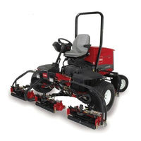
Toro Reelmaster 5510 Series Operator's Manual (24 pages)
8 or 11-Blade DPA Cutting Unit with 7in Reel
Brand:
Toro
| Category:
Lawn and Garden Equipment
| Size: 1.33 MB
Table of Contents
Table of Contents
3
Safety
3
Safety and Instructional Decals
4
Setup
5
Inspecting the Cutting Unit
5
Using the Cutting Unit Kickstand
5
Adjusting the Rear Shield
6
Mounting the Counter Weights
6
Product Overview
7
Specifications
7
Cutting Unit Accessories and Kits
7
Operation
8
Adjustments
8
Turf Compensation Settings
11
Height-Of-Cut
11
Servicing the Bedknife
16
Maintenance
18
Lubricating the Cutting Unit
18
Adjusting the Reel Bearings
18
Servicing the Bedbar
19
Servicing the HD Dual Point Adjusters (DPA)
20
Servicing the Roller
21
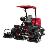
Toro Reelmaster 5510 Series Operator's Manual (20 pages)
8 and 11 blade dpa cutting units with 7 inch reels
Brand:
Toro
| Category:
Lawn Mower
| Size: 0.83 MB
Table of Contents
Table of Contents
2
Introduction
2
Safety
3
Safety and Instructional Decals
3
Setup
4
Inspection
4
Cutting Unit Kickstand
4
Figure
4
Adjusting the Rear Shield
5
Mount the Counter Weights
5
Product Overview
7
Specifications
7
Cutting Unit Accessories and Kits (See Parts Catalog for Part Numbers)
8
Operation
9
Adjustments
9
Height of Cut Chart Terms
10
Height of Cut Chart
11
Adjusting the Height of Cut
12
Servicing Bedknife
13
Maintenance
15
Lubrication
15
Adjusting the Reel Bearings
15
Servicing the Bedbar
16
Servicing the Roller
17
Advertisement
Advertisement
Related Products
Toro REELMASTER 3500-D
Toro Reelmaster 2000
Toro reelmaster 3550 series
Toro reelmaster 5210 series
Toro reelmaster 5410 series
Toro Reelmaster 5610 Series
Toro Reelmaster Edge Series
Toro Reelmaster ReelEdge Series
Toro REELMASTER 4500-D
Toro Recycler II ProLine 21
Toro Categories
Lawn Mower
Lawn Mower Accessories
Snow Blower
Lawn and Garden Equipment
Utility Vehicle
More Toro Manuals
Login
Sign In
OR
Sign in with Facebook
Sign in with Google
Upload manual
Upload from disk
Upload from URL